
Introduction
With the rapid development of industrial automation, variable frequency drives (VFDs) have evolved from simple motor speed regulators into intelligent drive systems integrating motor control, speed feedback, torque management, communication functions, and advanced fault diagnosis.
In applications requiring high speed accuracy and dynamic response, such as machine tools, cranes, textile equipment, printing machinery, packaging lines, and automated production systems, closed-loop vector control with encoder feedback has become increasingly common.
The AnyHz (Foster Technology) FST-650 series is a high-performance vector control inverter that supports multiple control modes, including:
- V/F control;
- Sensorless vector control;
- Closed-loop vector control with encoder feedback.
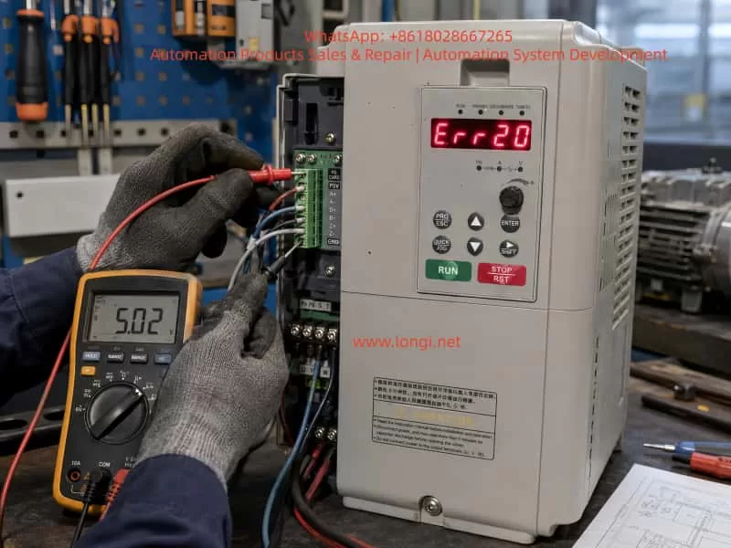
When the FST-650 displays the fault code Err20, the inverter has detected an abnormality in the encoder feedback system.
The meaning of Err20 is:
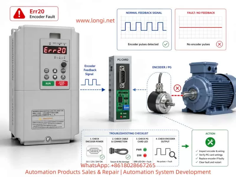
Err20 = Encoder Fault / PG Card Fault
However, in practical maintenance work, Err20 does not always mean that the encoder itself is damaged. Many real-world cases are caused by:
- Incorrect control mode selection;
- Wrong encoder parameter settings;
- Encoder wiring problems;
- Missing encoder power supply;
- PG card failure;
- Incorrect replacement configuration.
This article provides a detailed analysis of the working principle behind Err20, common causes, diagnostic procedures, and repair methods to help engineers quickly troubleshoot AnyHz FST-650 encoder-related faults.
1. Working Principle of Err20 Fault in FST-650 Inverter
1.1 The Role of Encoder Feedback in Closed-Loop Vector Control
A conventional inverter operating in open-loop mode controls the motor based on the output frequency and voltage.
For example:
- Frequency command: 50Hz;
- Output voltage calculated according to motor model;
- Motor speed estimated by inverter algorithm.
This type of control does not require an encoder.
However, in closed-loop vector control, the inverter must continuously know:
- Actual motor speed;
- Rotor position;
- Rotation direction;
- Speed deviation.
Therefore, an encoder is installed on the motor shaft.
The control process is:
Speed Command
      ↓
Vector Control Algorithm
      ↓
IGBT Output Three-Phase Power
      ↓
Motor Rotation
      ↓
Encoder Detects Actual Speed
      ↓
PG Card Processes Feedback Signal
      ↓
CPU Receives Feedback Data
      ↓
Adjusts Output Frequency and Torque
The encoder acts like the “eyes” of the inverter.
If the encoder signal disappears, the inverter cannot accurately determine the motor operating condition, so it triggers Err20 protection.
2. Main Causes of AnyHz FST-650 Err20 Fault
According to the FST-650 technical documentation, Err20 is mainly related to encoder feedback abnormalities. The possible causes include:
- Incorrect encoder type setting;
- Incorrect encoder wiring;
- Damaged encoder;
- Faulty PG feedback card.
In practical applications, these causes can be divided into several categories.
2.1 Incorrect Encoder Type Setting
This is one of the most common reasons for Err20.
The FST-650 supports different feedback devices, such as:
- Incremental AB encoder;
- ABZ encoder;
- UVW encoder;
- Resolver.
Different encoder types output completely different signals.
For example:
Actual hardware:
Incremental encoder
A+
A-
B+
B-
But inverter parameter setting:
UVW encoder
The encoder itself may be working normally, but the inverter receives an incompatible signal format.
The result:
Encoder signal abnormal
        ↓
No valid speed feedback
        ↓
Err20 alarm
2.2 Encoder Wiring Failure
Encoder systems usually contain several signal lines:
| Signal | Function |
|---|---|
| +5V | Encoder power supply |
| GND | Power ground |
| A+ | Channel A positive signal |
| A- | Channel A negative signal |
| B+ | Channel B positive signal |
| B- | Channel B negative signal |
| Z+ | Zero pulse signal |
| Z- | Zero pulse return signal |
Any problem in these connections may cause Err20.
Common wiring problems include:
- Broken encoder cable;
- Loose connector;
- Poor grounding;
- Incorrect phase connection;
- Damaged shielding layer.
For example:
If the encoder power supply line is disconnected:
Encoder has no power
        ↓
No pulse output
        ↓
PG card receives no signal
        ↓
Err20
2.3 Encoder Damage
Encoders are precision electronic components. Long-term operation may cause:
- Optical sensor aging;
- Internal IC failure;
- Mechanical shaft damage;
- Dust or moisture contamination;
- Vibration damage.
Typical symptom:
The inverter powers on normally.
However:
When the motor starts running:
Motor rotates
       ↓
Encoder should output pulses
       ↓
No feedback detected
       ↓
Err20 appears
At standstill, the problem may not be obvious because the encoder is not generating speed pulses.
2.4 PG Card Failure
The PG card is the interface between the encoder and inverter CPU.
Its function:
Encoder signal
       ↓
Signal conditioning
       ↓
Voltage conversion
       ↓
Filtering
       ↓
CPU feedback input
If the PG card fails, even a good encoder cannot provide feedback to the inverter.
Typical PG card failures:
- Input circuit damage;
- RS422 receiver failure;
- Optical isolation failure;
- Power supply abnormality;
- Poor connector contact.
3. First Maintenance Step: Confirm Whether an Encoder Is Actually Required
A very common situation in the field is:
The inverter reports Err20, but the motor does not have an encoder.
This usually happens after:
- Parameter reset;
- Replacement of inverter;
- Second-hand equipment installation;
- Incorrect commissioning.
Example:
Original system:
Standard motor
+
V/F control
After parameter modification:
Closed-loop vector control enabled
The inverter starts searching for encoder feedback:
No encoder signal
        ↓
Err20
Check Control Mode Parameter
Enter the inverter parameter menu and check the control mode.
If the inverter is set to:
Closed-loop vector control
then the system must have:
- Encoder;
- PG card;
- Correct encoder parameters.
If the machine does not use an encoder, change the control mode to:
V/F Control
or:
Sensorless Vector Control
Then save the parameters and restart the inverter.
4. Complete Err20 Troubleshooting Procedure
The following procedure is suitable for field maintenance.
Step 1: Determine When Err20 Appears
Situation A: Err20 appears immediately after power-on
Possible causes:
- Wrong parameters;
- PG card failure;
- Encoder configuration mismatch.
Focus on:
- Control mode;
- Encoder type;
- PG card installation.
Situation B: Err20 appears only after motor starts
Possible causes:
- Encoder signal loss;
- Encoder cable problem;
- Encoder damage.
Focus on:
- Encoder output waveform;
- Cable continuity;
- Mechanical installation.
Step 2: Check Whether a PG Card Exists
Open the inverter control section.
Confirm whether a PG expansion card is installed.
If:
- Control mode = closed-loop vector;
- No PG card installed;
then Err20 is expected.
The solution is:
Change the control mode.
Step 3: Check Encoder Power Supply
Use a multimeter.
Measure:
Encoder +5V – GND
Normal value:
Approximately:
5V DC
If voltage is:
- 0V;
- unstable;
- significantly lower;
check:
- PG card power supply;
- Cable short circuit;
- Encoder internal failure.
Step 4: Check Encoder Output Signal
For incremental encoders:
Rotate the motor shaft manually.
The A and B channels should generate pulse changes.
Normal signal:
A channel:

0V → 5V → 0V → 5V

B channel:

Phase shifted 90° from A channel
If there is no signal:
Possible causes:
- Encoder failure;
- Missing power supply;
- Broken cable.
Step 5: Verify Encoder Parameters
Important parameters include:
Encoder Type
The inverter setting must match the actual encoder.
Example:
Actual:
AB incremental encoder
Parameter:
AB encoder
Incorrect:
Resolver
or:
UVW encoder
Encoder Resolution
Example:
Encoder nameplate:
1024 P/R
Parameter must be:
1024
Incorrect pulse number settings may cause:
- Incorrect speed feedback;
- Speed deviation;
- Err20 alarm.
5. Typical Field Repair Case
Fault Description
A machine equipped with AnyHz FST-650 inverter shows:
Err20
The motor cannot start.
Inspection Results
- Motor has no encoder;
- No PG card installed;
- Inverter configured for closed-loop vector control.
Fault Analysis
The inverter entered closed-loop vector mode.
The CPU expected encoder feedback.
However:
No encoder signal existed.
Therefore:
Missing feedback
        ↓
Encoder fault detection
        ↓
Err20
Solution
Change control mode:
Closed-loop vector control
              ↓
Sensorless vector control
Save parameters.
Power cycle inverter.
Result:
Machine returns to normal operation.
6. Precautions When Replacing an Encoder
Replacing an encoder is not simply a matter of installing a new component.
Several factors must be considered.
6.1 Mechanical Installation
The encoder shaft must be:
- Properly aligned;
- Concentric with the motor shaft;
- Mechanically fixed.
Poor installation may cause:
- Vibration;
- Pulse loss;
- Feedback instability.
6.2 Rotation Direction Verification
If A/B phase sequence is reversed:
Symptoms:
- Motor rotates opposite direction;
- Speed feedback abnormal.
Solutions:
- Exchange A and B signals;
- Modify encoder direction parameter.
6.3 Encoder Resolution Matching
The replacement encoder must have the same resolution.
Example:
Original:
2048 P/R
Replacement:
1024 P/R
may cause:
- Incorrect speed calculation;
- Speed deviation;
- Control instability.
7. Difference Between Err20 and Other FST-650 Faults
Correct fault identification prevents unnecessary replacement.
Err19
Motor auto-tuning fault.
Common causes:
- Incorrect motor parameters;
- Auto-tuning failure.
Err20
Encoder feedback fault.
Focus on:
- Encoder;
- PG card;
- Feedback wiring;
- Encoder parameters.
Err21
EEPROM read/write fault.
Usually related to:
- Control board memory;
- Parameter storage failure.
8. Recommended Repair Strategy
For AnyHz FST-650 Err20 faults, follow this sequence:
1. Confirm control mode
Does the application actually require an encoder?
2. Check PG card
Verify:
- Installed or not;
- Connector condition;
- Power supply.
3. Check encoder power
Confirm:
+5V supply is stable
4. Check encoder output
Verify:
- A/B pulse signals;
- Signal quality;
- Cable condition.
5. Verify parameters
Confirm:
- Encoder type;
- Pulse number;
- Motor parameters.
Conclusion
The AnyHz FST-650 Err20 fault is essentially a protection response caused by abnormal speed feedback in the closed-loop vector control system.
Although the display message indicates an “encoder fault”, the actual cause may exist in multiple areas:
- Incorrect control mode;
- Wrong encoder configuration;
- Wiring problems;
- Encoder power failure;
- PG card damage;
- Encoder hardware failure.
In practical maintenance work, engineers should avoid immediately replacing the encoder. A systematic troubleshooting approach is more effective:
Control Mode Verification → PG Card Inspection → Encoder Power Check → Signal Measurement → Parameter Verification → Hardware Replacement
Understanding the operating principle of closed-loop vector control allows technicians to diagnose FST-650 Err20 faults faster, reduce unnecessary component replacement, and improve industrial equipment maintenance efficiency.