
1. Application Background
In dust extraction fan retrofit projects, the variable frequency drive often needs to accept remote PLC control while retaining a local operating option for commissioning, maintenance, and emergency adjustment.
A typical requirement is as follows:
Remote mode: the PLC sends a 4–20mA analog signal to control fan speed.
Local mode: the operator sets the frequency directly from the VFD keypad.
LI1 is used as the run/stop command input.
LI3 is used to switch between local and remote frequency reference sources.
AO1 provides actual output frequency feedback to the PLC.
AO2 provides actual output current feedback to the PLC.
This control architecture is commonly used for dust extraction fans, exhaust fans, induced draft fans, supply fans, ventilation fans, circulation fans, and other centrifugal fan applications.
Although the wiring appears straightforward, commissioning problems are often caused by inconsistent parameter planning rather than incorrect wiring. Typical issues include selecting the wrong analog input channel, setting the wrong current range, confusing run-command switching with frequency-reference switching, or assigning unsuitable analog output scaling.
The Controlway IE series VFD provides two frequency reference channels, configurable digital inputs, AI1 and AI2 analog inputs, as well as AO1 and AO2 analog outputs. These functions make it suitable for PLC-controlled fan systems requiring both local and remote operation.

2. Define the Control Architecture Before Editing Parameters
Before changing any VFD parameters, the complete control structure should be defined clearly.
For this application, the recommended arrangement is:
Run command source: external terminals.
Run/stop input: LI1.
Remote frequency reference: AI2, 4–20mA signal from PLC.
Local frequency reference: VFD keypad frequency setting.
Frequency reference selection input: LI3.
AO1 output: actual output frequency, 4–20mA.
AO2 output: actual output current, 4–20mA.
The operating logic should be as follows:
In remote mode, the PLC sends a 4–20mA signal to AI2. The VFD converts this analog signal into the target operating frequency.
In local mode, the VFD ignores the remote frequency reference and follows the frequency manually entered through the keypad.
LI1 remains responsible for start and stop control in both local and remote frequency modes.
A critical distinction must be made between run-command source switching and frequency-reference source switching.
Run-command source switching determines whether the VFD start/stop command comes from the keypad, external terminals, or communication.
Frequency-reference source switching determines whether the speed command comes from AI2, AI1, keypad setting, communication, multi-speed inputs, or another source.
In many dust extraction fan projects, only the frequency reference needs to change between local and remote modes. The run/stop command remains controlled through LI1 or the PLC. In that case, the VFD must remain in external terminal run-command mode. Only the frequency source should switch between AI2 and keypad reference.
If the VFD is switched completely to keypad local mode, LI1 start/stop control may no longer function as intended. This is a frequent cause of commissioning confusion.
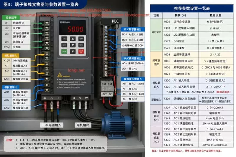
3. Run Command Configuration
The Controlway IE series normally uses parameter f002 to select the run command channel.
Typical selections are:
f002 = 0: External terminal run command.
f002 = 1: Keypad run command.
f002 = 2: Serial communication run command.
For this application, the recommended setting is:
f002 = 0
This ensures that the fan is always started and stopped through external terminal logic.
LI1 should be configured as a forward run command.
When LI1 is active, the VFD runs the fan.
When LI1 is inactive, the VFD stops the fan.
For a standard one-direction dust extraction fan, LI1 is normally assigned to forward run only. Reverse operation is generally unnecessary and may create process problems, reverse airflow, belt stress, abnormal duct pressure, or unexpected dust movement.
A recommended arrangement is:
LI1: Forward run command.
LI2: Unused, fault reset, or reserved.
Reverse operation: Disabled.
The stop mode should also be selected according to the fan inertia and process requirements. For most dust extraction fans, deceleration stop is preferred because it provides a controlled stop. Free-run stop may cause a large fan to coast for a long period, affecting process interlocks and safety sequencing.
4. AI2 as the PLC 4–20mA Remote Frequency Reference
In remote mode, the PLC analog output should be wired to AI2.
The standard scaling principle is:
4mA = minimum frequency.
20mA = maximum frequency.
Intermediate current values correspond proportionally to intermediate frequencies.
For example, if the fan maximum frequency is 50Hz:
4mA = 0Hz or the minimum allowed operating frequency.
12mA = 25Hz.
20mA = 50Hz.
In many fan applications, the lower limit should not be set to 0Hz. Fans may suffer from poor cooling, unstable airflow, resonance, or insufficient dust extraction at very low speed.
For example:
4mA = 20Hz.
20mA = 50Hz.
Under this configuration, the fan runs at 20Hz when the PLC output is 4mA and reaches 50Hz at 20mA.
The minimum frequency should be determined according to fan curve, motor cooling, duct resistance, process airflow demand, and mechanical vibration conditions.
The Controlway IE series allows separate main and auxiliary frequency references. The recommended configuration is:
f003 = AI2.
f005 = Keypad frequency setting.
f006 = Frequency reference switching mode between f003 and f005.
f021 = Single-channel frequency reference structure.
With this arrangement:
Main frequency reference: AI2, used for remote PLC control.
Auxiliary frequency reference: keypad setting, used for local manual adjustment.
LI3 is then used to switch between the two frequency reference sources.
5. LI3 as the Local/Remote Frequency Reference Selector
LI3 should be assigned to the frequency-reference switching function.
It should not be assigned as a normal run command, stop command, multi-speed input, reset input, or other unrelated function.
A typical operating definition can be:
LI3 OFF: Remote mode, frequency reference from AI2.
LI3 ON: Local mode, frequency reference from keypad.
The opposite logic can also be used:
LI3 ON: Remote mode.
LI3 OFF: Local mode.
Either method is acceptable, but the electrical design, PLC program, switch label, operation manual, and VFD parameter logic must all match exactly.
A common site problem occurs when the selector switch is labeled “REMOTE,” but the actual LI3 state causes the VFD to use keypad frequency. Operators then assume that the PLC system has failed even though the VFD is simply using the wrong reference source.
The panel door should clearly identify the operating condition, for example:
REMOTE: PLC AI2 4–20mA frequency reference.
LOCAL: VFD keypad frequency reference.
RUN/STOP: Controlled by LI1.
The logic input type must also match the PLC output type.
The Controlway IE series supports source logic and sink logic.
For PNP transistor outputs, source logic is normally used.
For NPN transistor outputs, sink logic is normally used.
For relay dry-contact outputs, the actual control supply connection and COM/0V wiring must be checked carefully.
An incorrect source/sink logic setting can cause LI1 or LI3 to operate in reverse, remain permanently active, or fail to respond.
6. AI2 4–20mA Wiring and Signal Considerations
The PLC analog output should generally be connected as follows:
PLC AO+ to VFD AI2.
PLC AO− to VFD analog common or signal COM.
Use shielded twisted-pair cable for the analog signal.
Ground the shield at one end only, normally at the control cabinet side.
Do not route analog signal cables in parallel with motor output cables for long distances.
Keep analog signal cables separate from U, V, W motor cables.
Where crossing is unavoidable, cross at approximately 90 degrees.
A 4–20mA signal is generally more suitable than a 0–10V signal in industrial fan systems, especially where cable runs are long and electromagnetic interference is present.
Advantages include:
Better immunity to electrical noise.
Less influence from cable voltage drop.
More reliable transmission over longer distances.
Ability to detect some open-circuit or signal-failure conditions.
If the PLC output circuit opens or the signal cable is damaged, the analog value may drop below 4mA. Depending on process requirements, the VFD or PLC should include low-signal detection, minimum speed protection, fault alarms, or interlock logic to prevent the fan from operating at an unsuitable low speed.
It is also important to confirm that the actual VFD hardware and firmware version supports AI2 current input. Older manuals or earlier VFD versions may describe AI2 differently. Before commissioning, verify the VFD model, terminal board type, firmware version, and applicable manual revision.
7. AO1 Output Frequency Feedback Configuration
AO1 is used to provide actual VFD output frequency feedback to the PLC.
Recommended configuration:
AO1 signal type: 4–20mA.
AO1 monitored value: Actual output frequency.
4mA = 0Hz.
20mA = Maximum operating frequency.
For a 50Hz fan system:
0Hz = 4mA.
25Hz = 12mA.
50Hz = 20mA.
AO1 normally requires two separate settings:
First, the electrical output type must be set to current output.
Second, the internal monitored variable must be set to output frequency.
These two settings do not conflict. One defines the electrical format of the output signal, while the other defines the process value being transmitted.
For example:
AO1 output type = 4–20mA current output.
AO1 monitored value = output frequency.
The PLC should then scale the received signal correctly. If 4–20mA corresponds to 0–50Hz, the PLC engineering conversion should be:
Actual Frequency = (Measured Current − 4mA) / 16mA × 50Hz.
Incorrect PLC scaling can make the display value incorrect even when the VFD output is functioning properly.
8. AO2 Output Current Feedback Configuration
AO2 is used to provide the actual motor output current to the PLC.
This signal can be used for:
Motor load monitoring.
Fan blockage detection.
Belt slip indication.
Fan impeller fouling analysis.
Filter blockage trend monitoring.
Overload warning.
Maintenance planning.
Recommended configuration:
AO2 signal type: 4–20mA.
AO2 monitored value: Actual output current.
4mA = 0A.
20mA = VFD rated output current or selected monitoring full-scale current.
For example, if the VFD rated output current is 38A:
4mA = 0A.
20mA = 38A.
The PLC engineering conversion would be:
Actual Current = (Measured Current − 4mA) / 16mA × 38A.
The selected full-scale current must be consistent in three locations:
VFD AO2 scaling.
PLC analog input scaling.
HMI display and alarm thresholds.
If these values are inconsistent, the PLC may show incorrect motor current, false overload alarms, or an inaccurate loading trend.
9. Recommended Parameter Logic Summary
Run command channel:
f002 = External terminal control.
Main frequency reference:
f003 = AI2.
Auxiliary frequency reference:
f005 = Keypad frequency setting.
Frequency source switching:
f006 = Switch between f003 and f005.
Frequency reference structure:
f021 = Single-channel reference.
LI1:
Configure as Forward Run.
LI3:
Configure as Frequency Reference Source Switching.
Logic input type:
Configure according to PLC PNP/NPN output type and actual wiring.
AO1:
Set as current output.
Set monitored value as output frequency.
Set output range as 4–20mA.
AO2:
Set as current output.
Set monitored value as output current.
Set output range as 4–20mA.
Motor and fan protection settings:
Set maximum frequency according to fan design limits.
Set upper frequency limit according to process requirements.
Set lower frequency limit according to minimum stable fan operating speed.
Set acceleration time according to fan inertia.
Set deceleration time according to fan inertia and required stop behavior.
Disable reverse operation unless reverse rotation is specifically required.
Select deceleration stop unless free-run stop is required by the process.
10. Recommended Commissioning Sequence
Do not place the complete PLC control system into automatic operation immediately. Commission the system in stages.
Step 1: Disconnect the PLC analog output or force the PLC output to 4mA.
Step 2: Confirm motor nameplate data, maximum frequency, acceleration time, deceleration time, and rotation direction.
Step 3: Confirm that LI1 starts and stops the fan correctly.
Step 4: Switch LI3 to local mode and verify that keypad frequency setting controls the fan speed.
Step 5: Switch LI3 to remote mode and verify that AI2 receives the PLC 4–20mA signal correctly.
Step 6: Output 4mA, 8mA, 12mA, 16mA, and 20mA from the PLC and confirm that VFD frequency changes linearly.
Step 7: Verify that AO1 feedback matches the actual VFD output frequency.
Step 8: Verify that AO2 feedback matches the VFD current display and a clamp meter reading.
Step 9: Verify PLC display values, alarm thresholds, trend curves, remote/local status, and interlock logic.
Step 10: Run the dust extraction system under actual process load and monitor airflow, duct pressure, fan vibration, motor current, filter differential pressure, and operating stability.
11. Conclusion
The most important point in dust extraction fan VFD retrofit work is not a single parameter value. It is the consistency of the entire control architecture.
AI2 provides the PLC remote 4–20mA frequency reference.
The keypad provides the local frequency reference.
LI1 controls fan start and stop.
LI3 switches between local and remote frequency references.
AO1 sends actual frequency feedback to the PLC.
AO2 sends actual motor current feedback to the PLC.
When the frequency source, run command source, digital inputs, analog inputs, analog outputs, PLC scaling, and operator switch labeling are all coordinated correctly, the system becomes stable, maintainable, and easy to troubleshoot.