
Danfoss VLT6000 HVAC User Manual Guide: LCP Panel, Terminal Start, Potentiometer Reference and Alarm Repair
Use the Manual as a Commissioning Map
For VLT 6000 HVAC, the manual should not be used as a random parameter dictionary. A practical commissioning sequence is to understand the LCP panel, confirm command source, confirm reference source, check digital input logic, scale the analog input, then read the alarm log. This order prevents many unnecessary board replacements.
The most important rule is: back up before changing parameters, identify the active command source before editing inputs, and check interlocks before suspecting hardware. Many field failures are caused by a missing common terminal, wrong analog input type, open external interlock, or conflict between local and remote control.
LCP Panel and Parameter Copying
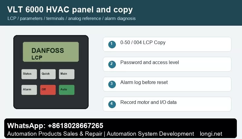
The VLT6000 HVAC LCP has display lines, menu keys, Change Data, OK, Cancel, Hand/Auto/Stop Reset keys and green ON, yellow WARNING and red ALARM indicators. Parameters 007-010 select display readouts, while 600-605 show operating hours, power-ups, overtemperature count and overvoltage count.
Use the status display first to check frequency, current, reference, direction, terminal state and alarm number. Use the quick menu for motor data, acceleration/deceleration and basic limits. Use the main menu for I/O, analog scaling, protection, bus communication and advanced functions.
VLT6000 uses parameter 004 LCP Copy. Stop the drive, ensure the operating mode is suitable, copy parameters into the LCP, then write them back to the replacement drive. After a control board or power board replacement, verify motor voltage, current, frequency, min/max frequency and HVAC application functions.
Parameter copying is useful for replacement drives and repeat machines. Before copying, record motor nameplate data, start source, reference source, terminal functions, relay functions, brake settings, communication address and alarm action. If the new drive rating is different, do not copy all parameters blindly.
Access Restriction and Password Recovery
Use LCP key permission and menu access settings to prevent wrong edits. Keep start, stop, reset and status readout available for operators, while protecting input group 300, communication group 500, operating data group 600 and motor nameplate settings.
In service work, divide access into three levels: operators may start, stop, reset and view status; maintenance staff may read alarm logs and terminal states; commissioning engineers may edit motor, I/O, reference, communication and protection parameters. If a drive is locked, try the valid password first. If initialization is unavoidable, back up or photograph all available data before restoring defaults.
External Forward/Reverse Terminal Control
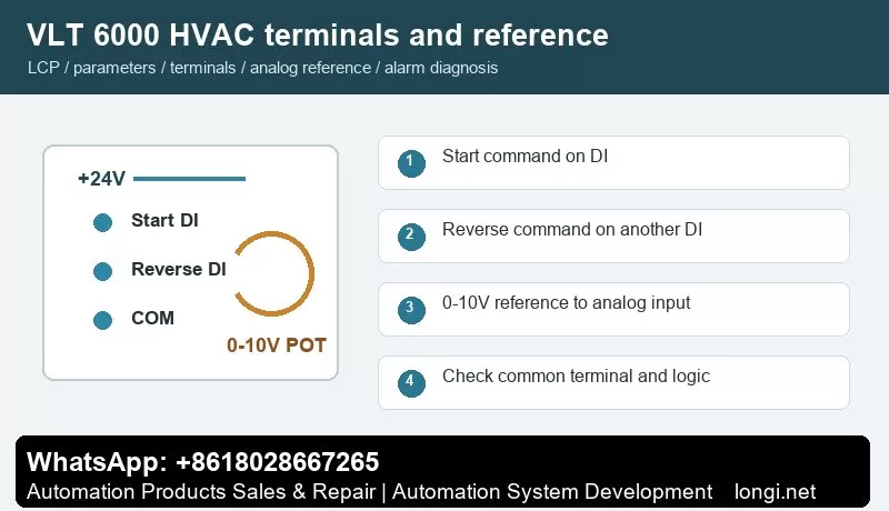
Mains connects to 91/92/93, motor to 96/97/98 and PE to 94/95/99. Digital inputs include terminals 16-19, 27, 29, 32 and 33. Terminal 27 is often used for start enable or interlock. Use one DI for start and another DI for reverse direction.
Use one digital input for start and another for reverse direction. Confirm +24 V, common terminal and input logic with a meter before connecting PLC outputs, switches or relays. After wiring, watch the terminal state on the LCP before running the motor. Test at low speed first, especially on pumps, fans, conveyors and spindle applications.
External Potentiometer Speed Reference
Voltage analog inputs 53/54 support 0-10 V and terminal 60 supports 0/4-20 mA. For potentiometer speed control, wire +10 V, terminal 53 and common in a three-wire circuit. Parameters 308, 309 and 310 define terminal 53 function, low scaling and high scaling.
A potentiometer reference only works correctly when the hardware input type, reference source, low/high scaling and frequency limits match. Measure the analog input at minimum and maximum position. If the drive reports wire break or the speed is nonlinear, check common wiring, shield grounding, voltage/current selection and low/high scaling before replacing the control board.
Fault Codes and Troubleshooting
- Warning 5/6, DC Link Voltage High/Low: inspect mains supply, braking process, deceleration time and load inertia.
- Overcurrent, Short Circuit or Earth Fault: after power-off, test motor and output cable insulation.
- External Fault 60: the interlock or external safety chain is open. Check terminal 27 and the external interlock contact.
- Overtemperature: check air path, heatsink dust, fans, ambient temperature and installation clearance.
- Phase Loss or Supply Abnormality: inspect terminals 91/92/93, input fuses, contactor and phase balance.
- Blank LCP or Disabled Keys: inspect control power, LCP cable, keypad restriction settings and control board.
- Communication Fault: check RS485 polarity on 68/69, shield grounding, protocol parameter 500 and master polling.
When troubleshooting, record the alarm number, frequency, current and DC link voltage at the moment of trip. If the drive runs without load but trips with load, focus on mechanical load, ramp time and motor data. If it trips without a motor, check output stage, brake circuit, internal supply and control board.
Field Checklist
- Before power-on: input voltage, grounding, motor insulation, brake resistor and cooling path.
- After power-on: panel status, terminal state, alarm log and access level.
- Before running: motor nameplate, command source, reference source, speed limits and ramps.
- Terminal control: test start, reverse, reset and interlock one by one.
- Analog reference: measure the actual signal and then set low/high scaling.
- Before delivery: save a parameter backup and document modified parameters and password policy.
Conclusion
The correct way to use the VLT 6000 HVAC manual is simple: use the panel to confirm status, parameter copy for backup and recovery, access restriction to prevent wrong edits, digital inputs for command logic, analog scaling for speed range, and alarm logs for troubleshooting direction.