
1. Introduction
In industrial motor drive applications, especially in textile, sewing, packaging, and light mechanical equipment, one of the most frequently misdiagnosed problems is “motor unable to self-start under inverter control but able to run once externally assisted”.
This case study is based on a real field troubleshooting scenario involving an AT900 series vector VFD (0.75–11kW class) controlling a sewing machine drive system. The system initially presented unstable starting behavior, requiring mechanical assistance via clutch engagement. After systematic diagnosis, the root cause was identified as an intermittent phase loss caused by an aging main contactor/fuse assembly.
The final resolution restored stable and smooth operation without vibration, confirming correct VFD behavior and motor integrity.
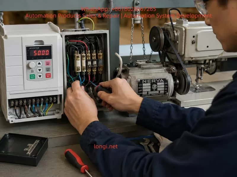
2. System Overview
The drive system consists of:
- AT900 series high-performance vector inverter (SVC control mode)
- Three-phase induction motor (~0.7–2.2kW class typical for sewing machines)
- Mechanical clutch coupling system
- Old-generation main contactor and fuse assembly
- Direct inverter-to-motor wiring (no encoder feedback)
According to AT900 technical specifications, the inverter supports:
- Sensorless vector control (SVC)
- V/F control modes
- Adjustable torque boost (0.1%–30%)
- Starting torque up to 150% depending on configuration
3. Initial Failure Symptoms
The operator reported:
- Motor does not start autonomously under RUN command
- If the clutch is manually engaged (mechanical rotation applied), motor runs normally
- When RUN is triggered, frequency rises smoothly from 0Hz → 15Hz
- Motor never reaches stable self-start torque region
- Changing torque boost (P04.01) and overload gain (P10.01) had no effect
Additionally:
- Motor could not self-start even when unloaded (belt removed test)
- Behavior was consistent but intermittent in severity
This symptom pattern strongly indicated a starting torque deficiency or phase imbalance condition, not a parameter tuning issue.
4. Critical Diagnostic Breakthrough
The decisive observation was:
Motor starts normally when externally rotated, but fails to self-start.
This is a classic signature of:
- Phase loss (single-phase operation under load)
- Intermittent contactor failure
- High contact resistance in one phase path
- Unequal phase voltage delivery to motor terminals
Such conditions reduce rotating magnetic field symmetry, preventing torque generation at zero speed.
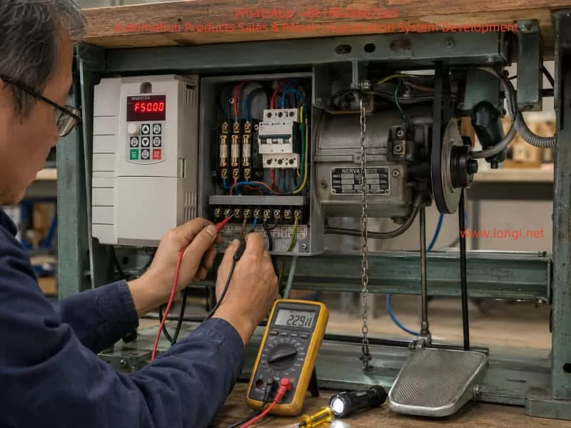
5. Electrical Measurements
After correction and stabilization, measured values were:
- Motor phase resistances:
- 19.7 Ω / 18.9 Ω / 19.7 Ω
- Cable/inverter-to-motor resistance:
- ~0.2 Ω (excellent continuity)
Interpretation:
| Parameter | Status |
|---|---|
| Motor winding symmetry | Acceptable (±4% deviation) |
| Cable integrity | Excellent |
| Inverter output | Normal |
| Historical issue | External phase interruption |
The winding values confirmed the motor itself was healthy. Therefore, the fault had to be upstream of the motor terminals.
6. Root Cause Analysis
The final confirmed root cause was:
Intermittent missing phase caused by an aged main contactor / fuse assembly
Mechanism of failure:
Old contactor systems typically suffer from:
- Oxidized silver alloy contacts
- Arc erosion at switching points
- Thermal expansion loosening internal pressure
- Intermittent phase dropout under load
- High resistance phase causing voltage imbalance
Under VFD operation, this leads to:
- One phase voltage drop or distortion
- Weak rotating magnetic field
- Zero-speed torque collapse
- Failure to self-start
- Motor only operates when externally “forced into motion”
Once rotating, back-EMF stabilizes the field, allowing operation.
7. Why Parameter Changes Failed
Attempts were made to adjust:
- Torque boost (P04.01)
- Motor overload gain (P10.01)
However, these parameters only affect:
- Low-frequency voltage compensation
- Thermal protection scaling
- SVC torque estimation correction
They cannot compensate for missing or unstable phase supply.
From AT900 control logic:
- Torque generation depends on balanced three-phase voltage vector synthesis
- Phase imbalance cannot be corrected by software gain alone
Thus, all tuning attempts were logically ineffective.
8. Final Corrective Action
The site implemented:
Hardware replacement
- Replacement of old contactor/fuse assembly
- Restoration of stable three-phase supply path
System verification
- Balanced phase continuity confirmed
- Direct inverter-to-motor wiring validated
- No external switching elements remaining
9. Final Performance Result
After correction:
- Motor starts reliably every time
- Smooth acceleration curve
- No vibration during low-speed operation
- Correct rotational direction
- Stable sewing machine mechanical operation
This confirms:
✔ VFD control system is healthy
✔ Motor insulation and windings are healthy
✔ Mechanical system is properly aligned
✔ Fault was purely upstream electrical distribution
10. Engineering Lessons Learned
10.1 Phase integrity is more important than parameter tuning
In VFD systems, hardware phase continuity is foundational. Any imbalance directly affects:
- Torque production
- Startup stability
- Current waveform symmetry
10.2 “Push-start symptom” is a diagnostic signal
If a motor:
- Fails at zero speed
- Runs normally after external rotation
Then likely causes are:
- Phase loss
- Voltage imbalance
- Incorrect wiring topology
- Weak starting flux condition
10.3 Do not modify VFD parameters before electrical verification
This case confirms a common diagnostic mistake:
Adjusting torque, frequency, and protection parameters without confirming power integrity leads to false troubleshooting cycles.
10.4 Mechanical clutch systems can mask electrical faults
The clutch in this system:
- Masked inability to self-start
- Allowed motor to bypass zero-speed torque requirement
- Created illusion of “weak torque setting”
11. AT900 Series Control Insight
This inverter family uses:
- Sensorless vector control (SVC)
- Voltage vector synthesis based on phase stability
- Torque estimation dependent on current feedback consistency
Therefore:
- Any upstream phase distortion directly disrupts vector calculation
- Protection systems may not immediately trigger fault codes
- Symptoms appear as “soft failure” rather than hard trip
12. Conclusion
This case demonstrates a classic but often misdiagnosed industrial fault:
A motor that cannot self-start under VFD control is not always a tuning problem — it is frequently a power integrity problem upstream of the drive.
The final resolution required:
- Rejecting parameter-centric diagnosis
- Performing hardware continuity validation
- Identifying intermittent phase loss in aging switching components
- Replacing degraded contactor/fuse assembly
Once corrected, the system returned to full performance with:
- Stable torque at low frequency
- Smooth acceleration
- Correct direction control
- Fully reliable restart behavior
13. Practical Recommendation for Engineers
When encountering similar cases:
- Do NOT increase torque boost blindly
- Always verify:
- Phase-to-phase voltage balance
- Contactors / fuses / connectors condition
- Continuity under load, not only static measurement
- Test motor behavior:
- With load disconnected
- With external rotation assistance
- Only then proceed to VFD parameter tuning