
1. Overview of the Fault Symptom
The ABB ACS550 is a widely used general-purpose variable frequency drive in industrial automation. It is commonly installed on fans, pumps, conveyors, trimming machines, packaging machines, textile equipment, woodworking machinery, and many other types of automated production equipment. Because the ACS550 provides flexible digital inputs, analog control, run interlock logic, and protection functions, many machine builders integrate external emergency stop circuits, safety doors, thermal relays, PLC run-enable signals, and other safety-related conditions into the drive’s control logic.
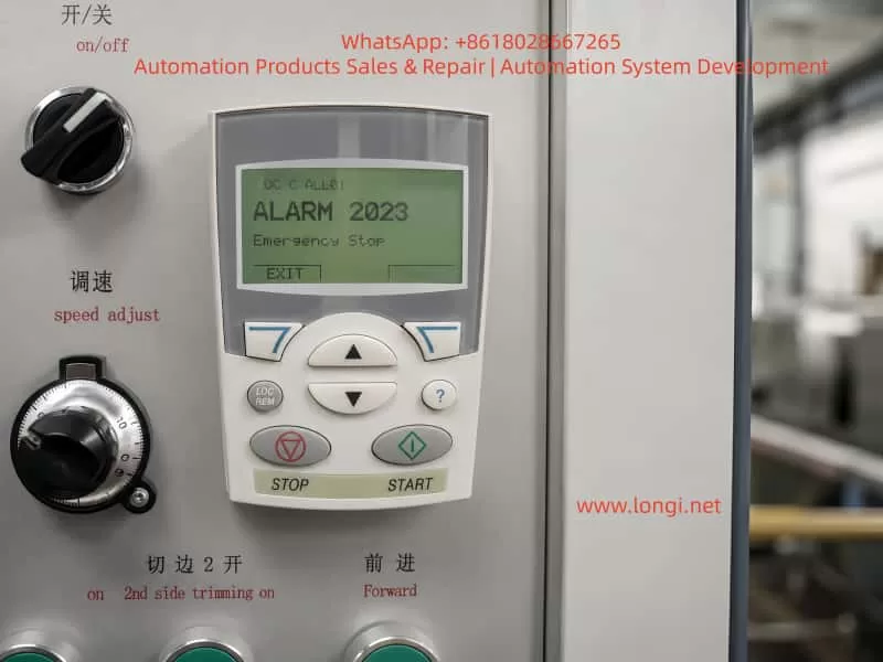
A common field fault is that the ACS550 keypad displays:
ALARM 2023
Emergency Stop
This alarm means that the drive has detected an active emergency stop condition. In practical terms, the drive believes that the machine is not allowed to run, or that an external safety circuit is commanding the drive to stop.
It is important to understand that Alarm 2023 does not automatically mean the inverter power section is damaged. In most cases, it is related to the external control circuit, digital input status, safety relay, PLC interlock, 24 V control supply, or parameter configuration.
A frequent mistake in the field is to check only the red emergency stop button. If the button is not pressed, some technicians immediately assume that the drive is faulty. This is not a correct diagnostic approach. On many industrial machines, the emergency stop button is only one part of a larger safety chain. The emergency stop signal may pass through safety relays, intermediate relays, PLC inputs and outputs, terminal blocks, and finally reach one of the ACS550 digital inputs.
Therefore, when troubleshooting ACS550 Alarm 2023, the correct method is not simply to ask whether the emergency stop button is released. The correct method is to confirm whether the ACS550 actually receives the correct run-enable or emergency-stop-reset signal.
2. What Alarm 2023 Really Means
Alarm 2023 on an ABB ACS550 indicates that the emergency stop function is active. This is generally a control logic alarm rather than a typical power-stage fault such as overcurrent, DC bus overvoltage, undervoltage, IGBT short circuit, or motor insulation failure.
From a maintenance perspective, the alarm can be understood in three layers.
First, the drive is not allowed to run under the current condition. Even if the START button is pressed, the ACS550 may not output normally.
Second, the drive has detected an external control input state that corresponds to emergency stop, safety stop, or run inhibit.
Third, the root cause is usually found in the control circuit, digital input wiring, parameter setting, or input hardware circuit.
This distinction is very important. If Alarm 2023 appears, replacing the inverter immediately is usually not the correct first step. The external safety chain and input logic must be checked before judging the drive itself as defective.
3. Common Emergency Stop Control Structures on ACS550 Systems
Different machine manufacturers may wire the ACS550 in different ways. However, in industrial equipment, the emergency stop signal usually follows one of the following structures.
3.1 Emergency Stop Button Directly Connected to a Drive Digital Input
In a simple control system, the emergency stop button may be wired directly to one of the ACS550 digital inputs. The button normally uses a normally closed contact. When the emergency stop button is released, the digital input receives the correct signal. When the button is pressed, the circuit opens and the drive stops or reports an emergency stop alarm.
This structure is simple, but it is usually found only on smaller machines or systems with lower safety requirements.
3.2 Emergency Stop Button Connected Through an Intermediate Relay
In many machines, the emergency stop button does not go directly into the drive. Instead, it controls an intermediate relay. The relay output contact then provides a signal to the ACS550 digital input.
In this structure, the emergency stop button may be mechanically normal, but the drive can still receive an emergency stop signal if the relay coil is not energized, the relay contact is oxidized, the relay base is loose, or the wiring between the relay and the drive is damaged.
Therefore, checking only the button is not enough. The relay output contact must also be checked.
3.3 Emergency Stop Circuit Connected Through a Safety Relay
On machines with safety doors, dual-channel emergency stops, safety light curtains, guard switches, or protective covers, the emergency stop circuit usually enters a safety relay or safety controller. Only when the safety relay is reset and all safety channels are valid will the relay output a safety-permit signal to the PLC or the drive.
In this structure, the emergency stop button may already be reset, but the safety relay may still be in a fault or unreset state. The safety relay may require manual reset, dual-channel consistency, correct power-up sequence, or a closed safety door before it enables its output contacts.
When this type of system reports ACS550 Alarm 2023, the safety relay status LEDs must be checked carefully. The technician should verify power, input channels, reset status, output status, and fault indication.
3.4 PLC-Based Emergency Stop and Run-Permit Logic
On more advanced automated equipment, the emergency stop, safety door, thermal relay, air pressure switch, limit switch, and other interlock signals may first enter a PLC. The PLC then processes the machine logic and sends a run-enable or drive-enable signal to the ACS550.
In this case, the ACS550 is only the final actuator in the control chain. Alarm 2023 may appear because the PLC is not providing the run-permit signal. The cause may be a missing sensor condition, PLC program interlock, damaged PLC output, failed intermediate relay, incorrect 24 V signal, or wiring problem.
This is why the alarm must be analyzed as a system-level control issue, not only as a drive issue.
4. Why Alarm 2023 Can Remain Even When the Emergency Stop Button Is Normal
In many real field cases, the operator confirms that the emergency stop button is not pressed, but the ACS550 still displays Alarm 2023. This can happen for several reasons.
4.1 The Button Is Normal, but the Wiring Is Open
The emergency stop button may mechanically reset correctly, but the cable from the button to the terminal block, relay, PLC, or drive may be broken or loose. Industrial machines are subject to vibration, oil contamination, dust, and repeated maintenance work. Terminal screws may loosen, connectors may oxidize, and cable cores may break inside the insulation.
The correct check is not only to test the button contact. The signal must be traced all the way to the ACS550 digital input terminal.
4.2 The Safety Relay or Emergency Stop Relay Has Not Reset
After the emergency stop button is released, the safety relay may still remain in a tripped state. Some safety relays require a separate reset signal. Some require both safety channels to recover simultaneously. Some will not reset if one safety door or guard switch is still open.
If the safety relay output is not enabled, the ACS550 will not receive the correct permit signal, and Alarm 2023 may remain.
4.3 The 24 V Control Supply Is Missing or Abnormal
ACS550 digital inputs require a valid control voltage and reference. Depending on the machine design, the digital input signal may come from the drive’s internal 24 V supply, an external 24 VDC power supply, a PLC output, or an intermediate relay.
If the 24 V control supply is missing, weak, unstable, or if the 0 V reference is disconnected, the digital input state may become invalid. The operator may see that buttons and switches look normal, but electrically the ACS550 is not receiving the proper input level.
4.4 The Digital Input Common Terminal Is Incorrectly Wired
Digital inputs require both the input signal and the correct common reference. If the DI common, DCOM, COM, 0 V, or 24 V wiring is incorrect, the drive may not recognize the input even though voltage appears to be present somewhere in the control cabinet.
This problem is common after drive replacement, control cabinet rewiring, terminal strip repair, or parameter restoration. A technician may reconnect the signal wire but forget the correct common reference.
4.5 Parameters Have Been Changed
If ACS550 parameters have been changed, a digital input may have been assigned to emergency stop, run enable, start enable, or external fault. If the selected digital input is not wired correctly, the drive may continuously detect an invalid condition.
This is especially common when a second-hand drive is installed, a replacement drive is used, factory reset has been performed, or multiple people have adjusted the drive parameters.
For example, if an unused DI terminal is accidentally assigned as an emergency stop input, the drive may remain in Alarm 2023 because that DI never receives the required signal.
4.6 The ACS550 Digital Input Circuit Is Damaged
If the external circuit, voltage, relay contacts, common terminal, and parameter configuration are all confirmed to be correct, but the ACS550 input status still does not change, the digital input circuit may be damaged.
Possible causes include incorrect high-voltage wiring into a low-voltage input, short circuit, surge voltage, moisture contamination, terminal corrosion, damaged optocoupler, or failure in the control board input circuit.
This diagnosis should only be made after the external control signal has been fully verified at the drive terminals.
5. Correct Field Troubleshooting Sequence
The most efficient way to troubleshoot ACS550 Alarm 2023 is to work from outside to inside, from simple checks to detailed electrical verification, and from signal status to parameter logic.
Step 1: Confirm All Emergency Stop and Safety Devices
Check all emergency stop buttons on the machine, not only the one near the main control panel. Some machines have multiple emergency stops at different locations, including remote stations, conveyor ends, control cabinet doors, and operator stations.
Also check safety doors, guard switches, limit switches, safety light curtains, protective covers, pull-wire emergency switches, and thermal overload contacts.
A single open safety device can keep the ACS550 in emergency stop status.
Step 2: Check the Safety Relay or Intermediate Relay
Open the control cabinet and check whether the emergency stop relay, safety relay, or intermediate relay is energized.
If the relay has LED indicators, check the power indicator, input channel indicators, reset status, output indicators, and fault indication.
If the relay is not energized, measure the coil voltage. If the coil has no voltage, the upstream safety circuit is not complete. If the coil has correct voltage but the relay does not operate, the relay itself may be faulty. If the relay operates but its output contact does not close, the contact may be damaged or oxidized.
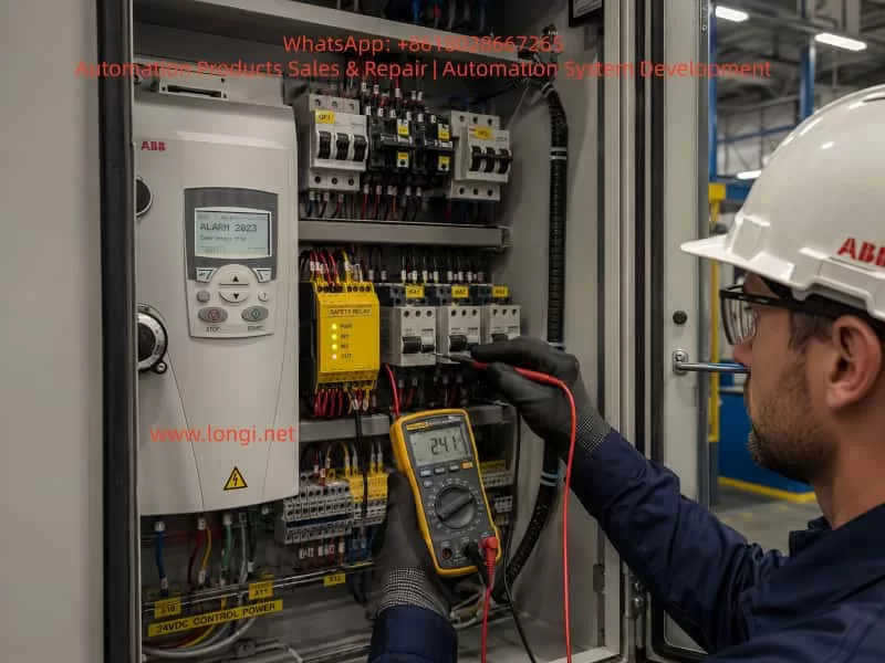
Step 3: Measure the ACS550 Digital Input Terminal Voltage
This is one of the most important steps. Identify which ACS550 digital input is assigned to emergency stop, run enable, or start enable. Then use a multimeter to measure the voltage between that DI terminal and the correct common terminal.
When the emergency stop circuit is reset, the input should have the correct valid level according to the drive configuration. When the emergency stop is pressed, the input state should change.
If the external device operates but the voltage at the ACS550 terminal does not change, the fault is in the external wiring or relay circuit.
If the voltage at the ACS550 terminal changes correctly but the drive input status does not change, the problem may be in the drive input circuit, common wiring, or parameter configuration.
Step 4: Check the ACS550 I/O Status on the Keypad
The ACS550 keypad can be used to view digital input status. The technician should check the ON/OFF status of DI1, DI2, DI3, DI4, DI5, and DI6.
This step is essential because measuring voltage at the terminal and confirming that the drive internally recognizes the input are not the same thing. The drive must actually detect the input state change.
If the emergency stop circuit is reset and the corresponding DI does not change to the expected state, the drive is still not receiving or recognizing the correct signal.
Step 5: Verify Parameter Configuration
If the digital input voltage and keypad I/O status appear normal but the alarm remains, the relevant parameters must be checked.
The technician should review parameters related to control macro, external command source, digital input assignment, emergency stop, run enable, start enable, external fault, and input polarity.
Parameter checking must be done carefully. The original parameters should be recorded before any changes are made. If possible, compare the settings with the machine electrical drawing, commissioning record, or another identical machine.
Blindly disabling emergency stop or run-enable functions is not an acceptable repair method.
Step 6: Evaluate Possible Drive Control Board or Input Damage
Only after external wiring, control voltage, relay contacts, common terminal, and parameter configuration have been confirmed should the technician consider a faulty ACS550 control board or digital input circuit.
Further verification may include assigning the function to another spare DI input, testing the same signal on another input, comparing with an identical drive, or inspecting the control board input components.
Any temporary reassignment of a safety-related input must be done by qualified personnel and must not compromise machine safety.
6. Important Measurement Notes
6.1 Do Not Measure Only the Button
Testing the emergency stop button alone is not enough. The drive does not know whether the button itself is good. The drive only knows whether the correct signal reaches its digital input.
Therefore, the signal must be traced from the button to the relay, from the relay to the terminal block, from the terminal block to the PLC or drive, and finally to the ACS550 DI terminal.
6.2 Pay Attention to Normally Open and Normally Closed Logic
Emergency stop circuits usually use normally closed contacts. In normal condition, the circuit is closed. When the emergency stop is pressed, the circuit opens.
However, the drive parameter logic may define whether an input is active high or active low. If the wiring logic and parameter logic do not match, the drive may interpret a normal condition as an emergency stop condition.
This type of logic mismatch is common after parameter changes or drive replacement.
6.3 Confirm the Source of the 24 V Signal
Some machines use the ACS550 internal 24 V supply for digital inputs. Others use an external 24 VDC power supply or PLC output. Before testing or shorting any input, the technician must confirm where the 24 V signal comes from.
Incorrectly mixing an external 24 V supply with the drive’s internal 24 V supply may damage the drive control terminal or PLC output.
6.4 Do Not Bypass the Emergency Stop Circuit Permanently
Some technicians may temporarily short the emergency stop input to make the drive run. This may help identify the fault range, but it creates a serious safety risk.
Emergency stop circuits protect personnel and equipment. On machines with cutters, conveyors, winders, fans, presses, or moving mechanisms, bypassing emergency stop protection can cause injury or equipment damage.
If a temporary bypass is required for diagnosis, it must be performed only under controlled conditions, with the mechanical load isolated, personnel kept away from moving parts, and the original safety circuit restored immediately after testing.
7. Typical Field Case Analysis
A machine using an ABB ACS550 cannot start. The keypad displays Alarm 2023 Emergency Stop. The operator checks the emergency stop button on the control panel and confirms that it is not pressed. The button is rotated and reset several times, but the alarm remains.
At this point, it would be incorrect to conclude immediately that the inverter is damaged. The better approach is to inspect the complete safety chain.
After opening the control cabinet, the technician may find that the emergency stop button does not connect directly to the drive. Instead, it enters a safety relay first. The safety relay output goes to the PLC, and the PLC outputs a run-permit signal to one digital input of the ACS550.
This means that the ACS550 alarm does not necessarily indicate a defective emergency stop button. It indicates that the final run-permit signal has not reached or has not been recognized by the drive.
Possible findings include:
The safety relay has not reset.
The safety relay output contact is not closed.
The PLC has not received the safety relay feedback.
The PLC does not output the run-permit signal.
The intermediate relay contact between the PLC and ACS550 is oxidized.
The ACS550 DI terminal wire is loose.
The 24 V supply is normal, but the DCOM common wire is open.
A parameter has been changed, assigning emergency stop to an unwired DI terminal.
By analyzing the signal chain in this way, the technician can avoid unnecessary drive replacement and locate the real control-circuit fault more efficiently.
8. Difference Between Alarm 2023 and Other Start-Inhibit Alarms
On the ACS550, there are several alarms and conditions that may prevent the drive from starting. These include emergency stop, start enable missing, run enable missing, external fault, and other interlock-related conditions.
Although the symptom may be similar, the causes are different.
Emergency Stop indicates that the emergency stop or safety stop function is active.
Start Enable missing usually indicates that a start-permission input is not satisfied.
External Fault indicates that an external device is reporting a fault to the drive through a digital input.
Run Enable problems indicate that the drive’s run-permit condition is not met.
Therefore, troubleshooting must be based on the exact alarm code and message shown on the keypad. Not all “drive cannot start” cases should be treated as the same fault.
For Alarm 2023, the key point is that the drive believes the emergency stop state is active. If the physical button is not pressed, the next focus should be the safety relay, PLC logic, digital input status, 24 V supply, common terminal, and parameter assignment.
9. Recommended Diagnostic Logic for Technicians
When dealing with ACS550 Alarm 2023, technicians should follow a clear diagnostic logic.
First, do not immediately assume that the drive is damaged. Alarm 2023 is more likely related to external control signals than to the power section.
Second, do not rely only on the visual condition of the emergency stop button. A released button does not guarantee that the ACS550 has received the correct safety-permit signal.
Third, focus on the digital input assigned to emergency stop or run enable. Once this DI point is identified, the technician can determine whether the problem is outside the drive or inside the drive.
Fourth, combine voltage measurement with keypad I/O status. If voltage is missing at the terminal, the problem is external. If voltage is present but the drive input status does not change, the problem may be in the input circuit, common wiring, or parameter logic.
Fifth, check parameters carefully. Parameter errors can create a false emergency stop condition. However, safety-related functions should not be disabled casually.
Sixth, never use a permanent bypass as a repair solution. Emergency stop is part of the machine safety system and must be restored before normal operation.
10. Practical Field Checklist
The following checklist can be used during troubleshooting:
- Confirm that all emergency stop buttons are fully reset.
- Check safety doors, covers, guard switches, light curtains, and limit switches.
- Check whether the emergency stop relay or safety relay is energized.
- Confirm whether the safety relay requires manual reset.
- Measure the 24 V control supply.
- Check 0 V, DCOM, COM, and digital input common wiring.
- Measure the voltage at the relevant ACS550 DI terminal.
- Check whether the corresponding DI status changes on the keypad.
- Review parameters related to emergency stop, start enable, run enable, external fault, and control macro.
- Confirm whether the drive has been replaced, reset, or reprogrammed recently.
- Check whether the PLC is outputting the run-permit signal.
- Inspect intermediate relay contacts for oxidation or poor contact.
- Check terminal blocks, connectors, cable numbers, and wiring tightness.
- If all external signals are correct, evaluate possible ACS550 digital input or control board damage.
This checklist helps narrow the fault from the complete safety circuit to the exact drive input point.
11. Maintenance Conclusion
ABB ACS550 Alarm 2023 “Emergency Stop” means that the drive has detected an active emergency stop or safety stop condition. In most cases, the root cause is not a damaged inverter power stage, but an issue in the external emergency stop chain, safety relay, PLC interlock, 24 V control supply, digital input wiring, common terminal, parameter logic, or the drive’s digital input circuit.
When the emergency stop button appears normal, the emergency stop circuit should not be considered fully cleared. The key question is whether the correct reset or run-permit signal has actually reached the ACS550 digital input and whether the drive has recognized it through its I/O status.
If there is no correct voltage at the ACS550 DI terminal, the fault is usually in the external control circuit. If the terminal voltage is correct but the drive input status does not change, the cause may be incorrect common wiring, input circuit failure, or control board damage. If the input status is correct but the alarm remains, parameter logic and run interlock configuration should be checked carefully.
The correct troubleshooting strategy is to trace the signal step by step, verify the digital input status, confirm the parameter assignment, and only then judge whether the drive itself is faulty. Blindly replacing the drive or bypassing the emergency stop circuit may create unnecessary cost and serious safety risk.
A safe and reliable repair requires both electrical diagnosis and respect for the machine safety system. Only after the external safety chain, ACS550 input status, and parameter logic are fully verified can Alarm 2023 be resolved accurately and the equipment returned to stable operation.