
Foreword
The SR10000 series recorders produced by Yokogawa Electric Corporation are high-performance, multi-channel data recording devices widely used in industrial process control, laboratory monitoring, and other fields. This guide aims to systematically organize the official manual, extract key operations, and help users quickly master and effectively apply the recorder.
Chapter 1: Device Overview and Core Concepts
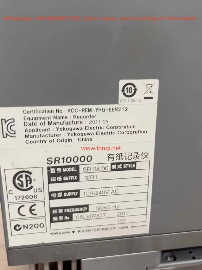
1.1 Models and Basic Parameters
- Model Classification: Pen-type (SR10001 – SR10004) and dot-matrix type (SR10006).
- Measurement Cycle: The pen-type has a fixed measurement cycle of 125 ms, while the dot-matrix type depends on the A/D integration time.
- Input Channels: Correspond to the number of pens or dots in the model. Unused channels can be set to “Skip”.
1.2 Two Operating Modes
- Setting Mode: Press and hold the MENU key for 3 seconds to enter and set daily parameters.
- Basic Setting Mode: In the setting mode, press and hold the △ and ▽ keys simultaneously for 3 seconds to enter for in-depth system configuration.
- Important Note: The basic setting mode cannot be accessed during recording.
1.3 Core Concepts
- Range Type: Such as thermocouple type K, DC voltage 2V, etc., with fixed measurable ranges.
- Input Range: Specify the actual measurement range within the measurable range.
- Recording Range: On the recording paper, a width of 100 mm represents 0% to 100% of the input range.
- Scale Calculation: Linearly convert voltage signals into actual physical units.
Chapter 2: Detailed Explanation and Configuration of Measurement Input Functions
2.1 Input Type and Range Setting
- Operation Path: Setting mode → RANGE, select the channel and input type, and set the range values.
2.2 Input Signal Processing Functions
- Filter (Pen-type Models): A low-pass filter to smooth signals.
- Moving Average (Dot-matrix Models): Calculate the average of consecutive sampled values.
- A/D Converter Integration Time: Suppress power frequency interference.
2.3 Advanced Calculation and Compensation Functions
- Bias: Add a fixed offset to the measured value.
- Input Value Calibration (/CC1 Optional Accessory): Multi-point broken-line calibration.
- Thermocouple Cold Junction Compensation: Compensate for errors caused by cold junction temperature changes.
- Thermocouple/1 – 5V Open-circuit Detection: Detect signal disconnections and trigger alarms.
Chapter 3: Alarm Function Configuration and Management
3.1 Alarm Types and Setting
- Operation Path: Setting mode → ALARM, select the channel and alarm number, and set the alarm type and value.
3.2 Advanced Alarm Settings
- Alarm Hysteresis: Prevent frequent alarm operations.
- Alarm Output Relay Action: Select the action mode of the relay when an alarm occurs.
- Diagnostic Output: Trigger relay 101 when the recorder fails.
Chapter 4: Comprehensive Analysis of Recording and Printing Functions
4.1 Curve Recording
- Pen-type Models: Continuous recording with fixed colors.
- Dot-matrix Models: Periodic dot-matrix recording, with adjustable recording cycles and colors.
4.2 Paper Feed Speed and Area Recording
- Paper Feed Speed: Setting mode → CHART, select the speed gear.
- Area Recording: Limit the recording range for specific channels.
4.3 Printing Output Functions
- Timed Printing: Print at set time intervals.
- Alarm Printing: Print when an alarm occurs or is cleared.
- Information Printing: Print preset information triggered by manual or remote signals.
- Manual Printing, List Printing, and Setting List Printing: Meet different printing needs.
4.4 Advanced Recording Functions
- Partial Compression/Expansion Recording: Compress or expand a specific part of the recording range for display.
- Phase-synchronized Recording (Pen-type Models): Ensure that the recording times of multiple pens are aligned.
Chapter 5: Maintenance, Calibration, and Troubleshooting
5.1 Regular Inspection and Cleaning
- Inspection Items: Display, recording, and printing functions, and the remaining amount of recording paper.
- Cleaning: Regularly clean the transmission shaft of the writing pen holder or the printing pen holder.
5.2 Calibration
- Calibration Instruments: High-precision standard signal generators, etc.
- Calibration Steps: Connect the device, warm it up, input standard signals, and check the displayed and recorded values.
5.3 Pen Position/Dot Position Adjustment
- Pen-type Models: Basic setting mode → P_ADJ, adjust the left and right end positions.
- Dot-matrix Models: Adjust the central hysteresis, left end, and right end positions in sequence.
5.4 Troubleshooting
- Check Error Messages: The display shows error codes, which can be solved by referring to the manual.
- Use Troubleshooting Flowcharts: Diagnose common problems.
- Common Problem Checkpoints: Power supply, input signals, recording paper/pens/ribbons, key locks/custom menus.
Chapter 6: Introduction to Optional Accessories and Advanced Functions
- Communication Function (/C3, /C7): Remote monitoring and data acquisition.
- Alarm Output Relays (/A1, /A2, /A3): Provide more relay output points.
- Remote Control (/R1): Control recorder functions with external signals.
- Title Printing (/BT1): Enhance batch printing functions.
- Input Value Calibration (/CC1): High-precision multi-point broken-line calibration.
- Extended Input (/N1, /N3): Support more thermocouple and thermistor types.
Chapter 7: Summary and Best Practice Recommendations
- Plan Before Setting: Clearly define the setting requirements for each channel.
- Make Good Use of the Function Setting Wizard: It provides great help for complex configurations.
- Pay Attention to Signal Quality: Ensure correct wiring, grounding, and filtering.
- Use Printing Functions Reasonably: Set printing intervals and event markers according to needs.
- Establish a Maintenance Calendar: Regularly clean, inspect, and calibrate.
- Operate Safely: Perform wiring and maintenance after power-off and comply with safety signs.