
1. Introduction: Why the F7 Saturation Fault Is a Critical Warning in VACON NXS Drives
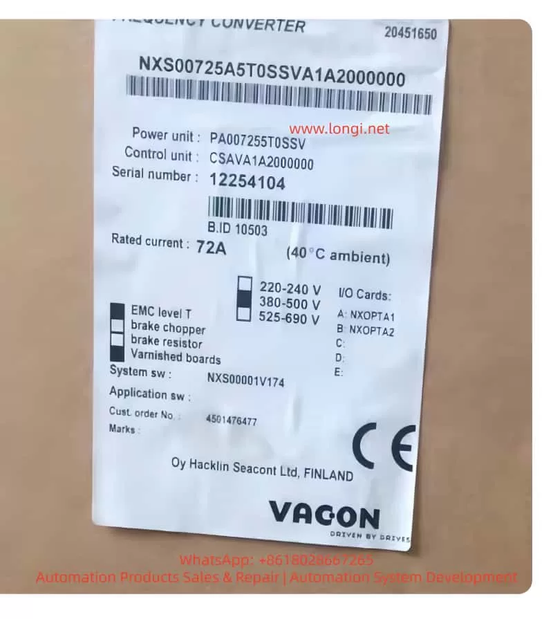
The VACON NXS series frequency inverter, manufactured by VACON, has long been recognized in industrial automation for its robust power stage design, stable vector control performance, and suitability for continuous-duty applications such as pumps, fans, conveyors, extruders, and compressors.
However, among all fault codes encountered in long-term operation or post-repair scenarios, F7 – Saturation stands out as one of the most critical and hardware-oriented alarms. Unlike common operational faults such as overcurrent, overvoltage, or undervoltage, F7 is not a parameter-level or control-logic-level fault. Instead, it is a direct hardware protection event originating from the power stage and gate drive circuitry.
This article provides a comprehensive, engineering-level explanation of the F7 Saturation fault in VACON NXS drives, covering its semiconductor physics background, internal detection logic, typical field symptoms, root causes, diagnostic workflow, and professional repair recommendations. The goal is to help third-party readers—maintenance engineers, repair technicians, system integrators, and equipment owners—correctly interpret and handle this fault without causing secondary damage.

2. Fault Description and Panel Indication
When the fault occurs, the keypad typically displays:
F7 Saturation
T1 + T16
The information conveyed here is highly specific:
- F7 – Saturation
Indicates that the inverter has detected an abnormal saturation condition in one or more IGBT devices. - T1 / T2 / T3
Identifies the affected phase (commonly corresponding to U / V / W phase IGBT groups). - T16
Denotes that the fault originates from the power unit or IGBT submodule protection layer, not from software logic.
This level of detail already tells an experienced engineer that the issue lies inside the power conversion stage, not in external wiring, parameters, or communication.
3. Typical Field Symptoms of F7 Saturation
From accumulated service cases, the F7 fault usually presents with the following characteristics:
- Occurs immediately at power-up or at the very beginning of start command
- Independent of load – appears even with the motor disconnected
- Cannot be cleared permanently by reset or factory defaults
- Reappears instantly when attempting to start the inverter
These symptoms strongly indicate that the inverter’s protection system has detected a non-recoverable abnormal condition in the power devices.
4. Understanding “Saturation” from an IGBT Perspective
4.1 Normal IGBT Conduction Behavior
Under normal conditions, when the gate driver applies the correct gate voltage (typically around +15 V):
- The IGBT enters conduction
- The collector–emitter voltage (Vce) drops rapidly
- Power loss remains within the safe operating area
This state is often referred to as normal saturation conduction and represents healthy operation.
4.2 What “Abnormal Saturation” (DESAT) Means
A desaturation (DESAT) condition occurs when:
- The gate signal indicates the IGBT should be ON
- But Vce does not drop as expected and remains abnormally high
This indicates that the IGBT:
- Is damaged
- Is insufficiently driven
- Or is subjected to an internal or external fault preventing proper conduction
In response, the driver immediately classifies this as a dangerous condition, as continued operation would lead to catastrophic device failure.
VACON NXS drives implement hardware-level DESAT detection with extremely fast response times (microseconds), bypassing CPU decision logic entirely.
5. Internal Protection Logic of the VACON NXS
The simplified protection sequence is as follows:
- Control board issues PWM command
- Gate driver amplifies and isolates the signal
- Driver continuously monitors IGBT Vce (or equivalent DESAT signal)
- Abnormal saturation detected
- Gate drive is forcibly shut down
- Fault is latched and reported as F7 Saturation
Because this mechanism is implemented at the driver hardware level, it cannot be disabled, masked, or overridden by parameters.
6. Why the F7 Fault Cannot and Must Not Be Bypassed
One of the most dangerous misconceptions in inverter repair is attempting to suppress or bypass the F7 fault.
This is fundamentally unsafe because:
- F7 is not software-generated
- It directly protects the IGBT against destructive conditions
- Bypassing it allows uncontrolled current flow
The inevitable result is complete IGBT destruction, often followed by damage to:
- DC bus capacitors
- Gate driver circuits
- Rectifier stage
- PCB copper traces
From an engineering standpoint, any attempt to bypass F7 should be considered unacceptable practice.
7. Root Causes of F7 Saturation Faults
7.1 IGBT Module Failure (Most Common)
Typical causes include:
- Collector–emitter partial short
- Semiconductor aging
- Bond wire fatigue due to thermal cycling
- Localized junction overheating
Characteristics:
- Usually affects one phase first
- Detectable via static electrical testing
7.2 Gate Drive Circuit Failure
The IGBT itself may be intact, but cannot be properly driven due to:
- Failed gate driver IC
- Open or drifted gate resistors
- Faulty DESAT detection diode
- Failed isolated power supply
- Damaged optocouplers or isolators
This category is especially common in previously repaired units.
7.3 Driver Board and Power Module Mismatch
VACON NXS series uses strictly matched driver boards and power modules:
- Different power ratings require different gate drive characteristics
- Incorrect matching leads to insufficient gate current or incorrect DESAT thresholds
The result is immediate F7 triggering.
7.4 External or Secondary Causes (Triggering Factors)
Examples include:
- Motor winding short circuits
- Output cable insulation failure
- Severe DC bus ripple due to aged capacitors
It is important to note that these factors do not cause F7 directly, but rather stress the IGBT until the protection activates.
8. Recommended Diagnostic Procedure (Professional Workflow)
Step 1: Safe Power Down
- Disconnect input power
- Wait at least 5 minutes
- Verify DC bus voltage has dropped below 50 V
Step 2: Static IGBT Testing
- Use multimeter diode/resistance mode
- Measure C–E and G–E junctions
- Any abnormal reading → replace the IGBT module
Step 3: Inspect Gate Driver Board
Focus on:
- Burn marks or discoloration
- Missing or replaced components
- Gate resistors and DESAT circuitry
- Isolation power supply integrity
Step 4: Verify Board Matching and Connections
- Confirm correct driver board model
- Inspect ribbon cables and connectors
- Check for oxidation or poor contact
Step 5: Eliminate External Factors
- Disconnect motor and output cables
- Perform no-load start attempt
- Persistent F7 confirms internal fault
9. Repair Strategy and Cost Control Considerations
9.1 When to Replace the Entire IGBT Module
Recommended if:
- Unit has long service history
- Multiple phases show abnormal behavior
- Visible thermal damage exists
Partial or single-device replacement is strongly discouraged.
9.2 When to Focus on Driver Board Repair
Appropriate when:
- IGBT tests normal
- Fault consistently points to a single phase
- There is a known repair history
9.3 Recommendations for Equipment Owners
- Do not repeatedly power up after F7 occurs
- Avoid “trial runs” or forced resets
- Engage qualified power-electronics repair specialists early
10. Conclusion: Understanding F7 Prevents Secondary Damage
The F7 Saturation fault in VACON NXS inverters is not mysterious, nor arbitrary. It is a direct, honest, and hardware-driven warning that the inverter’s power stage can no longer operate safely.
Ignoring it or attempting to bypass it invariably leads to more extensive damage and higher repair costs. Respecting it and applying a structured diagnostic approach allows the fault to be resolved within a controlled technical and economic framework.
Final Summary Statement
F7 Saturation in VACON NXS drives is a non-negotiable hardware protection triggered by abnormal IGBT conduction behavior. It cannot be disabled, cannot be masked, and must be resolved through proper power-stage and gate-drive repair.