
I. Operation Panel Functions and Basic Settings
1. Introduction to Operation Panel Functions
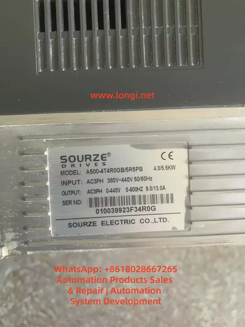
The operation panel of the Sourze A500/A500S frequency inverter is equipped with comprehensive control and display functions. Its interface is composed of the following elements:
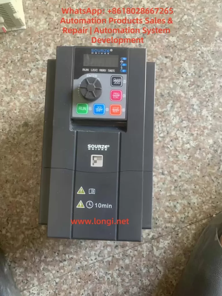
Indicator Light Area:
- Unit Indicator Lights (Hz/A/V/RPM/%): Display the current parameter units.
- Running Status Indicator Light (RUN): Green indicates the running state.
- Control Mode Indicator Light (L/D/C): Red indicates the current control mode (panel/terminal/communication).
- Direction Indicator Lights (FWD/REV): Red indicates the forward/reverse running states.
Digital Display Area: A 5-digit LED display that can show the set frequency, output frequency, monitoring data, and alarm codes.
Keyboard Buttons:
- PRG/ESC: Enter/exit the menu.
- ENTER: Confirmation key.
- +/-: Data increment/decrement.
- >: Cycle through displayed parameters.
- RUN: Running key.
- STOP/RESET: Stop/reset key.
- QUICK/JOG: Jog running/direction key.
2. Restoring Factory Parameters
Parameters can be initialized using function code A0-28:
- Enter parameter A0-28 (parameter initialization operation).
- Set it to 1: Restore factory parameters (excluding motor parameters, recorded information, and A0-20).
- Press the ENTER key to confirm and execute.
- The system will automatically return after completion.
3. Password Setting and Management
Setting a Password:
- Enter A7-50 (user password).
- Set it to a non-zero number (e.g., 12345).
- The password protection will take effect after returning to the status interface.
After Password Protection is Activated:
- Pressing the PRG key will display “—–“.
- The correct password must be entered to view and modify function codes.
- Incorrect entries will keep the display as “—–“.
Clearing the Password:
- Enter the menu using the password.
- Set A7-50 to 0.
- The password protection function will be canceled.
4. Parameter Access Restriction Settings
Parameter read-only mode can be set using function code E0-00:
- Enter E0-00 (function code read-only selection).
- Set it to 1: All function codes except E0-00 can only be viewed but not modified, preventing accidental parameter changes.
II. External Terminal Control and Speed Adjustment Settings
1. External Terminal Forward/Reverse Control
Hardware Wiring:
- Forward signal: Connect to the X(DI)2 terminal (default FWD function).
- Reverse signal: Connect to the X(DI)4 terminal (default REV function).
- Common terminal: COM terminal.
- 24V power supply: Provides power for external switches (optional).
Parameter Settings:
- A0-04 = 1: Select the terminal command channel.
- A5-01 = 1: Set X2(DI2) for forward running.
- A5-03 = 2: Set X4(DI4) for reverse running.
- A5-11 = 0: Select two-wire operation mode 1.
Control Logic:
- SW1 closed: Forward running.
- SW2 closed: Reverse running.
- Both closed or open: Stop running.
2. External Potentiometer Speed Adjustment
Hardware Wiring:
- Connect the three terminals of the potentiometer as follows:
- Upper terminal: +10V.
- Sliding terminal: AI1.
- Lower terminal: GND.
- Recommended potentiometer resistance: 1-5kΩ.
Parameter Settings:
- A0-06 = 2: Select AI1 as the main frequency source.
- A5-15 = 0.00V: Minimum input value for AI1.
- A5-16 = 0.0%: Corresponding to 0.0%.
- A5-17 = 10.00V: Maximum input value for AI1.
- A5-18 = 100.0%: Corresponding to 100.0%.
Calibration Adjustment:
- If the actual speed does not match the potentiometer position, adjust A5-15 to A5-18.
- Different AI curve characteristics can be selected via A5-45.
III. Fault Diagnosis and Handling
1. Common Fault Codes and Solutions
| Fault Code | Fault Name | Possible Causes | Solutions |
|---|---|---|---|
| Err12 | Undervoltage Fault | Input power voltage too low | Check if the power voltage is within the allowable range (±20%) |
| Err14 | Motor Overload | Excessive load or short acceleration time | Check the mechanical load and adjust the acceleration time in A0-23 |
| Err20 | Ground Short Circuit | Motor or cable insulation damage | Disconnect the inverter and check the motor insulation resistance (should be ≥5MΩ) |
| Err23 | Input Phase Loss | Three-phase input phase loss | Check the input power wiring |
| Err24 | Output Phase Loss | Motor or output cable fault | Check the output wiring and motor |
| Err27 | Communication Fault | Communication interruption or format error | Check the communication line and confirm the settings in A8-00 to A8-05 |
| Err28 | External Fault | External fault terminal activation | Check the external fault signal source |
| Err29 | Excessive Speed Deviation | Load突变 (sudden change) or inaccurate motor parameters | Retune the motor (A1-00 = 2) |
2. Fault Reset Methods
- Panel Reset: Use the STOP/RESET key.
- Terminal Reset: Set any X(DI) terminal function to 9 (fault reset).
- Automatic Reset: Set A9-11 (number of fault automatic resets) and A9-13 (reset interval time).
3. Fault Record Inquiry
Historical fault records can be viewed through the U0 group parameters:
- U0-00 to U0-03: The last 4 fault codes.
- U0-04 to U0-07: Corresponding running frequencies at the time of the faults.
- U0-08 to U0-11: Corresponding output currents at the time of the faults.
- U0-12 to U0-15: Corresponding DC bus voltages at the time of the faults.
IV. Advanced Function Applications
1. Multi-Speed Control
Setting Steps:
- A0-06 = 4: Select multi-speed as the frequency source.
- Set AC-00 to AC-15: Define 16 speed frequency values.
- Allocate X(DI) functions: Set A5-00 to A5-04 to 12 to 15 (multi-speed terminals 1 to 4).
Combination Control:
- Through 4 DI terminals, 16 states can be combined (binary 0000 to 1111).
- Each state corresponds to one of the frequency values in AC-00 to AC-15.
2. PID Control Application
Basic Settings:
- A0-06 = 6: Select PID as the frequency source.
- AA-00: Select the PID setpoint source (e.g., AI1).
- AA-03: Select the PID feedback source (e.g., AI2).
- AA-04: Set the PID action direction (0 for positive, 1 for negative).
Parameter Adjustment:
- AA-06: Proportional gain (increase to speed up response).
- AA-07: Integral time (decrease to eliminate steady-state error).
- AA-08: Derivative time (improve dynamic characteristics).
3. Frequency Sweep Function
Suitable for the textile and chemical fiber industries:
- Ab-00 = 0: Sweep amplitude relative to the center frequency.
- Ab-01 = 30.0%: Set the sweep amplitude.
- Ab-03 = 10.0s: Set the sweep frequency period.
- Ab-04 = 50.0%: Triangular wave rise time coefficient.
V. Maintenance and Upkeep
1. Daily Inspection Items
- Check for abnormal motor running sounds.
- Check motor vibration.
- Check the operation status of the inverter’s cooling fan.
- Check for overheating of the inverter.
2. Regular Maintenance
- Clean the air duct dust every 3 months.
- Check the tightness of screws.
- Check the wiring terminals for arc traces.
- Use a 500V megohmmeter to test the main circuit insulation (disconnect the inverter).
3. Replacement Cycles for Wear Parts
- Cooling fan: 2-3 years (depending on the usage environment).
- Electrolytic capacitor: 4-5 years.
4. Long-Term Storage Precautions
- Store in the original packaging.
- Power on every 2 years (for at least 5 hours).
- The input voltage should be raised slowly to the rated value.
Conclusion
The Sourze A500 series frequency inverter is powerful and flexible, capable of meeting various industrial application requirements through reasonable settings. This guide provides a detailed introduction to the entire process, from basic operations to advanced applications. It is recommended that users carefully read the relevant sections of the manual before use, especially the safety precautions. For complex application scenarios, it is advisable to contact the manufacturer’s technical support for professional guidance.