
1. Introduction
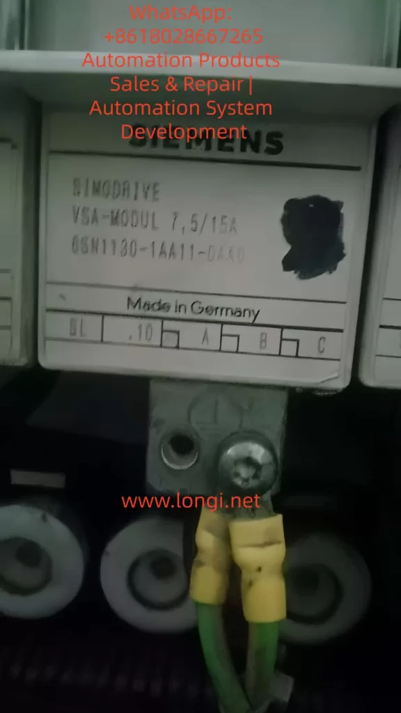
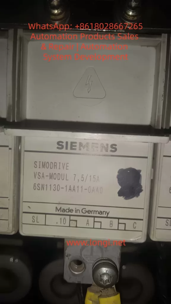
In the realm of industrial automation, Siemens SIMODRIVE 611 series is widely adopted in CNC machines, high-precision motion control systems, and complex production lines. Its modular, high-performance architecture makes it indispensable in advanced manufacturing systems.
Despite its robust design, the SIMODRIVE system can still exhibit critical faults during long-term operation or due to improper handling. One of the more complex and troublesome alarms is Error 0031, also known as “Internal Data Error.” This error suggests an inconsistency or corruption in the internal software structure of the drive system, which can render the drive inoperable if not handled properly.
This article provides a comprehensive analysis of the 0031 fault, including its possible causes, detection methods, on-site diagnosis techniques, corrective actions, and preventive strategies.
2. Overview of Error 0031
2.1 Error Definition
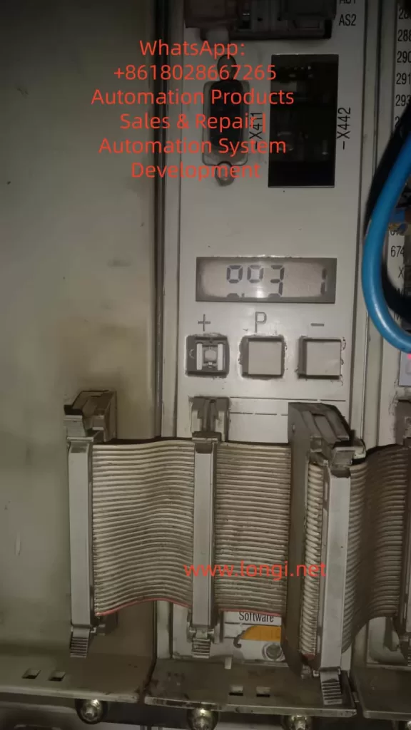
- Error Code: 031 (or 0031 in some systems)
- Description: Internal data error. Suppl. Info: %X
- Meaning:
The control module detects an inconsistency in its internal data structure. This typically involves corrupted element/block lists, illegal formats, or checksum mismatches. In such cases, the drive software is considered damaged or invalid and cannot proceed with normal operations.
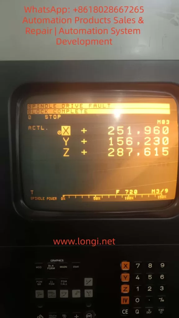
2.2 Typical Symptoms
- The drive does not start.
- LED indicators on the module show abnormal states (e.g., blinking yellow or solid red).
- The operator panel becomes inaccessible.
- The machine may enter an emergency stop condition.
3. Root Cause Analysis
3.1 Corruption in EEPROM or FLASH
The control module stores drive parameters, user configurations, and firmware in non-volatile memory (EEPROM or FLASH). Causes of corruption include:
- Sudden power outages or voltage spikes.
- Memory wear-out due to excessive write cycles.
- Faulty memory chips (common in older modules).
- Incorrect flashing or interruption during firmware download.
3.2 Hardware Malfunction in Control Module
- Damaged logic board components (e.g., MCU, CPLD, or memory ICs).
- Faulty voltage regulation (e.g., 5V, 15V power rails).
- PCB damage due to moisture, corrosion, or vibration.
- Cold solder joints or cracked vias.
3.3 Improper Firmware Download
- Incompatible or incorrect firmware version used.
- Incomplete software loading due to communication failure.
- Operator accidentally interrupted firmware download process.
3.4 External Communication Interference
- Noise or instability on PROFIBUS/PROFINET interface.
- Conflicting data packets from the connected PLC or HMI.
- Poor grounding or shielding on the communication cable.
4. On-Site Diagnostic Process
Step 1: Confirm Alarm Code
Methods to read the alarm:
- View error code on 7-segment display or HMI.
- Use Siemens SimoCom U or SimoCom A diagnostic tools.
- Query PLC diagnostics for drive status (if integrated).
Step 2: Inspect LED Status
| LED Behavior | Description |
|---|---|
| RED + RED | Severe internal error |
| YELLOW | Precharge or logic issue |
| GREEN solid | Normal operation |
If the power module supplies ~540VDC on the DC link, the drive hardware is likely receiving power.
Step 3: Measure Supply Voltages
Use a multimeter to check:
- +15V (P15) and 0V (N15)
- +24V control power
- Voltage deviation >±5% indicates power anomaly or damaged regulator.
Step 4: Check Cable Connections
- Verify X111/X121 signal cables are securely seated.
- Ensure X181 is correctly looped (NS1–NS2 shorted).
- For PROFIBUS: try disconnecting the bus to isolate possible communication faults.
5. Corrective Actions
5.1 Attempt Software Reload
Caution: Requires compatible firmware files and proper programming tools.
Recommended Tools: SimoCom U / A
Steps:
- Power on the system with the fault present.
- Connect PC to drive module using RS232 or serial-to-USB adapter.
- Launch SimoCom tool, select correct hardware version.
- Execute firmware update (may take several minutes).
- Reboot the system after flashing is complete.
If the reloaded software passes internal integrity checks, the fault should clear.
5.2 Replace the Control Module
If reloading fails or the module is unresponsive:
- Replace with the same model number (e.g., 6SN1118-0DG21-0AA1).
- Handle modules with ESD precautions.
- Confirm that option cards (e.g., PROFIBUS) are properly seated in the replacement.
5.3 Professional Repair and Refurbishment
If in-house repair is not feasible, consider sending the module to a certified repair center for:
- EEPROM/FLASH reprogramming.
- Replacement of failed ICs or logic chips.
- Optical inspection for PCB damage.
- Full parameter recovery (if backup available).
6. Preventive Measures
| Area | Recommendation |
|---|---|
| Power Supply | Install surge protection or isolation transformer to suppress electrical noise. |
| Operating Procedure | Avoid abrupt shutdowns or mid-download interruptions. Use proper software tools for updates. |
| Module Mounting | Secure the module firmly to prevent vibration or connector loosening. |
| Firmware Management | Maintain consistent firmware versions across identical drives. |
| Backup Policy | Regularly backup parameters and configuration data via SimoCom. |
| Communication Interface | Use galvanic isolation where needed to avoid interference from external devices. |
7. Conclusion
The 0031 internal data error in Siemens SIMODRIVE 611 systems is a critical fault that demands careful analysis and methodical troubleshooting. While it often points to memory or logic inconsistencies, the root cause may span from software corruption to hardware failure.
A systematic approach—starting from basic electrical checks, through software diagnostics, and ending in module repair or replacement—can effectively resolve this issue in most cases.
To prevent recurrence, establishing proper power conditioning, implementing backup strategies, and ensuring controlled firmware updates are essential steps. By doing so, users can maximize equipment uptime and ensure reliable long-term operation of SIMODRIVE 611 systems.