
Introduction
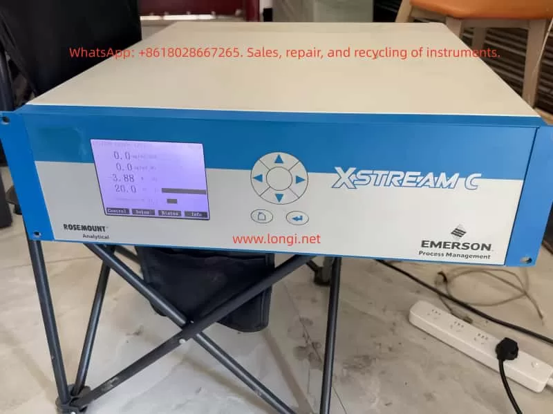
The Rosemount X-STREAM X2 series gas analyzers, introduced by Emerson Process Management, are high-performance instruments widely used in industrial process control, environmental monitoring, and safety protection. Renowned for their high precision, stability, and versatility, these analyzers are capable of simultaneously measuring multiple gas components, such as oxygen (O₂), carbon monoxide (CO), carbon dioxide (CO₂), and methane (CH₄). This user guide provides a comprehensive overview of the installation, operation, maintenance, and troubleshooting of the X-STREAM X2 series gas analyzers, enabling users to fully leverage their capabilities.
1. Product Overview
1.1 Product Features
- Multi-Parameter Measurement: The X-STREAM X2 series supports simultaneous measurement of various gas components.
- High Precision: Utilizes advanced sensor technology and signal processing algorithms to ensure accurate and reliable measurement results.
- Flexible Configuration: Offers multiple models and configuration options to meet diverse application needs.
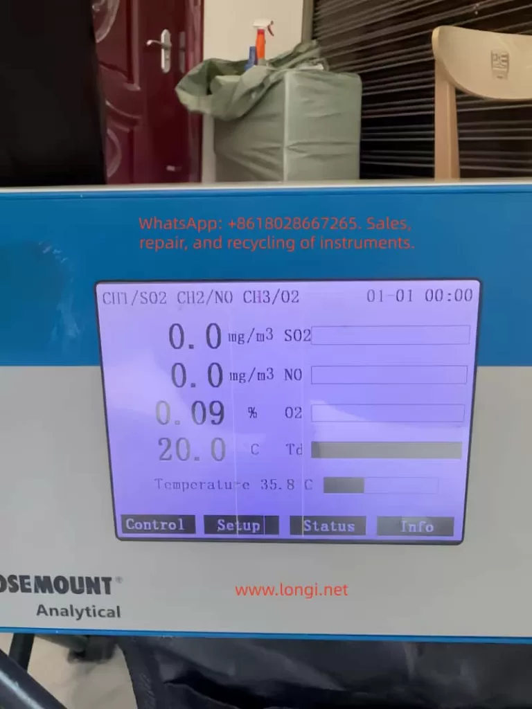
- User-Friendly Interface: Equipped with a large LCD display and intuitive user interface for easy operation and monitoring.
- Remote Communication: Supports industrial communication protocols like Modbus for remote monitoring and data transmission.
- Robust Design: Features a sturdy enclosure suitable for harsh industrial environments.
1.2 Application Areas
- Petrochemical Industry: Monitors gas composition during refining and chemical production processes.
- Iron and Steel Metallurgy: Monitors blast furnace gas, converter gas, and other industrial gases.
- Power and Energy: Used for combustion control in gas turbines and boilers.
- Environmental Monitoring: Atmospheric pollution monitoring and indoor air quality assessment.
- Safety Protection: Monitors combustible gas concentrations in flammable and explosive environments to prevent accidents.
2. Installation and Commissioning
2.1 Pre-Installation Preparation
- Confirm Specifications: Select the appropriate analyzer model and configuration based on application requirements.
- Check Accessories: Verify that all random accessories, including sensors, cables, and mounting brackets, are included.
- Environmental Assessment: Ensure the installation environment meets the analyzer’s operating requirements, avoiding extreme conditions such as high temperature, high humidity, and strong corrosion.
- Safety Measures: Adhere to safety operating procedures and wear necessary protective equipment during installation.
2.2 Installation Steps
2.2.1 Secure Installation Location
- Choose a suitable installation location based on site conditions, ensuring the analyzer is securely mounted and easily accessible for maintenance.
- Use the provided mounting brackets or screws to fix the analyzer to a wall or equipment.
2.2.2 Connect Gas Pathways
- Connect the sample gas inlet, exhaust outlet, and calibration gas interface according to the analyzer’s gas pathway specifications.
- Ensure tight and leak-free gas pathway connections using appropriate sealing materials and fasteners.
2.2.3 Electrical Connections
- Connect the power and signal cables, ensuring correct wiring.
- The analyzer typically supports 24V DC or 100-240V AC power input; select the appropriate power supply based on site conditions.
- Use shielded cables for signal connections to reduce electromagnetic interference.
2.2.4 Grounding
- Proper grounding is essential for the safe operation of the analyzer.
- Connect the analyzer’s grounding terminal to the site grounding system reliably.
2.3 Commissioning and Calibration
2.3.1 Power-On Inspection
- Power on the analyzer and observe if the display and indicators illuminate normally.
- Check if the analyzer’s self-test process completes smoothly without errors.
2.3.2 Parameter Setup
- Use the analyzer’s operation interface or host computer software to set relevant parameters, such as measurement range, alarm thresholds, and output signal type.
- Configure communication parameters, such as Modbus address and baud rate, according to actual application needs.
2.3.3 Zero and Span Calibration
- Perform zero calibration in a clean air or nitrogen environment to ensure measurement accuracy.
- Use standard gases for span calibration, adjusting the analyzer’s output signal to match the standard gas concentration.
- Follow the analyzer’s calibration procedures and safety norms during calibration.
3. Operation and Maintenance
3.1 Daily Operation
3.1.1 Startup and Shutdown
- Press the analyzer’s startup button or send a startup command through the host computer software to initiate operation.
- To stop the analyzer, first halt the sample gas supply, then press the stop button or send a stop command.
3.1.2 Real-Time Monitoring
- Observe the analyzer’s display or host computer software interface to monitor gas concentrations and instrument status in real-time.
- Pay attention to alarm messages and promptly address any abnormalities.
3.1.3 Data Recording and Analysis
- The analyzer typically features data recording capabilities to log historical data and alarm events.
- Regularly export data for analysis to evaluate production process stability and safety.
3.2 Routine Maintenance
3.2.1 Cleaning and Upkeep
- Regularly clean the analyzer’s enclosure and display to maintain cleanliness.
- Clean gas pathway interfaces and sensor surfaces to prevent dust and dirt accumulation affecting measurement accuracy.
3.2.2 Sensor Replacement
- Replace aging sensors based on their service life and actual usage.
- Follow the analyzer’s sensor replacement procedures and safety norms when replacing sensors.
3.2.3 Firmware Upgrades
- Stay informed about firmware upgrade releases from Emerson Process Management and promptly upgrade the analyzer’s firmware.
- Firmware upgrades enhance analyzer performance and stability, fixing known issues.
3.3 Troubleshooting
3.3.1 Common Fault Phenomena
- Abnormal Measurement Values: May result from sensor aging, gas pathway leaks, or interference.
- Frequent Alarms: May be caused by incorrectly set alarm thresholds or actual gas concentration exceeding limits.
- Communication Failures: May stem from communication line faults, incorrect parameter settings, or host computer software issues.
3.3.2 Troubleshooting Steps
- Observe Phenomena: Record fault phenomena and occurrence times in detail.
- Inspect Gas Pathways: Check for tight and leak-free gas pathway connections and normal sample gas supply.
- Verify Power and Signals: Ensure stable and reliable power supply and correct signal cable connections.
- Examine Sensors: Check for sensor aging or damage and replace if necessary.
- Review Parameter Settings: Verify correct analyzer parameter settings.
- Consult Manuals: Refer to the analyzer’s user manual and troubleshooting guide for further investigation.
- Contact Support: If unable to resolve the issue independently, promptly contact Emerson Process Management’s after-sales service department for technical support.
4. Advanced Features and Applications
4.1 Remote Monitoring and Data Transmission
- The X-STREAM X2 series supports industrial communication protocols like Modbus for remote monitoring and data transmission.
- Use host computer software or SCADA systems to view analyzer measurement data and status in real-time.
- Remote monitoring enhances production process automation and safety management efficiency.
4.2 Multi-Parameter Linked Control
- The analyzer supports multi-parameter measurement and linked control functions, automatically adjusting production process parameters based on changes in various gas concentrations.
- For example, in combustion control processes, fuel and air supply can be automatically adjusted based on oxygen and carbon monoxide concentrations to optimize combustion and achieve energy savings and emission reduction.
4.3 Data Analysis and Optimization
- Leverage historical data and alarm event information recorded by the analyzer for in-depth data analysis and process optimization.
- Identify potential issues and improvement opportunities in the production process through data analysis, proposing targeted optimization measures.
- Data analysis contributes to enhancing production process stability and safety while reducing operating costs.
5. Safety Precautions
5.1 Operational Safety
- Thoroughly read the user manual and safety norms before operating the analyzer.
- Adhere to site safety operating procedures and protective measures, wearing necessary protective equipment.
- Cut off power and gas supply before performing calibration, maintenance, and troubleshooting operations.
5.2 Environmental Safety
- Ensure the analyzer’s installation environment meets operating requirements, avoiding extreme conditions.
- Keep the analyzer away from flammable, explosive items, and strong electromagnetic interference sources.
- Regularly inspect the analyzer’s grounding and lightning protection measures.
5.3 Data Security
- Regularly back up and securely store historical data and alarm event information recorded by the analyzer.
- Prevent unauthorized access and tampering with analyzer data and parameter settings.
- Ensure data security and integrity during firmware upgrades and data transmission.
6. Conclusion and Future Outlook
The Rosemount X-STREAM X2 series gas analyzers play a pivotal role in industrial process control, environmental monitoring, and safety protection with their high precision, stability, and versatility. This user guide provides users with comprehensive knowledge on installation, operation, maintenance, and troubleshooting, enabling them to fully leverage the analyzer’s performance advantages. As industrial automation and intelligence levels continue to rise, the X-STREAM X2 series will undergo further optimization and innovation, offering users more efficient, convenient, and secure gas analysis solutions.