
Introduction
The HACH SC1000 Water Quality Analyzer Controller is a high-precision, multi-parameter monitoring platform widely used in drinking water treatment, industrial wastewater treatment, and environmental monitoring applications. Designed as a modular and scalable controller, the SC1000 supports multiple digital sensors and communication options, enabling centralized monitoring and control of complex water quality systems.
This user guide provides a comprehensive overview of the SC1000 controller, including product features, installation procedures, operating instructions, and maintenance guidelines, to help users deploy and operate the system efficiently and reliably.
1. Product Overview
1.1 Key Features
The SC1000 is a menu-driven, modular multi-parameter controller with the following core advantages:
- Multi-parameter monitoring: Supports simultaneous connection of multiple digital sensors such as pH, dissolved oxygen, conductivity, turbidity, chlorine, and more.
- High-accuracy measurement: Advanced digital signal processing ensures stable, precise, and repeatable measurements.
- Modular expansion: Supports plug-in communication cards, analog/digital I/O cards, and relay modules.
- User-friendly interface: Color display with intuitive menu navigation and on-screen configuration.
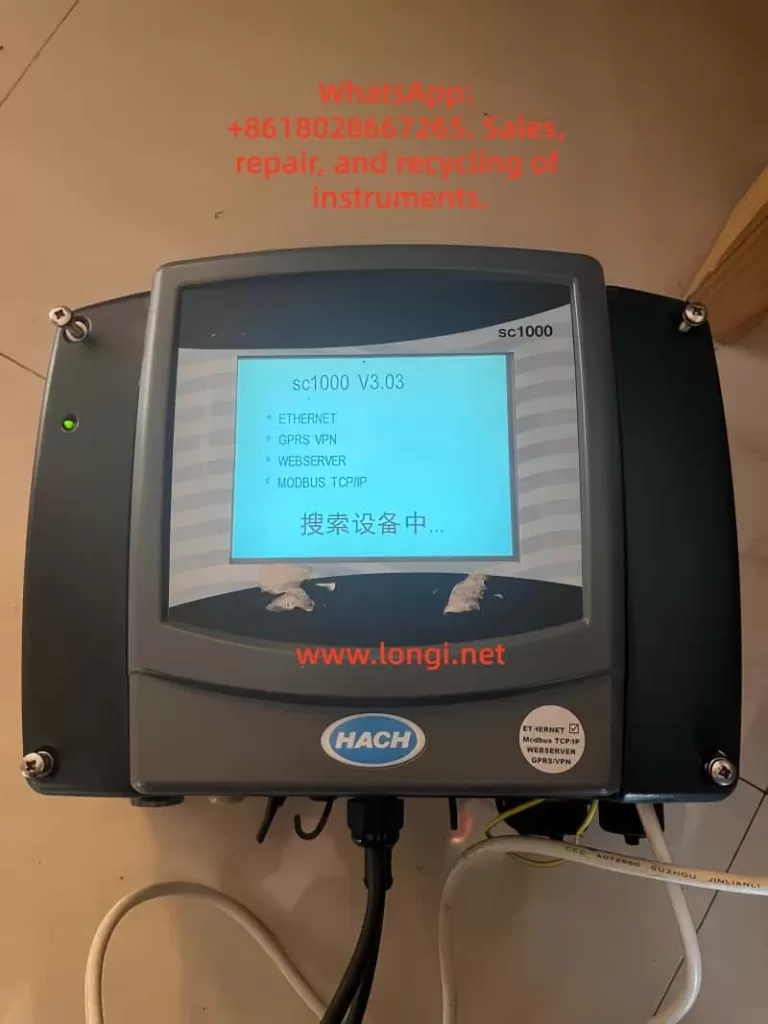
- Remote monitoring capability: Supports Ethernet and fieldbus modules for remote data access and system integration.
1.2 System Components
A standard SC1000 system typically consists of:
- Display module: Color display unit for real-time values, alarm status, and system configuration.
- Probe (controller) module: Core processing unit for sensor communication, data acquisition, and output control.
- Expansion cards: Including relay cards, analog input/output cards, and digital or fieldbus communication modules.
- Power and accessories: Power cables, fuses, mounting brackets, terminal blocks, and communication cables.
2. Installation Guide
2.1 Pre-installation Checklist
Before installation, verify the following:
- All components are complete and undamaged.
- The installation environment is dry, well ventilated, and free of strong electromagnetic interference.
- Adequate space is reserved for cable routing, ventilation, and maintenance access.
- Required tools are prepared (screwdrivers, drill, mounting hardware, cable glands, etc.).
2.2 Mechanical Installation
2.2.1 Dimensions and Space Requirements
- Display unit: approximately 200 × 230 × 50 mm
- Probe module: approximately 315 × 255 × 120 mm (excluding display)
- Clearance requirements:
- At least 5 cm clearance on sides and top for heat dissipation
- At least 15 cm clearance at the bottom for wiring
2.2.2 Wall-mount Installation
- Mark mounting hole positions on the wall according to the backplate.
- Drill holes and insert expansion anchors.
- Hang the controller on the mounting screws.
- Secure the bottom screws and verify the unit is firmly fixed.
2.2.3 Pipe or Panel Mounting
- Use the official HACH mounting kit.
- Install the brackets securely on horizontal or vertical pipes.
- Ensure vibration is minimized and cables are properly strain-relieved.
2.3 Electrical Installation
2.3.1 Power Supply Connection
The SC1000 supports both AC and DC power input:
- AC power: 100–240 VAC, 50/60 Hz
- DC power: 24 VDC (18–30 VDC range)
Installation procedure:
- Disconnect all power sources before wiring.
- Remove the probe module cover and safety barrier.
- Route the power cable through the sealed cable gland.
- Connect the power wires to the designated terminals.
- Reinstall the safety barrier and enclosure cover.
2.3.2 Expansion Card Wiring
Relay modules
- Disconnect power before installation.
- Remove the relay cover.
- Wire alarm or control loads according to the terminal diagram.
- Verify correct NO/NC selection and tighten all screws.
Analog / digital I/O cards
- Connect signal cables according to the card type (4–20 mA, digital input, digital output).
- Use shielded cables where possible.
- Ground shields at one end only to avoid ground loops.
2.4 Network and Sensor Connection
The SC1000 uses a digital network bus to connect probe modules and sensors.
Installation steps:
- Strip and prepare the network cable.
- Connect the wires to the communication terminal block.
- Secure the connector and install termination resistors if required.
- Insert the connector into the probe module network port.
- Power on the system and verify sensor recognition.
3. Operating Instructions
3.1 Display and Interface Operation
3.1.1 Touchscreen Calibration
Touchscreen calibration is recommended during initial commissioning or after display replacement.
Procedure:
- Enter System Settings → Display Settings → Touchscreen Calibration
- Follow on-screen instructions and confirm calibration points.
3.1.2 Menu Navigation
The main menu provides access to:
- Sensor status
- Measurement values
- Configuration and calibration
- Outputs and alarms
- System diagnostics
Navigation is performed using on-screen icons and soft keys.
3.2 Sensor Management
3.2.1 Sensor Status Monitoring
- View real-time measurements for each connected sensor.
- Check diagnostic messages, warnings, and error codes.
- Confirm communication and sensor health status.
3.2.2 Sensor Configuration
Within the sensor menu, users can configure:
- Measurement units
- Calibration parameters
- Alarm thresholds
- Output assignments
- Temperature compensation and filtering
Always follow sensor-specific manuals when performing calibration.
3.3 System Configuration
3.3.1 Output Settings
- Configure analog outputs (for example, 4–20 mA)
- Assign outputs to specific parameters
- Define scaling ranges, damping time, and failure behavior
3.3.2 Relay Settings
- Assign relays to alarms, setpoints, or system events
- Configure activation logic, delays, and hysteresis
- Test relay actions before commissioning
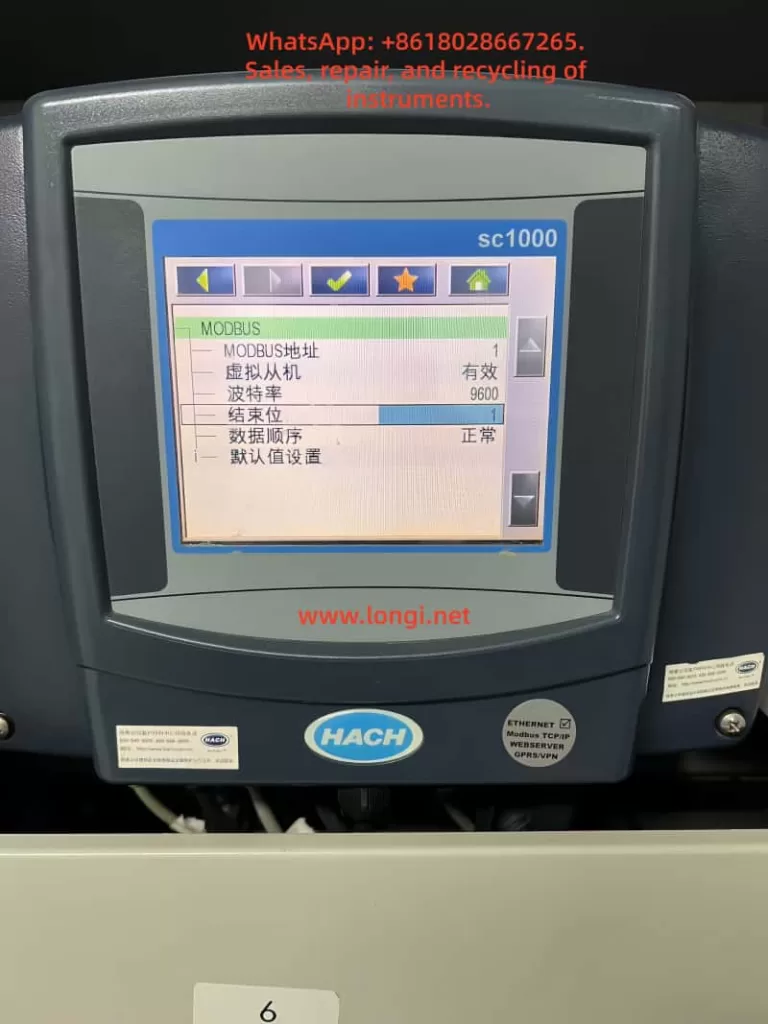
3.3.3 Communication and Network Settings
- Set Modbus address and baud rate
- Configure Ethernet or fieldbus parameters
- Verify data format consistency with PLC or SCADA systems
4. Maintenance and Troubleshooting
4.1 Routine Maintenance
- Inspect enclosures for dust, corrosion, or moisture ingress.
- Verify all terminals and connectors are secure.
- Clean the display and housing with a soft, damp cloth.
- Perform periodic sensor calibration according to application requirements.
4.2 Fuse Replacement
Before replacing fuses, disconnect all power sources.
Typical fuse types include slow-blow fuses such as M3.5A or T8A (refer to the nameplate).
Procedure:
- Remove the probe module cover.
- Take out the damaged fuse.
- Insert a fuse with identical rating.
- Reinstall covers and restore power.
4.3 Common Faults and Solutions
No display or no power
- Check power supply voltage.
- Inspect fuses and terminal connections.
Unstable or abnormal readings
- Check sensor wiring and connectors.
- Perform recalibration.
- Inspect sensors for fouling or damage.
Communication errors
- Verify address, baud rate, and protocol settings.
- Inspect network cables and termination.
- Check expansion cards and power stability.
5. Conclusion
The HACH SC1000 controller is a powerful and flexible water quality monitoring platform suitable for both industrial and municipal applications. With proper installation, configuration, and maintenance, the SC1000 provides reliable long-term performance and accurate multi-parameter measurement.
By following the procedures and best practices described in this guide, users can ensure stable system operation, accurate data acquisition, and efficient troubleshooting.