
I. Problem Background and Typical Phenomena
During on-site commissioning or maintenance of Siemens SINAMICS S120/S105 multi-axis and single-axis drive systems, the following issues frequently occur:
- The Control Unit (CU, such as CU310/CU320/CU_S_105) can be online normally.
- Performing a factory reset and configuration download on the CU alone proceeds normally, but when a Power Module (PM) is added, the download process gets stuck at 90% – 98%.
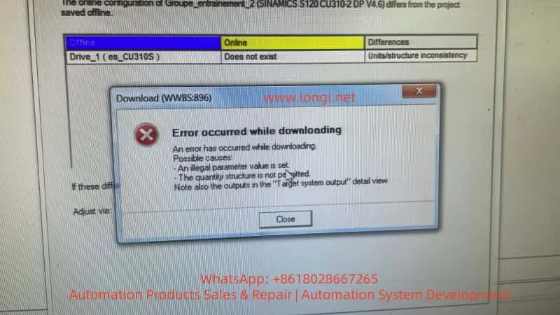
- STARTER/Startdrive reports errors, such as “Error occurred while downloading”, “Quantity structure is not permitted”, and “Units/structure inconsistency”.
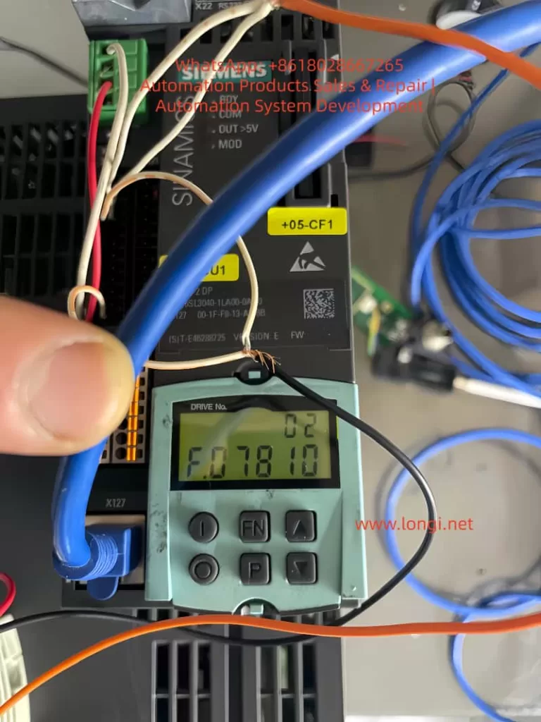
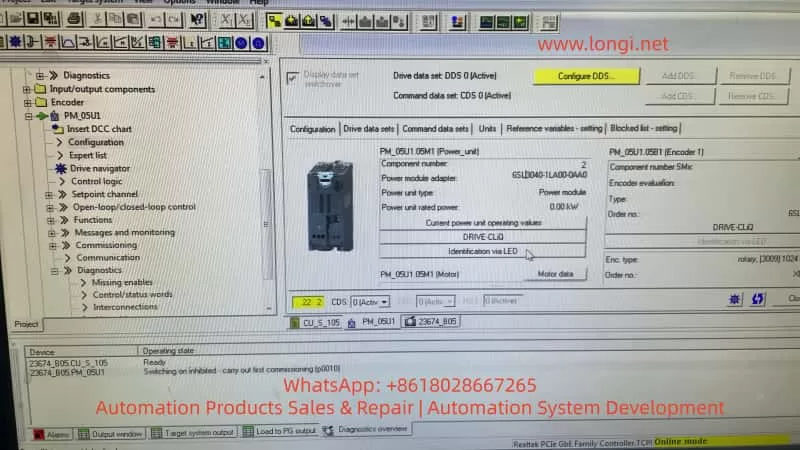
- In the parameter interface, the rated power of the PM is displayed as 0.00 kW, and almost all parameters are zero.
- In the Topology → Actual view, only the CU is visible, and no Power Module can be seen.
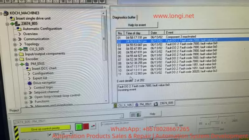
- Fault codes like Fault 7800, 1951/1651/30020 related to structure and synchronization repeatedly appear in the fault buffer.
Field engineers often repeatedly attempt operations such as factory resets, rebuilding projects, reinstalling software, repeated uploads/downloads, and changing project versions, but the phenomena remain unchanged. About 90% of such cases are misdiagnosed as “parameter problems” or “software problems”, when in fact they are hardware-level disconnection faults.
II. Understanding the Problem Essence from the System Architecture
SINAMICS S120/S105 is a distributed drive system, with its core composed of three types of units:
- CU (Control Unit): Responsible for computation, control, communication, and parameter management.
- PM (Power Module): Responsible for rectification, DC bus operation, inversion, and power output. It contains an independent control board, EEPROM, and communication interface.
- Motor modules/encoders/expansion modules
The CU and PM communicate via the DRIVE-CLiQ digital bus at high speed in real-time. When the system is normal, after the PM is powered on, its internal logic power supply starts, the nameplate data in the EEPROM is read, the PM “registers” on the bus, the CU scans the bus to establish the actual topology, reads the PM’s hardware information, and Starter allows parameter downloads based on the real hardware structure. “Topology recognition” is a prerequisite for all parameter configuration and downloads.
III. Why a “Download Stuck at 98%” is Almost Never a Software Problem
The general sequence of the SINAMICS download process is as follows: establishing online communication, verifying the CU, verifying the project structure, verifying topology consistency, writing CU parameters, writing PM parameters, writing drive data sets, synchronizing the structure, and completing the process. When “the CU can be downloaded normally, but the process gets stuck at 90 – 98% after adding the PM”, it indicates that communication, software, the CU, and the project files are normal, and the failure occurs during the stage of writing/synchronizing Power Module data. If, at the same time, no PM is visible in Topology → Actual and the PM rated power is 0.00 kW, it means the CU has not detected the Power Module at the physical layer, and the “download failure” is due to the system waiting for a non-existent hardware node.
IV. Key Criterion: Topology Structure is More Important than Fault Codes
In the SINAMICS system, the topology view is the most crucial factor for judging such problems.
- Normal state: In Topology → Actual, at least the CU and PM (with order number, serial number, and type) should be visible. Even if the PM parameters are lost or the EEPROM is abnormal, it will be displayed as an Unknown module or Faulty module.
- Current case: The topology scan is completed, and the log shows that uploading the actual topology is finished, but only the CU is present in the result, with no Power Module node. This is the strongest evidence indicating that at the DRIVE-CLiQ physical layer, the PM does not exist.
V. The True Meanings of Fault 7800/Structure Inconsistency/0 kW
These prompts are “result-type faults”:
- Fault 7800: Its essence is that there is a module in the project, but it is not present on the actual bus.
- Power unit rated power = 0.00 kW: The CU has not read any nameplate data from the PM, indicating that the EEPROM is not responding or the control board is not powered on, not that “parameters have not been written”, but that “the device does not exist”.
- Quantity structure not permitted: It means that the current actual system structure does not allow writing the project structure.
VI. Factors That Can Be Excluded
When the CU is online normally and the PM does not enter the topology, the following factors can be directly excluded:
- Software version issues
- Project file issues
- Parameter setting issues
- Incomplete factory resets
- Incorrect commissioning sequence
- User operation errors
VII. Definable Root Cause Ranges (Sorted by Probability)
When the PM does not enter the topology, there are only five types of root causes in engineering terms:
- Internal logic power supply damage of the PM (highest probability): The 24V → 5V/3.3V/1.2V power supply fails to oscillate, the control board is not powered on, the LED does not light up or behaves abnormally, and the PM physically exists but is “electronically dead”.
- Control board damage of the PM: The MCU does not start, the clock fails to oscillate, the reset circuit is abnormal, and the DRIVE-CLiQ chip does not work.
- Severe damage to the PM’s EEPROM/Flash: The program area is damaged, the nameplate area is unreadable, and the module cannot complete self-startup.
- Hardware damage to the DRIVE-CLiQ interface: The PHY chip is damaged, the isolator is damaged, the interface is damaged by ESD, and the CU cannot detect the node on the bus.
- Complete lack of auxiliary power supply for the PM: The internal auxiliary power supply is damaged, the control board has no power, which is equivalent to the module not being powered on.
VIII. Standard Engineering-level Diagnostic Path
When “download stuck at 98% + no PM in topology” occurs, the only correct diagnostic route is at the hardware layer.
- Step 1: Observe the PM’s status, check if there are any LEDs, whether there are any reactions when powered on, and whether there is initialization flashing.
- Step 2: Detect the PM’s control power supply. If maintenance conditions permit, measure the 24V on the PM’s control board and the DC/DC outputs (5V/3.3V/1.2V).
- Step 3: Rule out external communication problems by replacing the DRIVE-CLiQ cable and interface and conducting a separate CU ↔ PM connection test.
- Step 4: Perform cross-validation by connecting a known normal PM to this CU or connecting this PM to a known normal CU.
IX. Engineering Conclusions and Handling Strategies
After confirming that the PM does not enter the topology, the system engineering conclusion is a hardware-level fault of the Power Module. There are two technical routes:
- Board-level repair: Suitable for situations where there is electronic repair capability, power supply analysis capability, and chip-level maintenance conditions. Focus on checking the auxiliary power supply, EEPROM, control MCU, and DRIVE-CLiQ PHY.
- Module replacement: Suitable for on-site emergency repairs, situations without maintenance conditions, and when key equipment is shut down. Directly replace the PM with the same model, and the problem will disappear.
X. Common Misconceptions Among Engineering Personnel
| Misconception | Actual Situation |
|---|---|
| Constantly changing parameters | There is no device at the physical layer |
| Repeatedly performing factory resets | Ineffective for disconnected modules |
| Reinstalling Starter | Unrelated to hardware |
| Believing it is a “system malfunction” | Actually, it is PM electronic failure |
| Thinking the error prompt indicates “illegal parameters” | Actually, it means the structure does not exist |
XI. Final Conclusion
When in the SINAMICS system, the CU is normal, the PM download always fails, the PM parameters are zero, and no PM is present in the topology, it can be directly concluded that this is a hardware-level disconnection or failure fault of the Power Module, not a commissioning, software, or engineering problem, but a repair or replacement problem.
XII. Practical Value for Maintenance Companies
For maintenance-oriented companies, such cases are of great significance:
- They can be quickly (qualitatively determined) to avoid ineffective debugging.
- They can professionally persuade customers to enter the maintenance phase.
- They can serve as typical “PM control board damage” maintenance cases.
- They can help form a standard testing process.
- They can be used as a basis for quotation and technical explanations.
XIII. One-sentence Summary
In the SINAMICS system, as long as the Power Module does not enter the topology, all download and parameter problems are illusions. The real problem lies only in the hardware.