
Introduction: The Guardian of Thermal Management
In the landscape of industrial automation, the Allen-Bradley PowerFlex 400 AC drive is a staple for Fan & Pump applications, optimized for HVAC, water treatment, and building automation. In these critical environments, system stability is not just about energy efficiency—it is a cornerstone of operational safety.
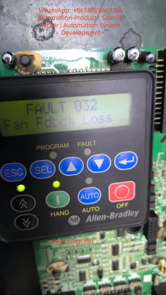
Among the various diagnostic codes, Fault 032 (F032) is one of the most significant yet misunderstood signals. It is more than a simple error; it is an urgent “SOS” from the drive’s thermal management system. This article provides a comprehensive analysis of the F032 fault, covering its underlying mechanisms, diagnostic logic, and a full-spectrum solution for maintenance engineers.
Chapter 1: Decoding F032 – The Critical Role of Fan Feedback
1.1 Defining the Fault
According to the PowerFlex 400 User Manual, F032 stands for “Fan Fdbck Loss.” This indicates that the drive has detected an inconsistency between the commanded state of the cooling fan and the actual speed feedback received by the control board.
This fault is specific to higher-power units, particularly those in Frame D and Frame E sizes. Unlike smaller drives that use simple “always-on” fans, these larger frames utilize a closed-loop monitoring system. The drive provides power to the fan and monitors a dedicated feedback line (usually a Hall-effect sensor signal) to verify rotation. If the drive expects the fan to spin but detects no pulses, it triggers an F032 trip to prevent the catastrophic failure of power components like IGBTs.
1.2 Why Only Large Frames?
Smaller units (Frame C) often rely on simpler cooling structures or auxiliary fans without feedback. However, Frames D and E integrate high-density power modules that generate significant heat. These frames require high-performance feedback-controlled fans to ensure cooling redundancy and safety.
Chapter 2: The Physical Logic of Thermal Management
2.1 The Enemy of Semiconductors: Heat
The core of the drive is the IGBT (Insulated Gate Bipolar Transistor). During high-speed switching, IGBTs generate substantial thermal energy through switching and conduction losses. If the heatsink’s heat is not extracted by the fan, the junction temperature rises rapidly. Exceeding the critical limit (typically 125°C–150°C) results in irreversible physical damage to the semiconductor structure.
2.2 Framework and Airflow Design
PowerFlex 400 is categorized by Frame Sizes to simplify maintenance.
- Frame D & E: These models feature powerful cooling fans located at the top or bottom. Their internal air ducts are designed for high-velocity vertical airflow, making the fan the single most critical component for hardware longevity.
Chapter 3: Multi-Dimensional Root Cause Analysis
When F032 appears, an engineer must use a “layered” diagnostic approach, moving from physical to electrical causes.
3.1 Physical Layer: Obstruction and Wear
- Mechanical Blockage: Cotton lint, dust buildup, or debris (like stray cable ties) can physically jam the fan blades.
- Bearing Failure: In high-temperature environments, bearing grease can dry out or carbonize, leading to increased friction, reduced speed, or a total seize-up of the motor.
3.2 Electrical Layer: Connections and Signals
- Loose Connectors: Constant micro-vibrations in industrial settings can cause the fan’s plug to drift from the control board socket.
- Feedback Circuit Failure: The internal Hall sensor within the fan may fail. In this case, the fan might physically spin, but the drive “sees” no speed pulses.
- Power Supply Issues: The Switched-Mode Power Supply (SMPS) providing 24V DC to the fan may experience voltage drops or failure.
3.3 Environmental Layer: Installation Layout
If the drive is installed in a space with insufficient clearance, backpressure increases. This forces the fan to work harder, potentially leading to speed fluctuations that trigger the feedback loss fault.

Chapter 4: Step-by-Step Diagnostic and Troubleshooting
Safety Warning: Before any disassembly, disconnect all power and wait at least 3 minutes for the bus capacitors to discharge to safe levels.
Step 1: Preliminary Visual and Manual Inspection
- Isolate Power: Lock out and tag out the input power.
- Access the Fan:
- Frame D: Loosen the two cover screws and pull the cover bottom out and up.
- Frame E: Loosen the four cover screws and pull the cover out and up.
- Manual Rotation: Spin the fan blades by hand. They should move freely. If you feel resistance or hear grinding, the fan must be replaced.
Step 2: Connection Integrity Check
- Locate the fan’s wiring harness connected to the main control board.
- Unplug the connector and inspect the pins for oxidation, corrosion, or burning.
- Reseat the connector firmly until it clicks into place.
Step 3: Voltage Measurement
- With the drive safely energized (following proper safety protocols), measure the DC voltage at the fan power terminals.
- A healthy PowerFlex 400 should provide a steady 24V DC.
- If 24V is present but the fan does not spin, the fan motor is defective.
Step 4: Pulse Signal Testing (Advanced)
Using an oscilloscope, you can probe the feedback line. A functional fan will produce a continuous square wave signal while spinning. A flat line (high or low) indicates a failed Hall sensor.
Chapter 5: Component Replacement and System Reset
5.1 Replacement Essentials
If the fan is confirmed faulty, it must be replaced with an identical OEM specification part. Pay close attention to airflow direction (usually indicated by an arrow on the fan housing). Installing the fan backward will cause heat to build up, leading to an immediate over-temperature trip.
5.2 Clearing the Fault
Once the hardware issue is resolved, reset the drive via:
- HIM Keypad: Press the Stop/Reset key.
- Power Cycle: Turn off the input power completely and restart.
- Parameter Reset: Set Parameter A197 [Fault Clear] to 1 or 2.
- Auto-Restart: If appropriate for your application, adjust A163 [Auto Rstrt Tries] and A164 [Auto Rstrt Delay].
Chapter 6: Preventative Maintenance Strategies
6.1 Environmental Optimization
- Dust Mitigation: Regular cleaning of the drive’s air intake is the best way to protect the fan.
- Ambient Control: Ensure the air temperature stays within the -10°C to 45°C range. In harsh environments, consider a NEMA 12 enclosure with filtered ventilation.
6.2 Lifecycle Management
Cooling fans are consumable parts. Following industry guidelines for solid-state controllers, it is recommended to proactively replace fans every 3 to 5 years, depending on the duty cycle and environment.
Conclusion
Fault 032 is a vital protective logic that ensures the longevity of your PowerFlex 400. By understanding the relationship between the physical rotation of the fan and the electronic feedback expected by the drive, engineers can move beyond “guessing” and implement precise, logical repairs. Regular maintenance and environmental awareness are the keys to ensuring your drive—and your facility—stays cool and operational.