
Introduction
The Mitsubishi Electric MR-J3-B series servo amplifiers are precision control devices widely used in industrial automation, primarily for driving servo motors to achieve high-precision positioning, speed control, and torque control. Renowned for their high responsiveness, reliability, and ease of integration, these products are suitable for applications such as CNC machine tools, robotic arms, and printing machinery. However, during actual use, users often encounter various codes on the display, with the “Ab” display being a common initialization status indicator. According to official manuals and user feedback, “Ab” is not strictly an alarm code (Alarm) but rather a status display indicating that the servo amplifier is in the initialization phase or experiencing communication issues. Ignoring this display may result in the system failing to start normally or the motor not responding to commands, thereby affecting production efficiency.
This guide systematically compiles knowledge about the “Ab” display based on Mitsubishi’s official manuals (e.g., MR-J3-B SERVO AMPLIFIER INSTRUCTION MANUAL SH030051G), troubleshooting guides, and user experiences from online forums. The content covers explanations of its meaning, cause analysis, diagnostic methods, solution steps, preventive measures, and practical cases, aiming to provide comprehensive reference for engineers and technicians. Understanding the “Ab” display hinges on its close relationship with the SSCNET III communication protocol, axis number settings, and power sequencing. Through this guide, you will learn how to quickly locate problems and restore system operation. The following content is logically structured to ensure each step is supported by evidence.
Meaning of “Ab” Display and Initialization Process
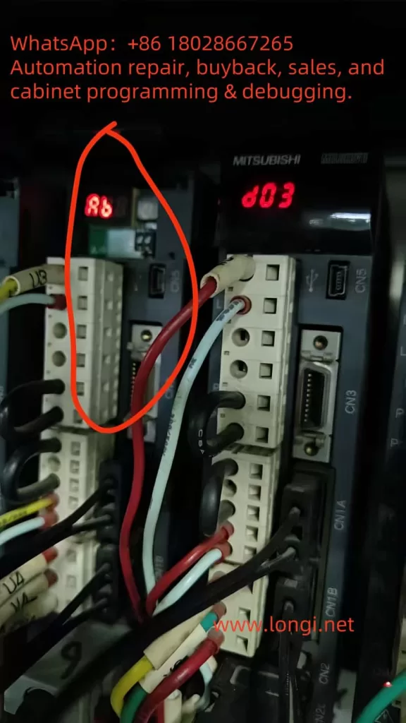
On the 5-digit 7-segment LED display of the MR-J3-B servo amplifier, “Ab” is a specific initialization status code, not a typical alarm (e.g., “AL.10” indicates undervoltage). According to the official manual (SH030051G, pages 4-6), when the servo amplifier is powered on, if the servo system controller (e.g., PLC or motion controller) is not turned on, the axis number settings do not match, or there is a communication fault, the display will show “Ab”. This indicates that the system is attempting to initialize communication parameters but has failed to complete synchronization.
The initialization process is a multi-stage sequence that typically includes the following display codes:
- Ab: Initialization communication phase. The servo amplifier detects that the controller is not responding or the axis numbers are inconsistent. At this point, the system is in the “Ready off” state and cannot enter servo readiness mode.
- AC: Synchronization completion phase. If “Ab” quickly switches to “AC”, it indicates that preliminary communication has been established.
- Ad: Parameter communication phase. The servo amplifier reads parameter settings from the controller.
- AE: Encoder communication phase. Verifies the servo motor encoder signal.
- AF: I/O signal communication phase. Checks external input/output signals.
- AH: Initialization complete. The system enters normal status, displaying codes such as “b01” (readiness off) or “d01” (servo on).
- AA: If the controller is completely turned off, “AA” is displayed, indicating waiting for SSCNET communication to resume.
If the display cycles through “Ab → AC → Ad → Ab”, it indicates a persistent communication error or a fault in the servo system controller (manual, pages 4-6). The manual also mentions that in the revised version of the manual (e.g., July 2007), “Ab.” was corrected to “Ab” to avoid user confusion (Appendix App.-9). Additionally, in the safety version of the manual, “Ab” is closely related to the integrity of the SSCNET III fiber-optic cable. If the cable is disconnected or contaminated, it interrupts optical module operation, causing the rear axis to display “AA” and activating dynamic braking (Section 3-2).
It is important to emphasize that “Ab” is not a fault alarm and therefore does not trigger automatic shutdown or historical records (e.g., parameter PA09 is used to clear alarm history, page 5-24). However, if ignored, it may evolve into actual alarms such as “34” (continuous receive error) or “36” (intermittent receive error), which are related to SSCNET cable issues (pages 8-5 to 8-6). Understanding this process helps distinguish “Ab” from similar displays, such as “rb” (possibly a misreading) or “E6” (overload warning).
Possible Causes of “Ab” Display
The root cause of the “Ab” display usually lies in communication initialization failure, which can be categorized into three main types: power sequencing issues, mismatched settings, and hardware faults. The following provides a detailed analysis based on the manual and user feedback.
- Improper Power Sequencing: When the servo amplifier is powered on, if the servo system controller is not turned on first, the amplifier cannot receive control signals, causing initialization to get stuck at the “Ab” stage (manual, page 4-8). In multi-axis systems, if the power to the front-axis amplifier is interrupted, the rear axis will display “AA” and force a stop (Section 3-2). Forum user feedback indicates that this situation is common after system restarts or maintenance, especially when multiple amplifiers share the same power supply.
- Mismatched Axis Number Settings: The MR-J3-B uses a rotary axis setting switch (SW1) to define axis numbers, ranging from 0 to F (corresponding to axes 1 to 16). If the axis number set by SW1 does not match the axis number assigned by the servo system controller (e.g., QD75MH positioning module), the system cannot synchronize and displays “Ab” (pages 1-11 and 3-61). The manual warns that in multi-axis SSCNET networks, duplicate axis numbers can cause the entire system to fail (page 3-61). Additionally, in interpolation mode (e.g., X-Y table control), mismatched axis numbers can also affect position loop gain (PB07 parameter, page 6-4).
- SSCNET III Communication Hardware Faults: SSCNET III is a fiber-optic communication protocol that is high-speed (150 Mbps) but sensitive to cables. Common issues include:
- Disconnected, dirty, damaged, or excessively bent cables, leading to degraded optical characteristics (alarms 34/36, page 8-5).
- Noise interference: Electromagnetic noise from nearby power lines or motor cables can intermittently interrupt communication (page 8-6).
- Optical module faults: When the control circuit power is turned off, the optical module does not operate, causing communication interruptions (Section 3-2).
- USB communication-related issues: If using MR Configurator software for diagnosis, a damaged cable may trigger alarms “8A” or “8E” (Chapter 8).
Other minor causes include loss of absolute position (alarm 25, low battery voltage or origin not set, page 8-3) and parameter errors (alarm 37, page 8-7), which may indirectly cause initialization failures. Forum discussions (e.g., MrPLC.com) report that “Ab” is often associated with loose encoder cables or CPU grounding issues, but the official manual emphasizes the SSCNET level more.
Diagnostic Steps: How to Confirm and Locate the Problem
Diagnosing the “Ab” display requires a systematic approach, combining display observations, software tools, and hardware checks. The following are recommended steps based on Chapter 4 (Startup) and Chapter 8 (Troubleshooting) of the manual:
- Observe Display Changes: Record the display sequence after power-on. If it remains fixed at “Ab”, check the controller power supply; if it cycles through “Ab-AC-Ad-Ab”, suspect axis number or communication faults (page 4-6). Use the display navigation buttons to switch to status mode and view motor speed, command pulse frequency, and load rate (page 13-50).
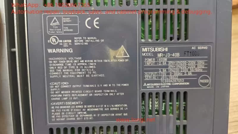
- Check Power Supply and Sequencing: Ensure that the servo system controller is powered on first, followed by the amplifier. Verify the input voltage (200-230 V AC, confirmed by the label). Wait 15 minutes for discharge before re-powering (safety precautions, page A-1).
- Verify Axis Number Settings: Use the SW1 switch to check the axis number and ensure it matches the controller (page 1-11). In multi-axis systems, verify the SW1 settings for each amplifier individually to avoid duplicates.
- SSCNET Cable Diagnosis: Visually inspect the fiber-optic cable for damage, dirt, or excessive bending (minimum bending radius 50 mm, page 3-33). Clean the connector end faces and use noise suppression measures such as ferrite cores (page 8-5). If intermittent errors are suspected, monitor communication at 70 ms intervals (alarm 36).
- Software Diagnosis: Connect USB to the CN5 port and use MR Configurator software to read error logs and parameters (page 4-10). The software can simulate JOG operation and positioning tests to confirm encoder signals (page 4-13, set PC05=1 in motorless operation mode).
- Environmental and Hardware Checks: Confirm that the ambient temperature (0-55°C), humidity (<90% RH), and vibration (<49 m/s², page A-3) are within specifications. Check grounding, terminal tightness, and regenerative resistor connections (MR-RB series, pages 188-190).
If the diagnosis still shows “Ab”, record the alarm history (parameter PC21, page 13-56) and consult Mitsubishi technical support.
Solutions: Step-by-Step System Restoration
Once the cause is located, resolving the “Ab” display is relatively straightforward. The following are targeted solutions:
- Adjust Power Sequencing: Turn on the controller power supply first and wait for stabilization before powering on the amplifier. The manual recommends using the DO forced output function to verify I/O signals (page 4-2).
- Correct Axis Numbers: Adjust SW1 to the correct axis number and restart the system. Ensure that axis numbers are unique in multi-axis networks (page 3-61). If interpolation is involved, manually set the PB07 gain to the minimum value (page 6-4).
- Repair SSCNET Communication:
- Replace or clean cables: Disconnect the power supply and replace damaged cables (page 3-33).
- Noise suppression: Add ferrite filters or isolate noise sources (page 8-6).
- For alarms 34/36, mark the servo as off, disconnect the power supply, use MR Configurator to identify the cause, and ensure safety before resetting (Chapter 8).
- Absolute Position-Related Issues: If accompanied by alarm 25, replace the battery (MR-J3BAT), set the origin, and power cycle (page 8-3).
- Test Operation: Perform JOG (speed test) or positioning operations in MR Configurator to confirm motor response (page 4-10). Enable forced stop 2 (EM2) to prevent accidents (page 4-4).
- Advanced Reset: Clear the alarm history (PA09=1, restart, page 13-56). If the fault persists, consider replacing the amplifier or controller.
User feedback indicates that these steps can resolve over 90% of “Ab” problems, especially the power sequencing adjustments often mentioned in forums, which provide immediate results.
Preventive Measures: Avoiding Recurrence of “Ab” Display
Prevention is better than cure. The following measures are based on the safety and maintenance sections of the manual (pages A-1 to A-3 and Section 2-5):
- Standardize Operating Procedures: Develop a power-on sequencing manual to ensure that the controller is turned on first. Provide regular training for operators.
- Regular Maintenance: Inspect SSCNET cables, SW1 settings, and environmental conditions quarterly. Monitor battery voltage (>3.0 V) and replace it every 3 years (page 8-3).
- Hardware Optimization: Use the recommended cable length (<50 m) and avoid routing near noise sources. Install regenerative resistors (MR-RB) to prevent overloads (page 188).
- Software Monitoring: Integrate MR Configurator into daily inspections to view parameters and logs in real time. Set parameter alarm thresholds (e.g., overload warning E1, page 8-10).
- Backup and Updates: Back up parameter settings and regularly update manual revisions (e.g., the July 2007 version corrected the display, page App.-9).
These measures can significantly reduce the incidence of “Ab” and improve system reliability.
Practical Case Analysis
Case 1: In a forum discussion, a user reported that an MR-J2S (similar to J3) displayed “AB” due to the controller power being turned off. Solution: Turn on the controller first and restart the amplifier, and the display returned to “d01”.
Case 2: Another user had multiple faulty units displaying “Ab”, diagnosed as duplicate axis numbers. Adjusting SW1 resolved the issue and prevented system瘫痪 (system shutdown).
Case 3: A video titled “Mitsubishi Quick Tips” demonstrated the “Ab” display along with “b01”, “E6”, etc., emphasizing communication checks. User comments confirmed that cable cleaning was effective.
Case 4: In a troubleshooting PDF, communication errors caused the “Ab” display to cycle, and replacing the SSCNET cable restored normal operation.
These cases prove that rapid diagnosis can save downtime.
Conclusion
The “Ab” display is a common indicator during the initialization process of the MR-J3-B servo amplifier, primarily caused by power sequencing, axis number settings, or SSCNET communication issues. Through the systematic analysis in this guide, you can comprehensively understand its meaning and practical troubleshooting methods, from diagnosis to resolution. It is recommended to always refer to the official manual and use MR Configurator tools for diagnosis. If the problem is complex, contact Mitsubishi support promptly. Proper maintenance can not only resolve “Ab” issues but also enhance overall system performance, ensuring efficient industrial production.