
Introduction
In the field of industrial automation, inverters are core devices for achieving motor speed regulation, energy-saving control, and closed-loop adjustment. The Sanjing Electric DPG10 series inverter, with its high cost-performance ratio and stable closed-loop control performance, is widely used in constant pressure/constant current control systems for loads such as centrifugal pumps, fans, and compressors. However, during long-term operation, the E024 “Feedback Line Break Fault” is one of the most common faults in the DPG10 series—minor faults cause equipment downtime, while major ones disrupt production continuity. This article combines the technical characteristics of the DPG10 series with on-site practical experience to provide a actionable full-process solution guide covering fault principles, cause analysis, troubleshooting steps, and preventive measures, helping engineers and technicians quickly locate and resolve issues.
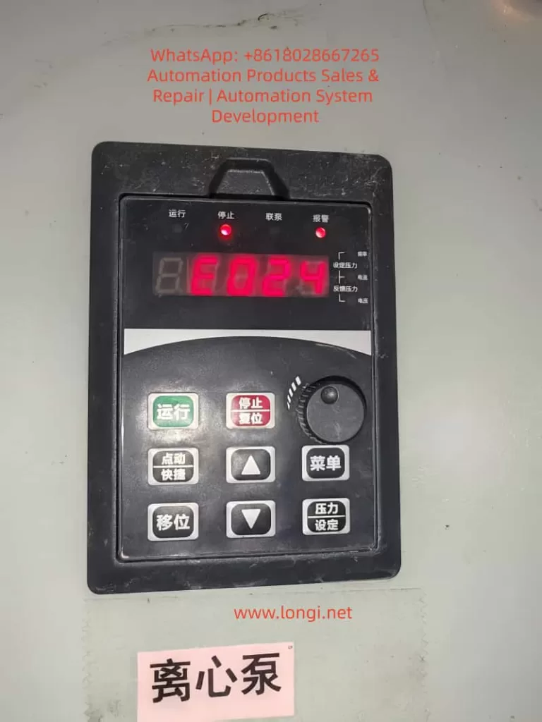
I. Core Principles and Trigger Mechanism of E024 Fault
The E024 fault in the DPG10 series inverter is essentially a protection mechanism for feedback signal abnormalities in closed-loop control mode. Its trigger logic is as follows:
When the inverter operates in closed-loop mode (e.g., pressure closed-loop, flow closed-loop), it real-time monitors the feedback signal (analog: 4-20mA/0-10V; pulse: encoder signal). If any of the following conditions is detected and lasts longer than the line break detection time (default: 1 second), the E024 fault is triggered:
- Complete interruption of the feedback signal (e.g., line break);
- Feedback signal value exceeds the reasonable range (e.g., pressure sensor outputs 0mA or >20mA);
- Feedback signal fluctuation exceeds the threshold (e.g., intermittent poor contact).
Review of Closed-Loop Control Process:
Set target value (e.g., pipeline pressure 0.5MPa) → Sensor collects actual value (converted to electrical signal) → Inverter compares target value with actual value via PID algorithm → Adjusts output frequency → Maintains actual value stability. If the feedback signal is abnormal, the PID algorithm fails to work, and the inverter stops output and alarms to protect the equipment.
II. Three Core Causes of E024 Fault
Based on statistics from over 100 on-site faults, the causes of E024 fault are distributed as: Line issues (60%) > Sensor issues (30%) > Parameter settings (10%). Detailed analysis is as follows:
(1) Line Issues: Break or Poor Contact (Most Common)
Lines are the “channel” for feedback signal transmission, and their faults mainly stem from physical damage or connection failure:
- Line break: External force damage (rat bites, construction misoperation), line aging (insulation layer cracking causing core wire breakage), or loose terminal screws (core wire detachment);
- Poor contact: Terminal oxidation (copper-aluminum connection produces oxide layer), loose plugs (aviation plugs not locked), or virtual connection of terminal blocks (screws not tightened).
Case: In a sewage treatment plant’s centrifugal pump system, moisture in the control cabinet caused oxidation of the pressure sensor terminals, resulting in intermittent feedback signals and frequent E024 faults in the inverter.
(2) Sensor Issues: Damage or No Output (Second Most Common)
Sensors are the “source” of feedback signals, and their faults directly lead to signal abnormalities:
- Sensor damage: Overload (pressure exceeding the range causes deformation of elastic elements), overvoltage (power supply voltage exceeding the rated value burns the circuit), or environmental factors (moisture short circuit, high-temperature aging);
- No feedback signal: Sensor not powered (power line break), range mismatch (e.g., sensor outputs 0-10V but the inverter is set to 4-20mA input), or installation error (pressure sensor not installed at the pressure tapping point).
Case: In a chemical plant’s fan system, the pressure sensor’s internal lead broke due to vibration, outputting 0V signal, and the inverter judged it as a line break.
(3) Parameter Settings: Too Short Detection Time or Incorrect Type (Rare)
- Too short line break detection time: The default 1-second detection time cannot adapt to system fluctuations (e.g., pressure shock during pump startup), causing false alarms;
- Incorrect feedback signal type: For example, if the sensor outputs 4-20mA but the inverter parameter is set to “pulse input”, the signal cannot be recognized.
Case: In a paper mill’s water pump system, the line break detection time was set to 1 second. During pump startup, pressure fluctuations lasted 1.5 seconds, and the inverter misjudged it as a line break. After adjusting the time to 3 seconds, the fault disappeared.
III. Full-Process Troubleshooting Steps for E024 Fault (Practical Guide)
Follow the principle of “hardware first, then software; simple first, then complex” and troubleshoot step by step:
Step 1: Check Feedback Lines (Priority, 60% of Causes)
Preparation: Disconnect the main power supply of the inverter (confirm power-off to avoid electric shock) and prepare a multimeter (continuity gear, voltage gear), screwdriver, and alcohol cotton.
- Check Terminal Connections:
Open the control cabinet, find the signal line between the sensor and the inverter (usually a shielded wire with white/blue core wires), and check if the terminals at both ends (e.g., inverter AI1/AI2, sensor output end) are loose or oxidized. If loose, tighten with a screwdriver; if oxidized, clean with alcohol cotton and reconnect. - Measure Line Continuity:
Use the multimeter’s continuity gear to measure both ends of the signal line (e.g., sensor output end → inverter AI1 end). If the multimeter does not beep (discontinuous), the line is broken and needs to be replaced with a shielded wire of the same specification (recommended RVVP2×1.0mm², with the shield layer grounded at one end only). - Check Shield Layer Grounding:
Ensure the shield layer of the shielded wire is grounded only at the inverter end (to avoid ground loops caused by dual-end grounding), and the grounding resistance is <4Ω (measured with a grounding resistance tester).
Step 2: Verify Sensor Validity (30% of Causes)
- Power-On Check for Sensor:
Use the multimeter’s voltage gear to measure the sensor’s power supply end (usually DC24V). If the voltage is 0V, check if the power line is broken or the power module is faulty. - Detect Sensor Output Signal:
- Analog Sensor (e.g., Pressure Sensor): Connect the multimeter in series (current gear) to measure the output current (4-20mA) or in parallel (voltage gear) to measure the output voltage (0-10V). If the output is 0mA/0V or exceeds the range, the sensor is damaged.
- Pulse Sensor (e.g., Encoder): Use an oscilloscope to measure the output pulse signal (e.g., for a 1000P/R encoder, the frequency is 16.67kHz at 1000rpm). If there is no pulse or the frequency fluctuates greatly, the encoder is damaged.
- Replacement Verification:
Replace with a spare sensor of the same model. If the fault disappears, the original sensor is damaged and needs to be replaced.
Step 3: Check Inverter Parameters (10% of Causes)
- Confirm Feedback Signal Type:
Enter the parameter mode (press the “Menu” key and enter the password), find the “Feedback Signal Selection” parameter (e.g., F0-03), and ensure the setting matches the sensor (set to “0” for 4-20mA, “1” for pulse). - Adjust Line Break Detection Time:
Find the “Line Break Detection Time” parameter (e.g., F8-01), change the default 1 second to 3-5 seconds (adjusted according to system fluctuations; recommended not to exceed 10 seconds), save the parameter (press “Shift + Menu” keys), and restart the inverter. - Verify Feedback Range:
Confirm that the “Feedback Range Upper Limit” (F8-02) and “Feedback Range Lower Limit” (F8-03) match the sensor’s range (e.g., for a 0-1.0MPa pressure sensor, set F8-02 to 1.0 and F8-03 to 0).
Step 4: Eliminate System Interference and Logic Issues (5% of Causes)
- Check Communication Logic:
If the inverter receives feedback signals via Modbus RTU, confirm that the register address, baud rate, and station number in the PLC program match the inverter (e.g., if the inverter’s station number is 1, the PLC must be set to 1). - Electromagnetic Interference (EMI) Protection:
- Route feedback lines separately in galvanized steel pipes and keep them away from power lines (≥30cm);
- Connect a 0.1μF/250V ceramic capacitor in parallel at the inverter’s feedback terminal (for filtering);
- Use a signal isolator (e.g., 4-20mA isolator) to cut off the interference path.
IV. Real Case Review: Practical Solutions for E024 Fault
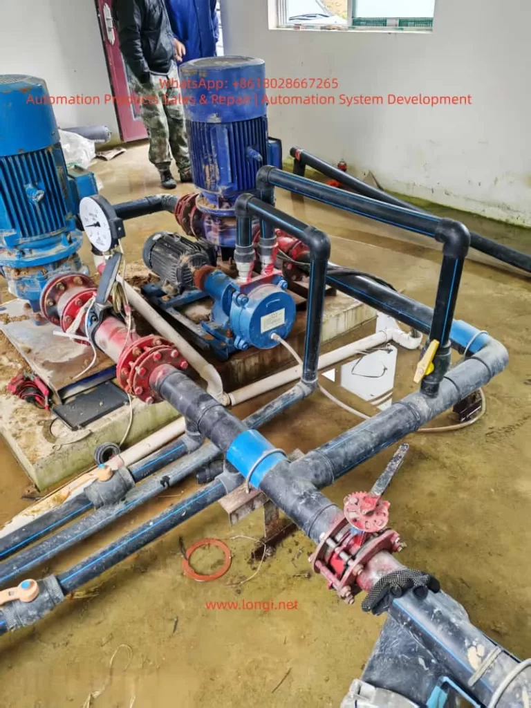
Case 1: Centrifugal Pump E024 Fault in a Sewage Treatment Plant
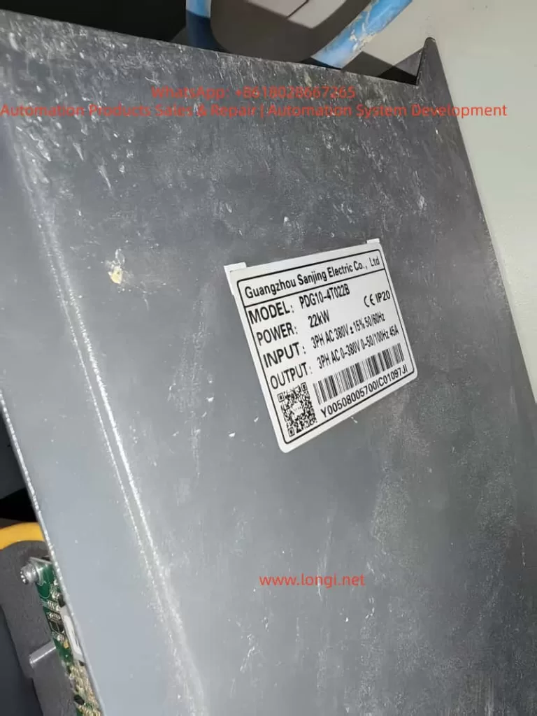
Fault Phenomenon: A DPG10-4T022B inverter (22kW) controlling a centrifugal pump suddenly reported E024 during operation, and the pump stopped with the alarm light on.
Troubleshooting Process:
- Disconnect power, check the pressure sensor (CYB-20S, 4-20mA) terminals, and find that the screw of the inverter’s AI1 terminal was loose, causing the core wire to detach;
- Tighten the terminal, clean the oxide layer, and use a multimeter to confirm the line was conductive;
- Power on and start the pump—pressure feedback showed 0.3MPa (normal), and the fault disappeared.
Cause: Loose terminal screws leading to poor contact.
Case 2: Fan E024 Fault in a Chemical Plant
Fault Phenomenon: A DPG10-4T030B inverter (30kW) controlling a fan reported E024 upon startup and could not enter closed-loop mode.
Troubleshooting Process:
- Check the line: The shielded wire was connected normally, and the continuity test passed;
- Detect the sensor: The pressure sensor (PT124B, 0-10V) had normal power supply but output 0V, indicating damage;
- Replace the sensor—feedback voltage was 5V (corresponding to 0.5MPa), and the fault disappeared.
Cause: Internal circuit damage of the sensor (vibration caused lead breakage).
Case 3: Water Pump E024 Fault in a Paper Mill
Fault Phenomenon: A DPG10-4T015B inverter (15kW) controlling a water pump frequently reported E024 and could only run for a few minutes after restarting.
Troubleshooting Process:
- Lines and sensors were normal, and the sensor output was stable (4-20mA);
- Check parameters: The line break detection time (F8-01) was set to 1 second. During pump startup, pressure fluctuations lasted 1.5 seconds, causing false alarms;
- Adjust F8-01 to 3 seconds, save, and restart—fault disappeared.
Cause: Too short line break detection time, unable to adapt to system fluctuations.
V. Preventive Measures for E024 Fault
- Regular Line Maintenance: Tighten terminal screws and clean oxide layers quarterly; replace aging shielded wires annually (recommended oil-resistant and corrosion-resistant types).
- Sensor Calibration and Replacement: Calibrate sensors with a standard signal source every six months; replace sensors after their service life (2-3 years).
- Rational Parameter Settings: Adjust the line break detection time (3-5 seconds) according to system fluctuations; ensure the feedback signal type and range match the sensor.
- EMI Protection: Route feedback lines in separate pipes and away from power lines; use shielded wires with one-end grounding; install signal filters.
- Fault Record and Analysis: Establish a fault log to record the time, phenomenon, and solution of each fault; analyze high-frequency causes (e.g., if line issues are common, strengthen line maintenance).
VI. Conclusion
The E024 fault in the Sanjing DPG10 series inverter is essentially a closed-loop control failure caused by feedback signal abnormalities. The key to solving it is accurately locating the fault point—troubleshoot step by step from lines (most common), sensors (second most common), to parameters (rare). On-site technicians need to be familiar with the inverter’s closed-loop principles, master methods for line inspection, sensor detection, and parameter adjustment, and accumulate experience through cases to quickly resolve issues.
Meanwhile, preventive measures such as regular maintenance, rational parameter settings, and EMI protection can effectively reduce the probability of E024 faults and ensure stable equipment operation. For unresolved faults, contact Sanjing Electric’s official after-sales service (provide inverter model, fault code, and working conditions) or use professional tools (oscilloscope, signal generator) for further diagnosis to avoid expanding losses due to misoperation.
Appendix: Reference Parameters for E024 Fault in DPG10 Series
| Parameter Code | Parameter Name | Default Value | Adjustment Suggestion |
|---|---|---|---|
| F0-03 | Feedback Signal Selection | 0 | Set to 0 for 4-20mA |
| F8-01 | Line Break Detection Time | 1 second | 3-5 seconds (adjusted by fluctuations) |
| F8-02 | Feedback Range Upper Limit | 100 | Match sensor range (e.g., 100 for 1.0MPa) |
| F8-03 | Feedback Range Lower Limit | 0 | Match sensor lower limit (e.g., 0 for 0MPa) |
(Note: Parameter codes are subject to the DPG10 series manual; different models may vary slightly.)
With this guide, engineers and technicians can quickly resolve E024 faults in the DPG10 series and improve equipment operation reliability.