
A System-Level Diagnostic Study Based on INCA micsF+
1. Introduction: Why Oxford INCA EDS Units Are Frequently Misdiagnosed as “Faulty”
Oxford Instruments’ INCA series Energy Dispersive Spectroscopy (EDS) systems are widely used in Scanning Electron Microscopes (SEM) and Electron Probe Micro-Analyzers (EPMA).
In real-world scenarios—such as relocation, resale, standalone testing, or board-level repair—engineers often encounter situations where an INCA unit appears to be malfunctioning:
- The unit does not enter a “ready” state
- LED indicators show red or yellow instead of green
- Two INCA units connected directly via IEEE-1394 behave inconsistently
- The unit remains in an apparent fault state when powered independently
These symptoms are very frequently misinterpreted as hardware failure, leading to:
- Unnecessary board-level repairs
- Incorrect valuation of expensive scientific instruments
- Disposal of fully functional systems
This article provides a system-level, engineering-based explanation of these phenomena using the INCA micsF+ as a representative example, focusing on FireWire power delivery, bus arbitration, startup logic, and LED status interpretation.

2. System Architecture: INCA Is Not a Standalone Instrument
2.1 Functional Role of the INCA Unit
A critical starting point:
Oxford INCA EDS units are not designed to operate as standalone instruments.
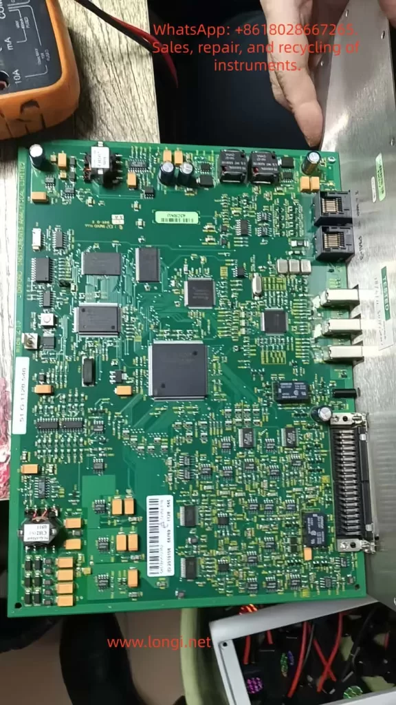
The INCA micsF+ is fundamentally:
- A front-end EDS electronic controller
- A high-speed data acquisition module
- A FireWire peripheral device
It relies on:
- A host computer equipped with an IEEE-1394 (FireWire) controller
- The INCA software environment
Without these, the unit cannot complete its operational initialization, regardless of power availability.
2.2 Common Misconceptions
Engineers unfamiliar with the INCA system often assume:
- “If it powers on, it should show green status.”
- “Two INCA units connected together should power and communicate.”
- “Yellow LED means a hardware fault.”
All of these assumptions are incorrect.
3. IEEE-1394 (FireWire): A Power-and-Control Bus, Not a Simple Cable
3.1 Key Characteristics of FireWire
IEEE-1394 differs fundamentally from USB or Ethernet in three major ways:
- Bus Power Capability
- 6-pin IEEE-1394a ports supply 8–30 V DC (typically ~12 V)
- External devices may be fully powered via the bus
- Mandatory Host / Bus Manager Role
- FireWire requires a bus master (host controller)
- Peripheral-only devices cannot arbitrate the bus independently
- Automatic Bus Initialization on Power-Up
- Bus Reset
- Node enumeration
- Role negotiation
FireWire is therefore a managed system bus, not a peer-to-peer network cable.
3.2 Why INCA Uses FireWire for Power
Oxford designed the INCA architecture such that:
- FireWire provides both communication and primary power
- Many INCA systems lack a dedicated external power supply
The standard topology is:
PC (FireWire Host)
        ↓ Power + Data
INCA EDS Unit
4. Incorrect Configuration: Why INCA-to-INCA Connection Fails
4.1 Typical Incorrect Setup
INCA Unit A ←── IEEE-1394 ──→ INCA Unit B
This configuration will almost always produce abnormal behavior.
4.2 Engineering Explanation
Both INCA units are:
- FireWire peripherals
- Not bus managers
- Not designed to supply stable bus power to another INCA unit
At startup, this leads to:
- Undefined power sourcing
- Failed bus arbitration
- Incomplete enumeration
As a result:
- One unit may show “ready” (green)
- The other remains in “fault” or “waiting” state (yellow)
This behavior is expected and does not indicate hardware damage.

5. LED Status Interpretation: The Most Critical Diagnostic Tool
5.1 Normal Startup Sequence
A correctly functioning INCA unit follows this LED sequence:
- Red LED flashing
- FPGA configuration
- Flash memory access
- Internal power rail initialization
- Red LED stops
- Power-on self-test (POST) completed
- Yellow LED steady
- Waiting for FireWire host enumeration
- Green LED
- Bus initialized
- Host communication established
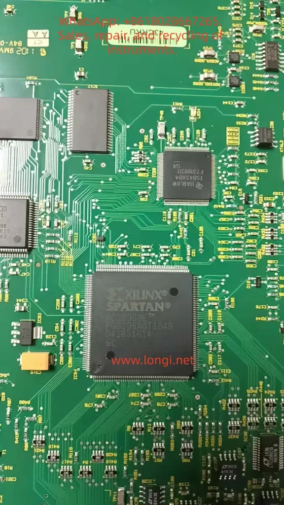
5.2 Meaning of Red LED Flashing
This is a crucial diagnostic indicator:
Red LED flashing confirms that the FPGA has been successfully configured.
Therefore:
- FPGA silicon is functional
- Configuration flash memory is intact
- Core power rails are operational
A truly failed FPGA typically results in:
- No LED activity
- Permanent red fault
- Complete inactivity
5.3 Yellow LED Does Not Indicate a Fault
In INCA systems, a steady yellow LED means:
The unit is powered and initialized, but no FireWire host is present.
This is the expected state when:
- The unit is powered independently
- No host PC is connected
- FireWire enumeration has not occurred
6. Standalone Power Testing: How to Interpret the Results Correctly
6.1 Acceptable Standalone Test Method
For engineering diagnostics, it is acceptable to:
- Supply ~12 V via the FireWire power pins
- Limit current to ~0.5 A
- Observe startup behavior
This test verifies:
- Power integrity
- FPGA boot sequence
6.2 Expected Results Without a Host
| Observation | Interpretation |
|---|---|
| Red LED flashes, then yellow | Normal |
| FPGA slightly warm | Normal |
| Current ~0.2–0.6 A | Normal |
| No green LED | Expected |
Green status cannot occur without a FireWire host.
7. When Should a Real Hardware Fault Be Suspected?
Only consider board-level repair when multiple abnormal conditions coexist, such as:
- No red LED activity at power-up
- Abnormally high or near-zero current
- FPGA remains completely cold
- No response even when connected to a known-good FireWire host
Absent these conditions, hardware failure is unlikely.
8. Correct System Validation Procedure
Recommended Test Topology
PC with PCIe FireWire Host
            ↓
       INCA EDS Unit
Validation Steps
- Install a reliable PCIe IEEE-1394 controller
- Use a 6-pin FireWire cable
- Connect a single INCA unit
- Power up
- Observe LED transition
- Check device enumeration in the OS
9. Engineering Conclusions
From systematic analysis, the following conclusions are definitive:
- INCA EDS units are not standalone devices
- FireWire provides both power and control
- INCA-to-INCA FireWire connection is invalid usage
- Red LED flashing confirms FPGA integrity
- Yellow LED without a host is normal
- True hardware faults are relatively rare
- Many “faulty” INCA units are fully functional
10. Final Remarks: System Understanding Prevents Costly Misdiagnosis
In high-value scientific instrumentation, misdiagnosis is often more expensive than actual hardware failure.
Oxford INCA systems are system-dependent by design.
Evaluating them without understanding FireWire bus behavior almost guarantees incorrect conclusions.
System knowledge, not guesswork, is the foundation of professional engineering diagnostics.