
1. Introduction
In the realm of industrial automation, the ABB ACS880 series of variable frequency drives (VFDs) stands as a benchmark for reliability, precision vector control, and advanced communication capabilities. Widely deployed in applications ranging from fans and pumps to conveyors and machine tools, these drives act as the “heart” of modern production lines. However, the stable operation of internal power components—specifically IGBT modules, rectifier bridges, and DC capacitors—relies heavily on an efficient thermal management system. At the core of this system lies the cooling fan, a component whose failure is statistically significant. According to ABB after-sales data, over 30% of VFD faults originate from thermal system anomalies, with Fault 5080 (Cooling Fan Stuck or Disconnected) being one of the most frequent early-warning faults in the ACS880 series.
If left unaddressed, this fault allows the internal temperature of the drive to rise unchecked. Once the IGBT junction temperature exceeds 150°C, it triggers a secondary over-temperature fault (Fault 5090), potentially leading to catastrophic component failure—such as IGBT explosions or capacitor bulging—resulting in costly unplanned downtime. This article provides a comprehensive technical analysis of Fault 5080, covering code interpretation, root cause analysis, systematic troubleshooting procedures, real-world case studies, and strategic preventive maintenance protocols.
2. Fault Code Analysis: Definition and Trigger Logic
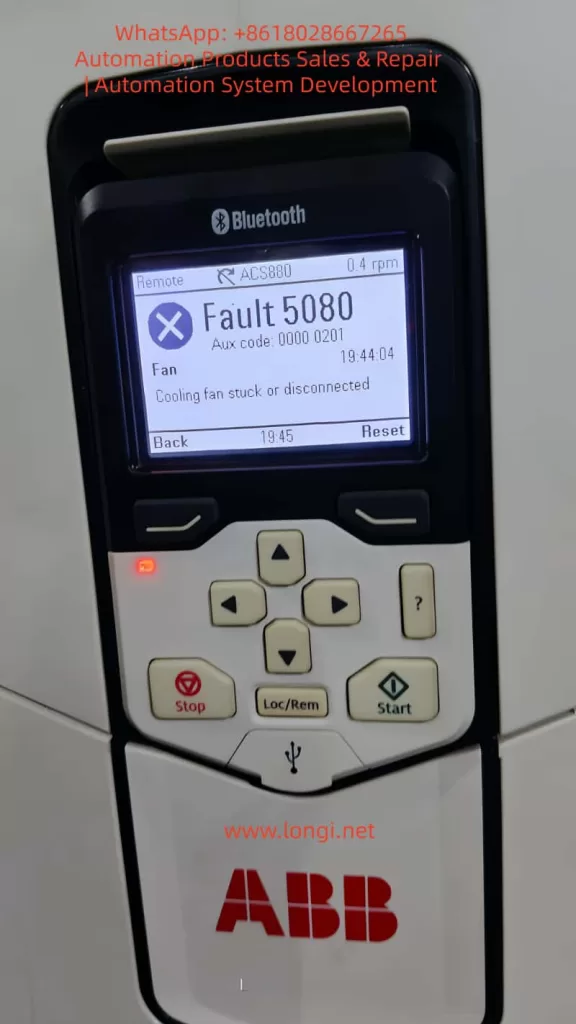
According to the official ABB ACS880 User Manual, Fault 5080 is defined as: Cooling fan stuck or disconnected. It falls under the “Fan” category, typically accompanied by an Auxiliary Code (Aux code) of 0000 0201 (though this may vary slightly depending on firmware version). The trigger logic is based on a closed-loop fan speed monitoring system:
- Sensing Mechanism: The drive utilizes an internal Hall effect sensor to monitor fan speed. This sensor outputs a pulse signal where the frequency is directly proportional to the rotational speed (e.g., 1500 rpm might correspond to a 25 Hz signal).
- Threshold Logic: The drive’s firmware continuously analyzes this signal. If the detected speed drops below 50% of the rated value (or if the signal is completely absent) for a duration exceeding 10 seconds, the fault is triggered.
- Protective Action: Upon triggering, the drive immediately inhibits output and trips to prevent thermal damage to the power semiconductors.
It is crucial to understand that Fault 5080 is a predictive warning. Its purpose is to alert maintenance personnel before the cooling system completely fails, thereby preventing the more severe consequences of over-temperature shutdowns or hardware destruction.
3. Root Cause Analysis: The Triad of Mechanical, Electrical, and Environmental Factors
The origins of Fault 5080 can be categorized into three primary domains: mechanical failure, electrical faults, and environmental degradation.
3.1 Mechanical Causes: Fan or Drive Mechanism Failure
Mechanical issues are the most prevalent, accounting for approximately 60% of cases:
- Bearing Wear/Seizure: Over time, lubricating grease in the fan bearings dries out or becomes contaminated with dust, increasing the friction coefficient. This causes a drop in RPM (e.g., from 1500 rpm to 800 rpm). In severe cases, the bearing seizes completely, stopping the fan.
- Dust/Debris Accumulation: In industrial environments, metal filings, fibers, and particulate matter accumulate on the fan blades or within the bearing assembly. This adds physical load, reducing rotational speed. Large debris (like screws or washers) can physically jam the blades.
- Blade Damage: Physical impact, material fatigue, or foreign object strikes can crack or break fan blades, destroying the dynamic balance. This leads to increased vibration and unstable speed readings.
3.2 Electrical Causes: Power or Signal Circuit Faults
Electrical anomalies represent the second major category (approx. 30%):
- Power Supply Failure: The fan’s DC power supply (typically 24V DC) may experience open circuits (broken wires, loose terminals), short circuits (damaged insulation), or voltage deviations (below 18V or above 30V). For instance, a terminal block screw loosening due to machine vibration can cut off power.
- Feedback Signal Failure: The signal lines connecting the Hall sensor to the mainboard (usually a 3-core cable: Power, Ground, Signal) may suffer from loose connections, electromagnetic interference (EMI) if routed parallel to power lines, or sensor failure. If the signal shield is compromised, high-frequency noise from the inverter output can corrupt the speed data, causing the mainboard to falsely interpret a stopped fan.
- Control Circuit Failure: Components on the mainboard responsible for fan control—such as relays, driver ICs, or operational amplifiers—may fail. A burnt-out relay contact, for example, will prevent power from reaching the fan even if the control logic is sound.
3.3 Environmental Causes: Deteriorating Operating Conditions
Environmental factors (approx. 10%) accelerate wear or increase thermal load:
- High Ambient Temperature: Operating in environments above 40°C increases the fan’s workload, accelerates grease evaporation, and degrades motor insulation.
- High Humidity: Relative humidity above 80% causes oxidation on terminals and rust in bearings, increasing contact resistance and mechanical drag.
- Poor Ventilation: If the drive cabinet is sealed too tightly or the cabinet exhaust fan is failing, heat recirculates inside. Even if the internal fan is spinning, it cannot dissipate heat effectively, potentially causing the drive to misinterpret the high internal temperature as a fan failure.
4. Systematic Troubleshooting: A Step-by-Step Guide
Resolving Fault 5080 requires a “Safety First, Outside-In, Mechanical-to-Electrical” approach.
4.1 Safety Preparation
- Lockout/Tagout (LOTO): Disconnect the main power supply (AC 380V/220V) and apply lockout devices.
- Discharge Wait: Wait at least 5 minutes for the DC bus capacitors to discharge (verify voltage is below 50V DC using a multimeter).
- PPE: Wear insulated gloves and safety glasses. Use ESD-safe tools to prevent static damage to sensitive electronics.
4.2 Visual Inspection
Open the drive cover and inspect:
- Fan Condition: Check for cracked blades, clogged protective grilles, or deformed housings.
- Wiring: Look for loose wires, burnt insulation, or oxidized (green/white crust) terminal blocks.
- Internal Cleanliness: Assess the level of dust accumulation on the fan, heatsinks, and IGBT modules.
4.3 Mechanical Verification
- Disconnect the fan power connector.
- Manually rotate the fan blades.
- If Stiff/Jammed: Clean dust/debris from blades and bearings. If the bearing makes grinding noises or has significant play, replace the fan assembly.
- If Smooth: Proceed to electrical diagnostics.
4.4 Electrical Diagnostics
4.4.1 Power Supply Measurement
- Re-energize the main power (do not start the motor yet).
- Use a multimeter (DC Voltage mode) to measure the voltage across the fan connector (Red to Black wires).
- Normal: 22V–26V DC.
- Abnormal (e.g., 15V): Check for broken conductors (use continuity mode; resistance should be ~0Ω) or loose terminals. If wiring is intact, the internal power supply module may be faulty.
4.4.2 Feedback Signal Analysis
- If voltage is normal but the fault persists, use an oscilloscope to measure the signal line (Yellow to Black).
- Normal: A stable frequency pulse train (e.g., 25Hz for 1500rpm).
- No Signal: Indicates a failed Hall sensor (replace fan).
- Noisy/Erratic Signal: Indicates EMI. Re-route signal cables away from motor power cables (minimum 10cm separation) and ensure the shield is properly grounded.
4.5 Control Circuit Inspection
If power and signals are verified but the fan does not spin:
- Locate the fan control relay on the mainboard. Measure the coil voltage.
- Voltage Present, No Click: Replace the relay.
- No Voltage Output: The driver IC or microcontroller may be damaged. This usually requires board-level repair or replacement by a certified technician.
4.6 Reset and Verification
- Press the 【Reset】 button on the control panel.
- Start the drive and monitor the fan speed via the Drive Composer software or the panel display. It should stabilize at 90–110% of the rated speed.
- Run the drive under load for 30 minutes, monitoring the IGBT temperature (should remain below 80°C).
5. Case Studies: From Symptom to Resolution
Case 1: Intermittent Fault Due to Loose Terminal
Scenario: An ACS880-01-05A3-2 driving a blower fan in a steel plant trips with Fault 5080 every 2–3 hours.
Investigation: Visual inspection revealed minor dust on the fan guard. Manual rotation was smooth. Voltage measurement at the fan plug showed only 15V DC (nominal 24V).
Root Cause: The red (+24V) wire at the terminal block had loosened due to machine vibration, creating high contact resistance.
Solution: Power down, retighten the terminal screw, and secure the wire with insulation tape.
Result: The drive ran for 8 hours without tripping. Fan speed stabilized at 1450 rpm, and internal temperature remained at 65°C.
Case 2: Bearing Wear Causing Speed Drop
Scenario: An ACS880-01-12A3-2 driving a water pump trips with Fault 5080. The panel indicated a speed of 800 rpm (rated 1500 rpm).
Investigation: The fan was dusty. Manual rotation produced a grinding noise and significant resistance. Disassembly revealed the bearing grease had completely liquefied and leaked out, with visible pitting on the ball bearings.
Solution: Replaced the fan with an ABB genuine part (Model 3BSE023456R1).
Result: Speed returned to 1480 rpm. The drive operated for 24 hours without alarms, with a cabinet temperature of 55°C.
Case 3: Electromagnetic Interference (EMI) False Trigger
Scenario: An ACS880-01-20A3-2 driving a conveyor belt trips with Fault 5080 immediately upon start, despite the fan visibly spinning.
Investigation: Voltage supply was steady at 24V. However, an oscilloscope connected to the signal line showed a chaotic waveform filled with high-frequency noise (100Hz+), rather than a clean square wave.
Root Cause: The fan signal cable was routed parallel to the motor power cable (AC 380V) with only 5cm separation, inducing noise.
Solution: Separated the signal cable from the power cable by 20cm and wrapped the signal cable in aluminum foil shielding, grounding the foil at the drive end.
Result: The fault cleared. The signal waveform normalized to a clean 25Hz pulse, and the drive ran trouble-free for a week.
6. Preventive Maintenance Strategy: Shifting to Predictive Maintenance
Preventing Fault 5080 requires a strategy that moves beyond “run-to-failure” toward a structured maintenance lifecycle.
6.1 Scheduled Maintenance Plan
| Frequency | Action Items |
|---|---|
| Monthly | Visually inspect fan rotation (manual check); clean dust from fan guards. |
| Quarterly | Remove fan; clean blades and bearing housing; apply high-temperature grease (e.g., Kluber PETAMO GY 193). |
| Semi-Annually | Check terminal tightness; measure fan supply voltage (tolerance ±10% of 24V). |
| Annually | Replace cooling fans (preventative replacement is cheaper than downtime). |
| Bi-Annually | Perform “Blow-out”: Use compressed air (<0.2 MPa) to clean internal dust from heatsinks and PCBs. |
6.2 Environmental Optimization
- Thermal Management: Ensure ambient temperature stays below 40°C. Install auxiliary cabinet cooling units if necessary.
- Humidity Control: Maintain relative humidity below 80%. Use dehumidifiers in damp environments.
- Cabling Standards: Strictly segregate high-voltage power lines from low-voltage signal lines (minimum 10cm spacing). Use shielded cables for all sensor connections.
6.3 Condition Monitoring (IoT)
Leverage ABB Ability™ Smart Sensor or similar IIoT gateways to monitor:
- Vibration: Set alarms for vibration levels exceeding 0.5mm/s (indicative of bearing wear).
- Temperature: Monitor IGBT heatsink temperature; set a pre-alarm at 90°C to trigger a fan check before a trip occurs.
- Speed: Configure the system to send an email/SMS alert if fan speed drops below 80% of nominal.
7. Conclusion
Fault 5080 on the ABB ACS880 is a critical indicator of thermal system health. While often caused by simple issues like loose wires or dust accumulation, it can also signal complex electrical failures or environmental stress. By adhering to a systematic troubleshooting methodology—prioritizing safety, visual inspection, and step-by-step electrical verification—maintenance teams can resolve these issues efficiently.
However, the true value lies in prevention. Implementing a rigorous schedule of cleaning, component replacement, and environmental control, augmented by modern condition monitoring tools, can reduce fan-related failures by over 80%. This proactive approach not only extends the lifespan of the VFD but also safeguards the continuity of industrial processes, turning maintenance from a cost center into a strategic asset.
For complex board-level failures or persistent intermittent faults that defy standard diagnostics, engaging ABB certified service partners is recommended to ensure the integrity of the drive system.