
Introduction
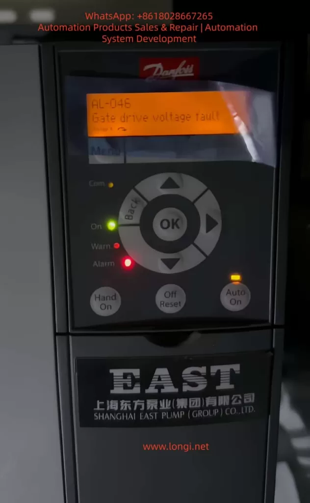
Danfoss Variable Frequency Drives (VFDs) are widely used in industrial automation for their efficiency and reliability. However, prolonged operation or adverse environmental conditions may lead to faults, with AL-046 (Gate Drive Voltage Fault) being a critical hardware issue. This fault involves the interplay of drive circuitry, IGBT modules, and control logic, requiring systematic troubleshooting to prevent equipment downtime or secondary damage.
This guide provides a comprehensive analysis of AL-046 fault mechanisms, step-by-step repair procedures, real-world case studies, and preventive strategies to assist technicians in resolving this complex issue.
Chapter 1: Fault Mechanism Analysis
1.1 Role of Gate Drive Voltage
IGBTs (Insulated Gate Bipolar Transistors) are pivotal for power conversion in VFDs. Their switching behavior is controlled by the voltage applied between the gate (G) and emitter (E). Danfoss VFDs utilize drive circuitry to convert PWM signals from the control board into appropriate gate voltages (typically +15V/-8V), ensuring efficient IGBT operation.
Core Issue of AL-046: Abnormal gate voltage (overvoltage, undervoltage, or complete loss) disrupts IGBT switching, triggering protective shutdowns.
1.2 Fault Detection Logic
- Hardware Monitoring: Drive boards integrate voltage-sensing circuits to feedback real-time gate voltage to the control board.
- Software Protection: If abnormalities persist beyond a threshold (e.g., 200ms), the control board reports AL-046 and halts operation.
1.3 Common Causes
| Category | Root Causes | Impact Analysis |
|---|---|---|
| Drive Circuit Issues | Power supply failure, optocoupler degradation, capacitor aging | Unstable/no voltage output |
| IGBT Anomalies | Gate-emitter short circuit, internal module breakdown | Voltage collapse or short circuit |
| Control Board Faults | Abnormal PWM signals, communication loss | No valid input to drive circuits |
| External Interference | Power fluctuations, EMI | Signal noise causing voltage instability |
Chapter 2: Repair Tools & Safety Protocols
2.1 Essential Tools
- Safety Gear: High-voltage gloves, discharge rods, multimeters (CAT III 1000V+).
- Precision Instruments: Oscilloscopes (≥100MHz bandwidth), insulation testers, IGBT testers.
- Auxiliary Tools: ESD wrist straps, soldering stations, component kits.
2.2 Safety Guidelines
- Power-Down & Discharge: Cut off power and wait 15 minutes; verify bus voltage <36V DC using a multimeter.
- ESD Protection: Wear wrist straps and avoid direct contact with IGBT gates.
- Component Replacement: Use OEM or certified parts; document specifications (e.g., capacitance, IGBT model).
Chapter 3: Systematic Repair Workflow
3.1 Preliminary Diagnosis
- Visual Inspection: Check for burns, corrosion, or loose connectors on drive boards/IGBTs.
- Power Quality Check: Ensure input voltage balance (±10% tolerance).
3.2 Drive Board Troubleshooting
3.2.1 Power Supply Test
- Test Points: Drive board input terminals (+24V/+15V).
- Criteria: Voltage stability within ±5% of nominal value; no AC ripple.
- Action: Repair switching power supplies or replace capacitors if anomalies exist.
3.2.2 Optocoupler & Signal Path Test
- Optocoupler Check: Measure input/output resistance (open-circuit unpowered, low-resistance when energized).
- Signal Tracing: Use oscilloscopes to validate PWM integrity (amplitude, frequency, dead-time).
3.2.3 Capacitor Health Assessment
- Electrolytic Capacitors: Measure capacitance and ESR; replace if capacitance drops >20% or ESR doubles.
3.3 IGBT Module Testing
3.3.1 Static Test (Offline)
- Gate-Emitter Resistance: Normal = open circuit (OL on multimeter); short indicates IGBT failure.
- Collector-Emitter Leakage: Insulation test >100MΩ.
3.3.2 Dynamic Test (Online/Offline)
- Double-Pulse Test: Inject signals to evaluate switching characteristics (Miller plateau voltage, turn-off spikes).
- Waveform Analysis: Normal gate voltage should be noise-free with correct amplitudes (+15V/-8V).
3.4 Control Board Verification
- PWM Signal Validation: Confirm amplitude (3–5Vpp) and frequency match specifications.
- Communication Check: Inspect optical/cable links between control and drive boards.
3.5 System Validation
- Load Testing: Gradually increase load while monitoring voltage, IGBT temperature, and output current.
- Long-Term Operation: Run for 2–4 hours to confirm fault resolution.
Chapter 4: Case Study
4.1 Scenario
A Danfoss VLT® AutomationDrive FC 302 reported intermittent AL-046 faults.
4.2 Diagnosis
- Initial Findings: Bulging capacitor (C12) on drive board; voltage dropped to +12V (nominal +15V).
- Advanced Testing:
- Optocoupler (TLP350) input degradation caused signal delay.
- Dynamic IGBT test revealed turn-off spikes up to +22V (safe limit: ≤+18V).
4.3 Solution
- Replaced C12 and optocoupler.
- Optimized gate resistance and added TVS diodes to suppress spikes.
- Installed OEM IGBT module.
4.4 Result
Stable operation with voltage fluctuations <±2%; fault resolved.
Chapter 5: Preventive Strategies
5.1 Environmental Optimization
- Temperature Control: Maintain ambient temperature ≤40°C with fans/AC.
- Dust/Moisture Management: Regularly clean filters; use dehumidifiers in high-humidity areas.
5.2 Maintenance Schedule
| Frequency | Tasks |
|---|---|
| Monthly | Check cooling fans, clear dust |
| Quarterly | Measure power quality, test capacitors |
| Annually | Full functional test, backup parameters |
5.3 Load Management
- Avoid prolonged overloading (≤90% rated capacity).
- Equip regenerative loads (e.g., cranes) with brake units.
Conclusion
Resolving AL-046 faults demands a blend of theoretical knowledge, precision tooling, and methodical troubleshooting. By adhering to systematic diagnostics and preventive measures, technicians can enhance VFD reliability and extend service life. Always prioritize safety and documentation to streamline future maintenance.
This guide provides a rigorous framework for addressing AL-046 faults while emphasizing best practices in industrial electronics repair.