
I. Instrument Overview and Safety Precautions
1.1 Product Introduction
The Thermo Fisher Orion 3106 Chemical Oxygen Demand (COD) Online Automatic Monitor is a high-precision analytical device specifically designed for water quality monitoring. It is widely used in定点 (fixed-point) water quality monitoring at key pollution source wastewater discharge points and in water quality monitoring at the outlets of sewage treatment plants. This instrument employs a 450nm colorimetric testing principle, with a measurement range of 20 – 2000 mg/L COD and a minimum detection limit of 4 mg/L. The indication error is ±10% (tested with potassium hydrogen phthalate), meeting the stringent requirements of various water quality monitoring applications.
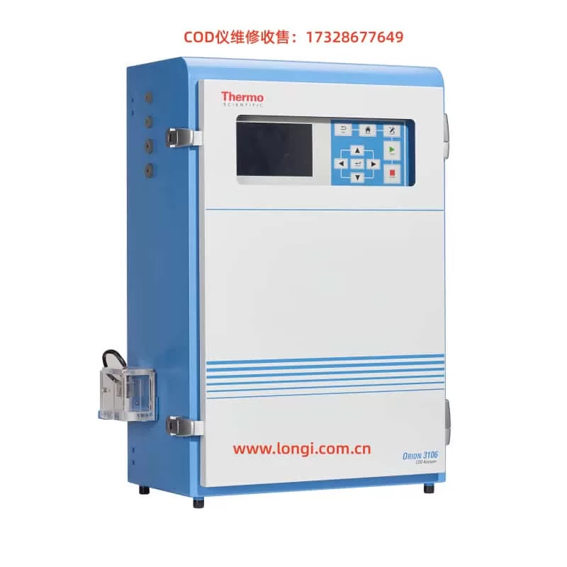
The instrument consists of two main parts: an electrical control system and a water sample analysis system. The electrical control system includes a power module, a circuit control system, and a user interaction panel, featuring functions such as power-on self-test and fault alarm. The water sample analysis system encompasses functions for water sample and reagent intake, water sample digestion, and measurement analysis. It utilizes syringe pumps for high-precision intake and implements precise temperature control to ensure complete and thorough digestion.
1.2 Safety Precautions
Before using the Orion 3106 COD Monitor, the following safety regulations must be strictly adhered to:
Electrical Safety:
- Disconnect the power supply before performing maintenance or internal wiring on the instrument.
- Do not operate the instrument with the safety panel or electrical cabinet door open.
- All electrical connections must comply with local or national safety regulations.
Chemical Safety:
- Wear protective gear (lab coat, protective goggles/face shield, protective gloves) before replacing reagents.
- Work only in areas equipped with exhaust ventilation.
- Use only glass or Teflon materials when handling chemicals.
- Dispose of waste liquids (containing heavy metal ions such as silver, mercury, and chromium) in accordance with local regulations.
Operational Environment Safety:
- Do not use the instrument in environments not specified in this manual.
- Do not open the safety panels inside the equipment during operation.
- Never use deionized water, drinking water, or beverages as a substitute for reagents to prevent explosion of the digestion tube.
Special Warnings:
- The instrument may contain overheated components (up to 175°C) and high-pressure areas.
- Various safety labels (electric shock warning, grounding warning, overheating warning, etc.) are affixed to the instrument. Carefully identify them before operation.
II. Instrument Installation and Initial Setup
2.1 Pre-installation Preparation
Unpacking Inspection:
- Check the outer packaging for any visible damage. If found, report it to the shipping company.
- Verify the product and accessories against the packing list. Immediately contact the Thermo Fisher representative office if any items are missing or damaged.
Installation Environment Requirements:
- Operating temperature: 5°C to 40°C (recommended 20 ± 10°C).
- Maximum humidity: 90% RH (recommended non-condensing).
- Can be installed outdoors (IP66 protection rating), but avoid direct sunlight and ensure the diurnal temperature variation does not exceed ±10°C.
- Install as close as possible to the sample source to minimize water sample analysis delay.
- Avoid environments with irritating or corrosive gases.
2.2 Instrument Installation Steps
Installation Method Selection:
- Wall mounting: Ensure the wall can withstand at least four times the weight of the instrument (approximately 40 kg).
- Bracket mounting: Use the four M8 base screws provided with the instrument for fixation.
Space Requirements:
- Reserve at least 700 mm of space on the right side for easy door opening.
- Reserve sufficient space on the left side for piping and wiring.
- The installation height should align the screen with the operator’s line of sight.
- Ensure the instrument is level after installation (recommended to use a spirit level for adjustment).
Flow Cell Installation:
- The flow cell must be installed in the lower left position of the instrument.
- The installation position should be higher than the water level of the sampling pool.
- Ensure the sampling tube is inserted into the flow cell and below the overflow level.
- A 200-micron stainless steel filter screen must be installed and cleaned regularly.
Electrical Connection:
- Power requirements: 100–240 VAC, 110 W, 50/60Hz.
- Use a three-core power cord (minimum 0.75 mm²/18AWG) with a temperature resistance of ≥75°C.
- It is recommended to install an external power switch or circuit breaker box (with leakage protection).
2.3 Tubing Connection and Reagent Preparation
Reagent System:
- Prepare two types of reagents (Reagent 1 and Reagent 2) and 1 – 2 types of standard solutions.
- Reagent bottle capacities: Reagent 1 (1000 mL), Reagent 2 (2000 mL), standard solution bottle (250 mL).
- The tubing must be correctly inserted into the bottom of the corresponding reagent bottles, and ensure all bottle vents are unobstructed.
Waste Liquid System:
- The waste liquid bucket should be no less than 25 L and placed below the instrument.
- Three waste liquid tubes should be uniformly inserted into a single PVC main waste liquid tube with an inner diameter of 12 mm.
- The waste liquid tubes should not be immersed in the waste liquid level to prevent back-suction.
- Waste liquids should be treated as hazardous waste.
Deionized Water System:
- The deionized water bucket should be no less than 18 L.
- Water quality requirements: colorless and clear liquid with a resistivity > 0.5 MΩ·cm.
III. System Startup and Basic Operation
3.1 Initial Startup Procedure
Pre-power-on Inspection:
- Confirm that the safety panel is installed.
- Check that all tubing connections are correct.
- Verify that reagents and deionized water are adequately prepared.
System Initialization:
- After powering on, the instrument enters the initialization selection interface.
- If the previous analysis process was forcibly stopped, it is recommended to select “Yes” to run initialization.
- The “Auto Initialization” option in system management can be set to automatically complete this process.
Flow Path Priming:
- Navigate to the menu: “Instrument Maintenance” > “Prime Solution” > “Prime All Tubing.”
- The purpose is to expel air from the tubing and ensure normal subsequent analysis.
3.2 Operation Interface Explanation
Main Interface Display:
- The most recent two measurement results (COD concentration values and measurement times).
- The current status display area of the instrument.
- The error or warning message display area.
Keyboard Function Definitions:
- 【MENU】: Main interface key for quickly returning to the analysis results interface or the first-level menu.
- 【RUN】: Run key for manually starting a test.
- 【STOP】: Stop key for stopping the current test during operation.
- 【ENTER】: Confirm key for parameter configuration or menu selection confirmation.
- 【ESC】: Cancel operation key for returning to the previous menu.
- Direction keys: For option movement or historical data page turning.
- 【FUNC】: Function key for switching between large font/normal font display.
3.3 Menu Structure Overview
History Records:
- View measurement results, calibration results, and other historical data.
Analysis Programs:
- Verification, analysis, cleaning, pre-run, and post-run functions.
Parameter Settings:
- Measurement parameters, calibration parameters, cleaning parameters, analysis parameters, etc.
- System settings such as date and time, input and output, display, and communication.
Instrument Maintenance:
- Maintenance functions such as priming, draining, precise calibration, and ordinary calibration.
- Advanced options such as hardware settings and system management.
IV. Measurement Functions and Calibration
4.1 Measurement Parameter Settings
Analysis Mode Selection:
- Manual mode: Starts one analysis each time the 【RUN】 key is pressed.
- Automatic mode: Performs periodic continuous analysis with an adjustable analysis cycle.
Measurement Range Settings:
- 20 – 200 mg/L: Suitable for low-concentration water samples.
- 200 – 800 mg/L: Suitable for medium-concentration water samples.
- 800 – 2000 mg/L: Suitable for high-concentration water samples.
- Auto Range: Suitable for water samples with unknown or widely varying concentrations.
Analysis Parameter Settings:
- Digestion temperature: Adjustable from 50 – 175°C.
- Digestion time: Adjustable from 1 – 60 minutes.
- Digestion cooling temperature: 40 – 80°C (recommended 65°C).
- Measurement time setting mode: Manual fixed or automatic judgment.
4.2 Calibration Procedure
Calibration Parameter Settings:
- Standard solution selection: 200 mg/L and/or 1000 mg/L.
- Calibration range: Low, medium, high range, or combination.
- Calibration mode: Manual or automatic (calibration cycle adjustable from 6 – 744 cycles).
- Allowable deviation range: Default 10%.
Calibration Types:
- Precise calibration: Each standard solution is run three times consecutively, and the average of the two closest values is taken.
- Ordinary calibration: Each standard solution is run only once.
Calibration Execution Steps:
- Enter the “Instrument Maintenance” menu and select the corresponding calibration type.
- Follow the prompts to operate. The calibration parameters are automatically saved upon successful calibration.
- Calibration results can be viewed in “History Records” > “Calibration Results.”
Verification Program:
- Insert the hard tube of ERV port 7 into the standard water sample bottle to be verified.
- Enter “Analysis Programs” > “Verification” to start the program.
- After verification, the results and judgment are displayed (≤50 mg/L deviation ±5 mg/L is qualified, >50 mg/L deviation ±10% is qualified).
V. Maintenance and Troubleshooting
5.1 Regular Maintenance Plan
Customer Self-maintenance Items (Weekly/Monthly):
- Check and replace reagents and standard solutions.
- Clean and refill the deionized water bucket.
- Empty the waste liquid bucket.
- Clean the flow cell.
Professional Maintenance Items:
| Maintenance Cycle | Maintenance Content |
|---|---|
| Every 6 months | Clean the measurement chamber, syringe, and replace sealing gaskets |
| Every 12 months | Replace hose assemblies, clean the digestion tube, and replace O-rings |
| Every 24 months | Replace the syringe, digestion tube, update all PTFE hard tubes and PVC waste liquid tubes |
5.2 Common Fault Handling
Alarm Information Handling:
- Blank signal abnormality:
- Above upper limit: Recalibrate the optical path.
- Below lower limit: Check the deionized water and tubing for contamination.
- Measurement result out of limit:
- Reselect the range according to the actual concentration or enable the Auto Range function.
- Calibration problems:
- Calibration out of limit: Check if the standard solution is contaminated and recalibrate.
- Intercept too low: Check if the reagents are correct and recalibrate.
Error Information Handling:
- No sample/reagent deficiency:
- Check tubing connections, bottle liquid levels, and syringe sealing.
- Syringe pump failure:
- Use the instrument’s diagnostic function to check the pump status.
- Check electrical connections and mechanical components.
- Temperature-related problems:
- Check the heating wire, digestion tube, and temperature sensor.
- Recalibrate the temperature sensor.
- Leakage alarm:
- Immediately power off.
- Locate the leakage source and repair it.
- Wipe dry the tray and all leaked liquids.
5.3 Long-term Shutdown Handling
Run the drainage program; remove the safety panel and insert all tubing into deionized water; run the “Prime All Tubing” program; run the cleaning program; remove the tubing and expose it to the air, then run the priming and cleaning programs again; reinstall the safety panel and power off.
VI. Advanced Functions and Communication
6.1 Pre-run/Post-run Functions
Pre-run Settings:
- Used to start external devices (such as pretreatment devices) before analysis.
- Relay action and delay time (0 – 120 minutes) can be set.
- Configured through the “Analysis Programs” > “Pre-run” menu.
Post-run Settings:
- Used to start external devices after analysis.
- Set in a similar manner to pre-run, with time calculated from the end of analysis.
6.2 Modbus Communication
Communication Settings:
- Baud rate: Default 9600 (can be set to 19200).
- Modbus slave address: Default 1 (can be changed).
Register Configuration:
- Basic information: Address, protocol, pollutant type, etc.
- Measurement data: Concentration, absorbance, status, etc.
- Parameter settings: Range, cycle, temperature, etc.
- Historical data: Calibration records, measurement records.
Remote Control:
- Start calibration/measurement.
- Emergency stop.
- System initialization.
- Time synchronization function.
6.3 Data Output
Analog Output:
- Two 4 – 20 mA outputs (maximum load 900 Ω).
- Can be set to correspond to the upper and lower limits of the range.
- Can configure output values for error/warning/non-operation states.
Relay Output:
- Seven dry contacts, 2A @ 250VAC.
- Can set alarm thresholds (high/low points).
VII. Accessories and Customer Service
7.1 Accessory Information
| Order Number | Description |
|---|---|
| 3106COD | Main unit (without reagents) |
| 3106REC | Reagent set (Reagent 1 + 2) |
| 3106200 | 200 mg/L COD standard solution |
| 31061000 | 1000 mg/L COD standard solution |
| 3106MK12 | 12-month maintenance kit |
| 3106MK24 | 24-month maintenance kit |
7.2 Customer Service
Warranty Terms:
- 12 months after installation or 18 months after delivery (whichever comes first).
- Consumables must be stored at 5 – 45°C and used within the shelf life.
Notes:
- Returns must be authorized within 30 days.
- Hazardous materials transportation requires special handling.
- Expedited orders are subject to an additional fee.
VIII. Conclusion
The Thermo Fisher Orion 3106 COD Online Automatic Monitor, as a professional water quality analysis device, requires correct use and maintenance to obtain accurate and reliable monitoring data. Through the systematic introduction in this guide, users should be able to fully master:
Safety Regulations: Always prioritize safe operation and strictly adhere to electrical, chemical, and operational environment safety requirements.
Standardized Operation: Follow standard procedures for installation, startup, calibration, and measurement to ensure data accuracy.
Preventive Maintenance: Establish a regular maintenance plan to proactively prevent potential problems and extend equipment life.
Fault Handling Capability: Familiarize yourself with common alarm and error handling methods to improve problem-solving efficiency.
Advanced Applications: Fully utilize advanced functions such as pre-run/post-run and Modbus communication to achieve automated monitoring.
Correct use of the Orion 3106 COD Monitor not only provides accurate water quality data for environmental protection decision-making but also maximizes equipment performance and reduces operation and maintenance costs. It is recommended that users regularly participate in manufacturer-organized training and stay updated on the latest technical information to ensure the equipment is always in optimal working condition.