Introduction
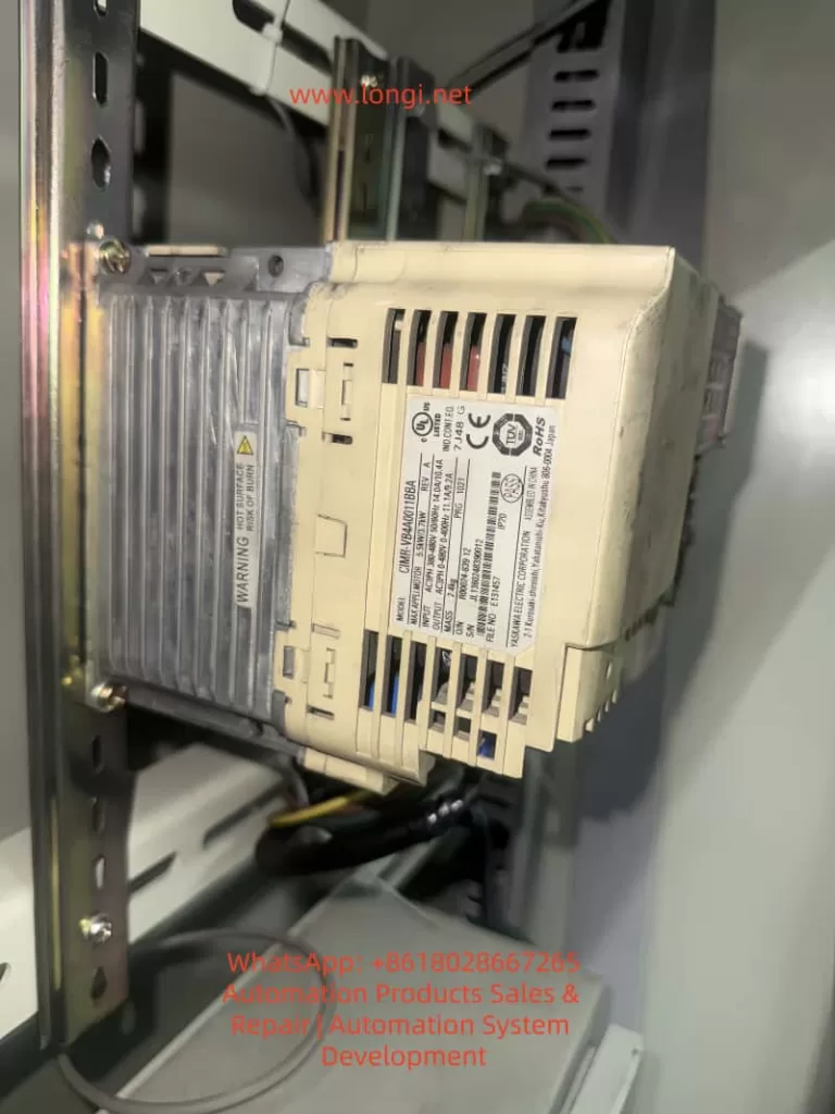
In modern industrial automation, inverters (VFDs) are not only used for motor speed control but also serve as vital communication nodes between field devices and PLCs or supervisory systems. The Yaskawa V1000 series, as a compact vector control inverter, is widely applied in conveyors, fans, pumps, compressors, and other equipment due to its stable performance and rich features.
However, many engineers encounter a common issue during commissioning: Why can’t I find H5-01 or H5-02 communication parameters in the V1000 menu?

This article will provide a systematic explanation from the perspective of communication card hardware requirements, panel operation, step-by-step key procedures, and troubleshooting methods. After reading, you will fully understand how to access and correctly configure the H5 parameters on a V1000 inverter, enabling MEMOBUS (Modbus RTU) communication without confusion.
I. Communication Basics of the V1000 Inverter
1.1 Limitations of the Standard Model
The standard version of the V1000 does not include an RS-485 port by default. It only supports local operation through I/O terminals, such as start/stop signals and analog inputs. Therefore, if you search for H5-01 (slave address) or H5-02 (baud rate) in the parameter menu, you will not find the H5 parameter group.
1.2 Necessity of Expansion Cards
To enable communication, dedicated option cards must be installed, such as:
- SI-485: RS-485 (Modbus RTU) communication card
- SI-232: RS-232 communication card
- Other fieldbus option cards: Profibus-DP, DeviceNet, CANopen, CC-Link, etc.
Once installed, the inverter automatically activates the relevant parameter group and displays H5-01, H5-02, and other settings.
1.3 Installation Position of Expansion Cards
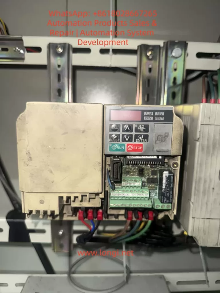
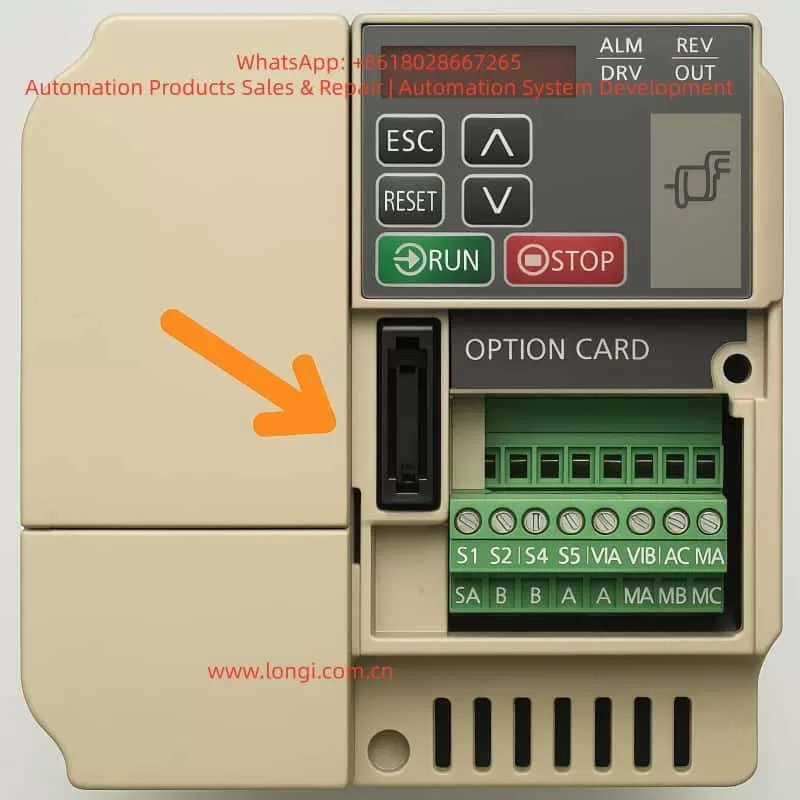
Above the control terminal block of the V1000, there is a long pin connector slot designed for option cards. Installation requires:
- Powering off and discharging the inverter to ensure safety.
- Removing the front cover to expose the slot.
- Inserting the communication card firmly into the slot and securing it with screws.
- Re-powering the inverter, which will then detect the card and load the H5 parameter group.

II. Operation Panel Types and Differences
2.1 Standard LED Operator
Most V1000 units are equipped with a simplified LED operator panel, which includes the following buttons:
- ESC (Exit/Back)
- RESET (Fault reset)
- ↑/↓ (Parameter navigation or value adjustment)
- ENTER (Confirm/Save)
- RUN/STOP (Start/Stop motor)
Unlike larger inverters, this panel does not have a dedicated PRG key. To enter the parameter menu, you need to press and hold ESC for about 2 seconds instead of pressing PRG.
2.2 Advanced LCD Operator (Optional)
Some models may be equipped with an LCD operator panel, which provides more advanced displays and shortcut keys. Regardless of the panel type, the process of accessing H5 parameters is the same, with only minor differences in button usage.

III. Step-by-Step Procedure to Access H5 Parameters
The following example is based on the standard LED operator commonly found on the V1000.
Step 1: Enter Parameter Mode
- After powering on, the display shows motor frequency, such as
0.00. - Press and hold the ESC key for 2 seconds to enter the parameter group selection mode.
- The screen will display a parameter code, for example
A1-01.
Step 2: Navigate to the H5 Parameter Group
- Use the ↑/↓ keys to scroll through parameter groups.
- You will see:
A1-xx→b1-xx→C1-xx… - Continue scrolling until you find
H5-01.
⚠️ Note: If the communication card is not installed or not recognized, the H5 parameter group will not appear.
Step 3: Configure H5-01 (Slave Address)
- When
H5-01is displayed, press ENTER. - The screen switches to the current value, for example
01. - Use ↑/↓ to set the slave address (range 0 to FFH).
- Press ENTER to save.
- The screen briefly flashes, then returns to
H5-01.
Step 4: Configure H5-02 (Baud Rate)
- Press ESC to return to the parameter list.
- Scroll to
H5-02. - Press ENTER to view the current value, e.g.,
03(9600bps). - Use ↑/↓ to select the desired baud rate:
0 = 1200bps3 = 9600bps4 = 19200bps8 = 115200bps
- Press ENTER to save.
Step 5: Return to Monitoring Mode
- Press ESC repeatedly until the display returns to the main frequency screen (e.g.,
0.00). - The parameters are now set.
IV. Common H5 Configuration Examples
4.1 Single-Inverter Communication
- H5-01 =
01(slave address = 1) - H5-02 =
4(baud rate = 19200bps) - Configure the PLC master with address 01 and baud rate 19200bps for communication.
4.2 Multi-Inverter Communication
- Several V1000 inverters connected on the same RS-485 bus.
- Each inverter must have a unique H5-01 value, e.g.,
01,02,03. - All devices must share the same H5-02 baud rate, e.g.,
19200bps. - Ensure termination resistors are enabled on both ends of the bus.
4.3 Commissioning Notes
- A power cycle is required after parameter changes for them to take effect.
- If communication fails, check baud rate and slave address consistency, and confirm R+/R- wiring polarity.
V. Common Issues and Solutions
5.1 H5 Parameters Missing
Cause: Communication card not installed, or wrong card type.
Solution: Ensure SI-485 card is installed properly and compatible with V1000.
5.2 Parameter Changes Not Effective
Cause: Some parameters only apply after restart.
Solution: Power off and restart the inverter after changes.
5.3 Communication Interruption
Cause: Long cable runs or strong EMI interference.
Solution: Use shielded twisted pairs, ground the shield properly, and add termination resistors.
5.4 Panel Buttons Differ from Manual
Cause: Different operator versions (LED vs. LCD).
Solution: For LED panels, press and hold ESC; for LCD versions, PRG may be available.
VI. Conclusion
This article systematically explained how to access and configure H5-01 and H5-02 parameters on the Yaskawa V1000 inverter. From hardware requirements (communication card installation) to operator panel differences and detailed step-by-step key operations, all potential problems have been clarified.
In short:
- H5 parameters will not appear without a communication card.
- On LED operators, hold ESC to enter parameter mode.
- Always save changes and restart for them to take effect.
By mastering these procedures, engineers can easily configure V1000 inverters for Modbus RTU communication, ensuring seamless integration into automation systems.
