
Product Overview and Core Features
The MKS PDR-C-2C is a professional-grade power supply and digital readout system designed for industrial pressure monitoring and control applications. As a mature product from MKS Instruments, the PDR-C-2C features a standard half-rack mount design, integrating high-precision power supply and dual-channel pressure signal processing capabilities.
Core Features:
- Dual-Channel Pressure Monitoring: Connects to two independent pressure sensors for wide-range pressure monitoring.
- High-Precision Digital Display: 4½-digit LED panel meter provides readings accurate to 0.01%.
- Programmable Setpoint Control: Equipped with two independent setpoint relays for customizable trigger thresholds.
- Multi-Unit Display: Supports seven engineering units: mmHg, psi, kPa, mbar, inHg, inH₂O, cmH₂O.
- Stable Power Output: Provides ±15VDC/600mA dual outputs to meet most pressure sensor requirements.
- Auto Channel Switching: Intelligently monitors dual-channel pressure values and automatically switches to display the sensor data with the optimal range.
Compared to the single-channel version PDR-C-1C, the PDR-C-2C adds dual-sensor interfaces and intelligent channel management, making it ideal for applications requiring wide-range pressure monitoring. The system’s modular design ensures easy maintenance, with all key parameters adjustable directly from the front panel without the need for specialized tools.
Safety Operating Procedures
As an electronic measurement device, the MKS PDR-C-2C must be used in strict compliance with safety regulations to prevent personal injury and equipment damage.
Electrical Safety Warnings:
- Grounding Requirements: The device must be properly grounded through the grounding conductor of the power cord. Loss of protective grounding connection may result in all accessible conductive parts (including seemingly insulated knobs and controls) becoming live, posing an electric shock risk.
- Power Supply Considerations:
- Use only a power cord that meets specifications (conductor cross-sectional area ≥ 0.75mm²).
- Use only the specified fuse type (1ASB for 120VAC, ½ASB for 240VAC).
- Power voltage range: 117/234V ± 15%, 50-60Hz.
- High Voltage Warning: High voltages are present in cables and sensors when the controller is powered on. Non-professionals are prohibited from opening the device casing.
Operating Environment Requirements:
- Temperature Range: 0°C to 50°C.
- Ventilation Requirements: Ensure adequate airflow around the device.
- Prohibited Environments: Do not use in explosive environments unless the device is certified for such use.
Maintenance Safety:
- No Unauthorized Modifications: Do not install replacement parts or make any unauthorized modifications to the instrument.
- Professional Repairs: Component replacement and internal adjustments must be performed by qualified service personnel.
- Cleaning and Maintenance: Regularly inspect cables for wear and check the casing for visible damage.
Device Installation and Connection
Unpacking Inspection:
Upon receiving the PDR-C-2C device, perform the following checks:
- Inspect the packaging for any obvious signs of damage.
- Verify the packing list:
- Standard configuration: PDR-C-2C host, user manual.
- Optional accessories: Electrical connector accessory kit (PDR-C-2C-K1), interface cables.
If any damage is found, immediately notify the carrier and MKS. If the device needs to be returned to MKS, first contact the MKS Service Center to obtain an Equipment Return Authorization (ERA) Number.
Mechanical Installation:
The device features a standard 19-inch half-rack design. When installing, note the following:
- Ensure the installation location has sufficient space for heat dissipation (at least 5cm clearance on both sides recommended).
- Use appropriate rack mounting hardware to secure the device.
- Avoid installing in environments with strong vibrations or excessive dust.
Electrical Connections:
Power Connection Steps:
- Confirm that the voltage selection card at the rear of the device is set to match the local grid voltage.
- Insert a compliant power cord (conductor cross-sectional area ≥ 0.75mm²).
- Connect to a properly grounded power outlet.
Pressure Sensor Connection:
The PDR-C-2C provides two 6-position terminal block sensor interfaces. Wiring definitions are as follows:
| Terminal Position | Signal Definition | Standard Wire Color |
|---|---|---|
| 1 | Digital Ground (D GND) | Black |
| 2 | Analog Ground (A GND) | Black |
| 3 | +15V Power Output | Green |
| 4 | -15V Power Output | White |
| 5 | Pressure Signal Input | Red |
| 6 | Chassis Ground | Thick Black |
Grounding System:
The PDR-C-2C employs a three-ground system:
- Digital Ground (D GND): Power return path.
- Analog Ground (A GND): DC output signal return path.
- Chassis Ground: Device casing ground.
When connecting pressure sensors with only a two-ground system, connect D GND and A GND to the sensor’s common ground, then connect the PDR’s chassis ground to the sensor’s chassis ground.
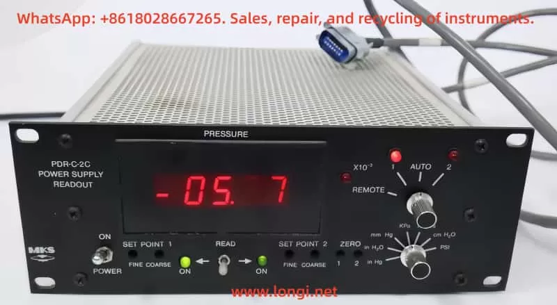
Front Panel Function Details
The PDR-C-2C front panel is designed for user-friendliness, with all commonly used functions directly operable without navigating complex menus.
Display Area:
- 4½-Digit LED Display: Red flat LED numeric display, range -19999 to 19999.
- x10⁻³ Indicator: Illuminates to indicate that the current display value should be multiplied by 0.001.
- Channel Indicator: Displays the currently active pressure channel (1 or 2).
Function Switches:
- Power Switch: Controls the main power supply to the device.
- Engineering Unit Selection Switch: Seven-position rotary switch for selecting units: mmHg, psi, kPa, mbar, inHg, inH₂O, cmH₂O.
- Channel Selection/Remote/Auto Switch (PDR-C-2C Specific):
- Position “1”: Fixed display of channel 1.
- Position “2”: Fixed display of channel 2.
- “AUTO”: Automatic channel switching mode.
- “REMOTE”: Allows remote channel selection via the rear interface.
Adjustment Controls:
- Zero Adjustment (Zero):
- Used for fine zero-point correction of pressure signals.
- Adjustment range: ±1.5% full scale.
- Absolute pressure gauges must be evacuated below their resolution before adjustment.
- Differential pressure gauges should undergo cross-porting.
- Setpoint Adjustment (Set Point):
- Independent Coarse and Fine adjustment knobs for each channel.
- Adjustment range: 0-100% full-scale pressure.
- Use the “Read Set Point” switch to view setpoint values in real-time.
- Setpoint Read Switch (Read Set Point):
- Middle position: Displays current pressure value.
- Left position: Displays channel 1 setpoint value.
- Right position: Displays channel 2 setpoint value.
- Automatically returns to the middle position after release.
Status Indicators:
- Setpoint Relay Indicators: LEDs illuminate to indicate that the corresponding relay is energized (pressure below setpoint).
- Overload Indicator: Blank display indicates that the input signal exceeds approximately 11V.
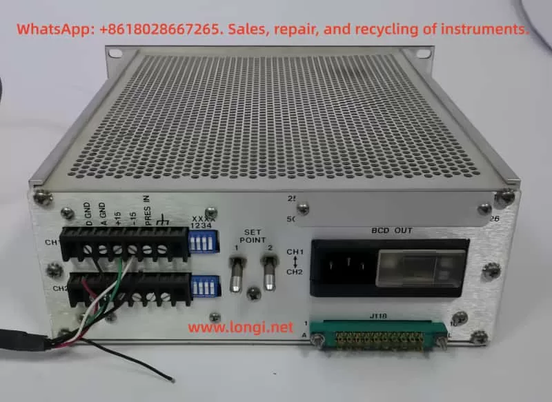
Rear Panel Interface Details
The PDR-C-2C rear panel contains multiple professional interfaces that extend system functionality.
Pressure Sensor Interfaces:
Two 6-position terminal blocks for connecting pressure sensors. Provides sensor operating power (±15V) and signal input. Each interface includes an independent decimal point selection switch.
Decimal Point Selection Switch:
4PST rocker switch for setting the display decimal point based on sensor range:
| Range | Switch Position |
|---|---|
| 1 | Switch 1 ON |
| 10 | Switch 2 ON |
| 100 | Switch 3 ON |
| 1000 | Switch 4 ON |
| 10000 | All OFF |
Note: Only one switch per channel should be in the ON position. Simultaneously closing multiple switches may result in abnormal display.
Power Interface Module:
- Accepts standard power cords.
- Built-in line filter.
- Voltage selection card visible behind a plastic window.
Steps for Voltage Replacement:
- Unplug the power cord and slide the plastic window to the left.
- Pull out the fuse holder to eject the fuse.
- Use a probe to remove the voltage selection card.
- Reinsert the card with the desired voltage facing outward.
- Install the appropriate fuse.
- Slide the window to the right.
- Insert the power cord.
Interface Connector (J118):
20-pin interface providing external control signal access:
| Pin | Function Description |
|---|---|
| 1 | Signal Ground |
| 2 | Digital Ground |
| 4 | Switched DC Output (Engineering Unit) |
| 6 | Setpoint 2 Relay Latch |
| 7 | Setpoint 1 Relay Latch |
| 8-10 | Setpoint 1 Relay Contacts (NO/NC/COM) |
| A | Channel 2 Range ID |
| B | Channel 1 Range ID |
| C | Remote Channel Selection |
| F | Channel 2 DC Output (0-10V) |
| H | Channel 1 DC Output (0-10V) |
| J-L | Setpoint 2 Relay Contacts |
BCD Output Connector (Optional):
Provides 5V BCD logic output for direct connection to digital devices for remote readout:
- Data update cycle approximately 0.5 seconds.
- Includes polarity, overrange, and other status signals.
- Enables multi-device bus sharing via control lines.
Operating Theory and Work Modes
Pressure Signal Processing Flow:
- Sensor signals are input through the rear panel terminal blocks.
- Signals pass through an input amplifier (U1) where fine zero-point correction is applied.
- Signals are split into three paths:
- Output buffer amplifiers (U2, U3) → Rear interface.
- Setpoint comparison circuit.
- Engineering unit scaling circuit → Display DVM.
Setpoint System:
- Two independent setpoint relays.
- Select which pressure signal to monitor via the rear panel switch (PDR-C-2C).
- Compare input signals with adjustable reference voltages (front panel controls).
- “Fail-Safe” logic: No power state = High-pressure state.
- Relay states can be remotely locked via the LATCH lines of the J118 interface.
Auto Channel Switching Logic (PDR-C-2C Specific):
- Comparator monitors channel 1 signal:
- 90% full-scale trigger.
- 100% full-scale trigger.
- Channel 1 < 90%: Display channel 1.
- Channel 1 > 100%: Automatically switch to channel 2.
- Channel 1 drops from > 100% to < 90%: Switch back to channel 1.
Power System:
- Provides ±15V for internal circuits and sensor power.
- Overload and overheating protection.
- Supplies precision reference voltage for comparators.
- Display DVM has its own +5V power supply.
Advanced Function Configuration
Engineering Unit Calibration:
- Short-circuit pressure input to signal ground.
- Connect DVM to analog ground and CH1 signal test point.
- Power on and adjust ZERO trimmer to display 0.000V ± 0.0005V on DVM.
- Apply a 10.0000V ± 0.0005V standard signal.
- Adjust the corresponding trimmer resistor based on the selected unit:
| Unit | Trimmer Resistor | Theoretical Display Value |
|---|---|---|
| mbar | R47 | 13332 |
| kPa | R47 | 13332 |
| mmHg | R49 | 10000 |
| psi | R44 | 19337 |
| cmH₂O | R55 | 13597 |
| inH₂O | R51 | 5353 |
| inHg | R53 | 3937 |
Remote Control Interface Applications:
Through the J118 interface, the following functions can be achieved:
- Remote Channel Selection: Input high level (or leave floating) on pin C to select channel 1, low level to select channel 2.
- Relay State Locking: Pull pins 6 or 7 low to lock the corresponding relay state.
- Analog Signal Monitoring:
- Pin H: Channel 1 0-10V output (with zero-point correction).
- Pin F: Channel 2 0-10V output.
- Pin 4: Output after engineering unit switching.
BCD Output Configuration (Optional Function):
- Data Ready Signal (DATA READY): High level indicates BCD data is valid.
- Bit Enable Control: Ground the DIGIT ENABLE line to read the corresponding BCD data bit.
- Polarity Output: Indicates the sign of the reading.
- Overrange Signal: Indicates that the input exceeds the range.
System Maintenance and Troubleshooting
Daily Maintenance:
- Regularly inspect cables for wear.
- Check the casing for visible damage.
- Clean ventilation holes to ensure good heat dissipation.
- Verify that all connectors are secure.
Fault Isolation Process:
Power Check:
- Measure ±15V outputs (relative to P GND).
- Normal range: 14.8-15.2V.
- Ripple < 10mVp-p.
- If abnormal, disconnect sensors and retest.
Signal Path Check:
- Use 10kΩ and 5.1kΩ resistors to simulate sensor input (should produce 9.6-10.3V).
- Measure voltages at various test points for normalcy.
- Check key operational amplifiers such as U1, U2, U3.
Setpoint Circuit Check:
- Confirm comparator input voltages (should follow setpoint adjustments).
- Check relay driver circuits (Q5, Q6).
- Test relay contact states.
Channel Selection Circuit Check (PDR-C-2C):
- Verify U4, U5 comparator switching points (9V and 10V).
- Check relay K1 switching state.
- Test remote selection logic (U6).
Common Issue Handling:
Issue 1: Inaccurate Display
- Check sensor connections.
- Verify decimal point switch settings.
- Recalibrate engineering units.
Issue 2: Relays Do Not Actuate
- Check setpoint adjustments.
- Measure comparator outputs.
- Verify relay driver voltages.
Issue 3: Auto Switching Fails
- Check if channel 1 signal reaches switching thresholds.
- Verify U4, U5 comparator operation.
- Test channel selection relay.
Technical Specifications and Model Descriptions
Physical Specifications:
- Dimensions: Standard half-rack width.
- Display: 4½-digit red LED.
- Weight: 3.2kg.
- Connectors: 20-pin interface, 6-position terminal block.
Electrical Specifications:
- Power Consumption: 65W (full load).
- Operating Voltage: 117/234V ± 15%, 50-60Hz.
- Power Output: ±15V @ 600mA.
- Analog Output: 0-10V (10kΩ load).
- Meter Accuracy: 0.01% reading ± 1 digit.
- Input Impedance: 900kΩ.
Setpoint Specifications:
- Relay Configuration: Single-pole double-throw (SPDT).
- Contact Rating: 2A @ 28VDC or 1A @ 120VAC.
- Hysteresis: 0.5% full scale.
- Adjustment Range: 100% full scale.
Model Coding:
PDRCXXYYY format:
- XX: Channel count (2C indicates dual-channel).
- YYY: Options (BCD indicates BCD output, E indicates CE certification).
Application Cases and Best Practices
Wide-Range Pressure Monitoring System:
Configuration Recommendations:
- Connect a high-precision low-pressure sensor (e.g., 10Torr) to channel 1.
- Connect a large-range sensor (e.g., 1000Torr) to channel 2.
- Set to “AUTO” mode for seamless range switching.
- Use setpoint 1 for low-pressure alarms and setpoint 2 for high-pressure alarms.
Industrial Process Control Integration:
Integration Scheme:
- Connect to PLC via the J118 interface.
- Use 0-10V outputs for pressure monitoring.
- Obtain relay states via digital lines.
- Remotely switch display channels.
- Connect BCD interface to digital recorders.
- Use setpoints to control safety valves or alarms.
Maintenance Tips:
- Regular Calibration:
- Zero-point calibration at least annually.
- Full-scale calibration every two years.
- Sensor Connection:
- Use shielded cables to reduce interference.
- Avoid running parallel to power lines.
- Environmental Control:
- Keep the working environment clean.
- Control ambient temperature within recommended ranges.
Appendix: Compatible Sensors and Accessories
Compatible Pressure Sensors:
MKS Baratron Series Compatible Sensors:
| Model | Remarks |
|---|---|
| 121 | |
| 221-224 | |
| 622-628 | 628 only supports single-channel |
| 722 |
Recommended Accessories:
- Electrical Connection Kit: PDR-C-2C-K1.
- Includes all necessary connectors for installation.
- Provides spare fuses.
- Interface Cables:
- 20-pin interface extension cable.
- BCD output cable.
- Calibration Tools:
- Precision voltage source.
- High-precision digital multimeter.
By systematically studying this guide, users should be able to fully master the various functions and operating methods of the MKS PDR-C-2C Power Digital Readout, leveraging its high-performance advantages in practical applications to provide reliable solutions for industrial pressure monitoring and control.