Posted on

Comprehensive User Guide for Hash HQ30D Series Dissolved Oxygen Meters

Chapter 1: Product Overview and Technical Specifications

1.1 Introduction to HQ30D Series Products

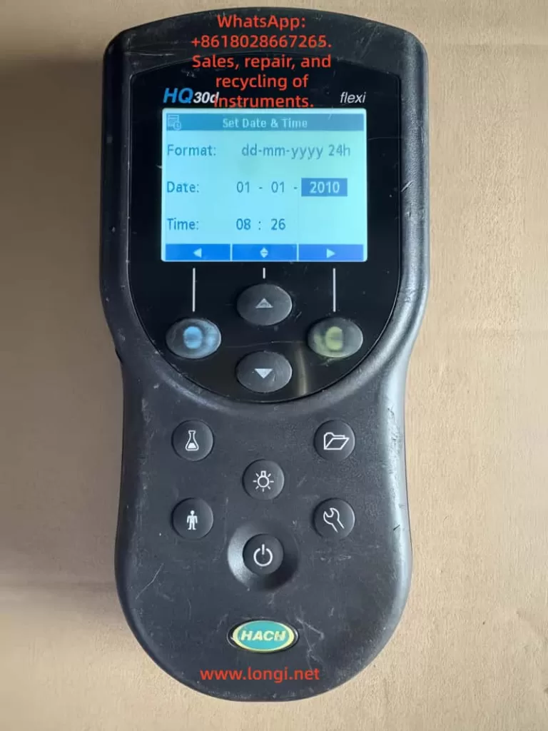
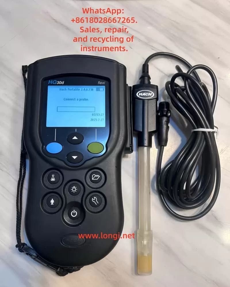
The Hash HQ30D series dissolved oxygen meters are high-performance portable instruments developed by Hash Company. Utilizing advanced polarographic sensor technology, these meters are widely applied in environmental monitoring, wastewater treatment, aquaculture, and scientific research. Renowned for their high precision, stability, and portability, the HQ30D series meets the dissolved oxygen measurement needs in various complex environments. The series includes multiple models, allowing users to select the most suitable one based on their requirements. All models employ the same core measurement technology, ensuring consistent and reliable results.

1.2 Key Technical Specifications

Measurement Performance Indicators:

  • Measurement Range: 0–20 mg/L (ppm) or 0–200% saturation
  • Resolution: 0.01 mg/L or 0.1% saturation
  • Accuracy: ±0.1 mg/L or ±1.5% of the reading (whichever is greater)
  • Response Time: <30 seconds to reach 90% of the final value (at 25°C water sample)

Environmental Adaptability:

  • Operating Temperature Range: 0–50°C
  • Storage Temperature Range: -20–60°C
  • Protection Class: IP67 (fully dustproof and waterproof for short-term immersion)
  • Power Supply: 6-12V DC adapter or 4 AA alkaline batteries
  • Battery Life: Approximately 40 hours of continuous use (with new batteries)

Physical Characteristics:

  • Host Dimensions: 215 × 87 × 42 mm
  • Weight: Approximately 520 g (including batteries)
  • Display: 4-digit LCD with backlight

Chapter 2: Instrument Components and Installation

2.1 Standard Accessories List

Standard Configuration:

  • HQ30D host unit (1)
  • LDO101 dissolved oxygen electrode (1)
  • Power adapter (input: 100-240V AC, output: 6-12V DC)
  • 4 AA alkaline batteries (pre-installed)
  • Portable carrying case (1)
  • User manual and certificate of conformity (1 each)

Optional Accessories:

  • Spare electrode membrane kit (including electrolyte)
  • BOD measurement kit
  • Dissolved oxygen standard calibration solution set
  • Data cable and printing accessories

2.2 Instrument Assembly Steps

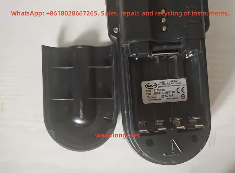
Battery Installation Procedure:

  1. Place the instrument upside down on a stable surface.
  2. Locate the battery compartment cover at the bottom and slide to unlock.
  3. Insert 4 AA batteries according to the polarity markings inside the compartment.
  4. Ensure proper battery contact and close the compartment cover.

Electrode Connection Method:

  1. Remove the electrode protective cap.
  2. Insert the electrode into the dedicated interface on the top of the host unit.
  3. Rotate the locking ring clockwise until securely fastened.
  4. Check the connection for stability and ensure no loosening.

Initial Use Preparation:

  • Activate the new electrode by soaking it in clean water for 2-4 hours.
  • Perform a complete calibration procedure before the first use.
  • Check the connections of all components for firmness.

Chapter 3: Basic Operation and Calibration

3.1 Power-On and Interface Navigation

Power-On Procedure:

  1. Press and hold the power button for 2 seconds to start the instrument.
  2. After system self-check, the main interface will be displayed.
  3. The default display shows the dissolved oxygen concentration (mg/L).

Interface Functional Areas:

  • Main Display Area: Real-time measurement value
  • Status Indicator Area: Battery level, calibration status, and other icons
  • Unit Display: Current measurement unit (mg/L or %)

Basic Button Functions:

  • Power Button: Power on/off and backlight activation
  • Mode Button: Switch between display modes
  • Calibration Button: Enter calibration program
  • Setting Button: Parameter configuration menu
  • Up/Down Buttons: Numerical adjustment and menu navigation

3.2 Zero Calibration Procedure

Preparation:

  • Prepare a zero-oxygen solution (0.25 g anhydrous sodium sulfite dissolved in 250 mL distilled water).
  • Ensure the electrode is clean and free from contamination.
  • Power on the instrument and allow it to warm up for 5 minutes.

Calibration Steps:

  1. Immerse the electrode in the zero-oxygen solution.
  2. Press the calibration button to enter the calibration menu.
  3. Select “Zero Calibration.”
  4. Wait for the reading to stabilize (approximately 3-5 minutes).
  5. Confirm that the calibration value displays 0.00 mg/L.
  6. Press the confirm button to complete the zero calibration.

3.3 Full-Scale Calibration Procedure

Preparation:

  • Prepare a saturated dissolved oxygen water sample (vigorously shake for 5 minutes) or use a dedicated saturated oxygen standard solution.
  • Ensure the water sample temperature is stable at 20-25°C.

Calibration Steps:

  1. Immerse the electrode in the saturated oxygen water sample.
  2. Press the calibration button to enter the calibration menu.
  3. Select “100% Calibration.”
  4. Gently stir the electrode to ensure water sample flow.
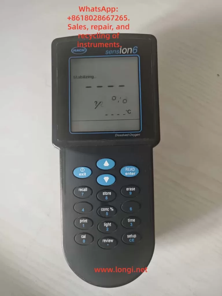
  5. Wait for the reading to stabilize (display shows “Stabilizing…”).
  6. Confirm that the reading is close to the theoretical saturation value.
  7. Press the confirm button to complete the full-scale calibration.

Chapter 4: Measurement Operation and Data Processing

4.1 Standard Measurement Procedure

Standard Measurement Steps:

  1. Immerse the electrode in the water sample to be tested.
  2. Ensure the electrode is in full contact with the water sample.
  3. Gently stir the electrode (approximately 2-3 times per second).
  4. Wait for the reading to stabilize (approximately 30-60 seconds).
  5. Record the measurement result.

Precautions:

  • Avoid vigorous stirring to prevent bubble formation.
  • Keep the electrode membrane surface clean.
  • Recommend measuring at a depth of 5-10 cm below the water surface.
  • Avoid direct sunlight exposure to the measurement area.

4.2 Data Recording and Storage

Manual Data Recording:

  1. After the measurement value stabilizes, press the storage button.
  2. Enter the sample number (optional).
  3. The measurement time and value will be automatically recorded.
  4. Add remarks (such as sampling location) if necessary.

Automatic Storage Function:

  • Set up timed automatic storage.
  • Storage interval adjustable from 1-60 minutes.
  • Maximum storage capacity of 500 data sets.

Data Query Method:

  1. Press the menu button to enter data management.
  2. Select “Data Review.”
  3. Search for records by date or number.
  4. View detailed measurement information.

4.3 Data Export and Printing

Computer Connection:

  1. Connect the instrument to a PC using a dedicated data cable.
  2. Install Hash data management software.
  3. Set communication parameters (9600 baud rate).
  4. Export data in Excel or text format.

Printing Output:

  1. Connect a compatible micro-printer.
  2. Select the data to be printed.
  3. Print single measurements or batch data.
  4. Printed content includes measurement values, time, and other information.

Chapter 5: Advanced Function Applications

5.1 BOD Measurement Mode

BOD5 Measurement Preparation:

  • Prepare a 300 mL BOD incubation bottle.
  • Collect representative water samples.
  • Dilute as necessary.

Measurement Steps:

  1. Measure the initial DO value (D1) of the sample.
  2. Seal the incubation bottle and place it in a 20 ± 1°C environment.
  3. After 5 days, measure the final DO value (D2).
  4. Calculate BOD5 = D1 – D2 (considering dilution factor).

Precautions:

  • Use a dedicated BOD bottle cap to ensure sealing.
  • Avoid light exposure during incubation.
  • Verify high BOD samples through multiple dilutions.

5.2 Salinity and Barometric Pressure Compensation

Salinity Compensation Setting:

  1. Press the setting button to enter the parameter menu.
  2. Select “Salinity Compensation.”
  3. Enter the actual salinity value of the water sample (0-40 ppt).
  4. Confirm to automatically apply the compensation algorithm.

Barometric Pressure Compensation Setting:

  1. Enter the setting menu and select “Barometric.”
  2. Manually enter the local barometric pressure value or select “Auto” to use the built-in sensor.
  3. Confirm to automatically adjust saturation calculations.

Temperature Compensation:

  • Automatically compensates based on the built-in temperature sensor.
  • Ensure the temperature probe is clean and free from contamination.
  • Check the temperature sensor if abnormal temperature readings are displayed.

Chapter 6: Maintenance and Troubleshooting

6.1 Daily Maintenance Points

Electrode Maintenance:

  • Replace the electrolyte and membrane kit monthly.
  • Clean the electrode surface after use.
  • Keep the electrode moist during short-term storage.
  • Store dry during long-term storage.

Instrument Cleaning:

  • Regularly wipe the exterior with a damp cloth.
  • Avoid using organic solvents.
  • Keep the interface dry and clean.
  • Check the battery compartment for corrosion.

Calibration Recommendations:

  • Check the zero point before daily use.
  • Perform full-scale calibration weekly.
  • Recalibrate after replacing the electrolyte.
  • Calibrate before use after long-term storage.

6.2 Common Fault Handling

Display Issues:

  • No display: Check battery/power connections.
  • Blurry display: Replace batteries or adjust contrast.
  • Backlight not illuminated: Check settings or battery level.

Measurement Abnormalities:

  • Unstable readings: Clean the electrode and check connections.
  • Slow response: Replace the electrolyte and membrane.
  • Calibration failure: Check calibration solution and confirm electrode status.

Error Codes:

  • Err 1: Sensor failure, check the electrode.
  • Err 2: Out of range, dilute the sample.
  • Err 3: Calibration error, recalibrate.
  • Err 4: Temperature sensor abnormality.

Chapter 7: Safety Regulations and Technical Support

7.1 Safety Operation Regulations

Electrical Safety:

  • Use only the original power adapter.
  • Do not use Ni-Cd rechargeable batteries.
  • Avoid charging in humid environments.

Chemical Safety:

  • Wear protective equipment when handling chemical reagents.
  • Rinse immediately if electrolyte contacts the skin.
  • Dispose of waste chemicals according to regulations.

Operational Safety:

  • Do not immerse the instrument in deep water.
  • Avoid strong vibrations or drops.
  • Avoid prolonged use in high-temperature environments.

7.2 Service and Support

Warranty Policy:

  • Host unit warranty period: 12 months.
  • Electrode warranty period: 6 months.
  • Damage caused by human factors is not covered by the warranty.

Repair Services:

  • Authorized repair centers nationwide provide services.
  • Provide the product serial number for repairs.
  • Non-professionals should not disassemble the instrument.

Chapter 8: Practical Application Tips

8.1 Methods to Improve Measurement Accuracy

Sample Handling Techniques:

  • Allow the sample to stand for 2-3 minutes before measurement.
  • Maintain stable sample temperature.
  • Avoid gas exchange during sample transfer.

Electrode Usage Techniques:

  • Regularly polish the electrode surface.
  • Keep the membrane moist during storage.
  • Avoid scratching the membrane surface.

Environmental Control Points:

  • Avoid strong electromagnetic interference sources.
  • Maintain stable temperature in the measurement environment.
  • Accurately set compensation for high-salinity samples.

8.2 Handling Special Application Scenarios

Low Dissolved Oxygen Measurement:

  • Use fresh zero-oxygen solution for calibration.
  • Extend the stabilization time.
  • Use a flow measurement cell to reduce interference.

High-Salinity Water Samples:

  • Accurately measure and input the salinity value.
  • Consider using a high-salinity dedicated electrode.
  • Increase calibration frequency.

Flowing Water Body Measurement:

  • Use a flow adapter to fix the electrode.
  • Select representative measurement positions.
  • Avoid turbulence and bubble interference.

Conclusion

The Hash HQ30D series dissolved oxygen meters are comprehensive and user-friendly professional water quality analysis instruments. Through the systematic introduction in this guide, users should be able to master the various functions and maintenance points of the instrument proficiently. Correct usage methods and regular maintenance not only ensure the accuracy of measurement data but also extend the instrument’s service life.

As a key indicator in water quality monitoring, accurate dissolved oxygen measurement is crucial for water environment management. We hope this guide helps users fully leverage the performance advantages of the HQ30D dissolved oxygen meters, providing reliable technical support for water quality monitoring work. For further technical assistance, please feel free to contact Hash Company’s professional service team at any time.

Posted on

Comprehensive User Guide for Hach Sension6 Portable Dissolved Oxygen Meter

Preface: Overview of Dissolved Oxygen Measurement Technology and Instruments

Dissolved oxygen (DO) is a crucial parameter in water quality monitoring, reflecting the self-purification capacity of water bodies and the health of ecosystems. The Hach Sension6 portable dissolved oxygen meter employs polarographic sensor technology, offering a measurement range of 0-20 mg/L (ppm) and 0-200% saturation, with an accuracy of 0.01 mg/L and 0.1% saturation. It supports dual power supply options (6-12V adapter or 4 AA alkaline batteries), complies with an IP67 protection rating, and features built-in data storage functionality. Data can be transferred to a computer or printer via an RS232 interface. This guide aims to assist users in comprehensively mastering the instrument’s operation, maintenance, and troubleshooting methods.

Chapter 1: Instrument Structure and Function Details

1.1 Instrument Composition and Standard Accessories

Standard Configuration:

  • Main unit (including electrode holder)
  • Dissolved oxygen electrode
  • Power adapter (Product No.: 9185600)
  • 4 AA alkaline batteries
  • Data transfer cable (RS232 port, black)
  • Operation manual and certificate of conformity

Optional Accessories:

  • BOD measurement kit (Product No.: 51971-00)
  • 100 mg/L dissolved oxygen standard solution (100 mL, Product No.: 21503-42)
  • Citizen PN60 micro-printer (Product No.: 26687-00)
  • Spare dissolved oxygen electrode membrane (4/pkg, Product No.: 27584-00)

1.2 Instrument Technical Specifications

Measurement Performance:

  • Measurement range: 0~20 mg/L (ppm), 0~200% saturation
  • Resolution: 0.01 mg/L, 0.1% saturation
  • Accuracy: ±0.1 mg/L or ±1.5% of reading (whichever is greater)
  • Response time: <30 seconds to reach 90% of final value (at 25°C water sample)

Environmental Adaptability:

  • Operating temperature: 0~50°C
  • Storage temperature: -20~60°C
  • Protection rating: IP67 (dust-tight and waterproof)
  • Power supply: 6-12V DC adapter or 4 AA alkaline batteries
  • Battery life: Approximately 6 months (under normal use)

Physical Characteristics:

  • Dimensions: 21.2 × 8.7 × 4.2 cm
  • Weight: Approximately 500 g (including batteries)
  • Display: 4-digit LCD, 1.5 cm character height

1.3 Keyboard Function Details

Main Function Keys:

  • SETUP/CE: Enter setup menu or clear current input
  • READ/ENTER: Confirm selection or start measurement
  • EXIT: Exit current menu or cancel operation

Auxiliary Function Keys:

  • CONC%: Switch between concentration (mg/L) and saturation (%) display
  • STORE: Store current measurement data
  • RECALL: Retrieve historically stored data
  • TIME/DATE: View or set time and date
  • PRINT: Print data via RS232 interface

Navigation Keys:

  • ▲/▼: Move up or down in the menu to select items

Chapter 2: Initial Instrument Setup and Calibration

2.1 Power Management and Battery Installation

Battery Installation Steps:

  1. Place the instrument upside down on a soft pad.
  2. Open the battery compartment cover at the bottom.
  3. Insert 4 AA alkaline batteries according to the marked direction (do not use Ni-Cd rechargeable batteries).
  4. Close the battery compartment cover.

Notes:

  • The display will show “LOW BATTERY” when the battery level is low.
  • It is recommended to remove the batteries if the instrument is not in use for an extended period.
  • After replacing the batteries, the time and date need to be reset.

2.2 Basic Parameter Settings

Date Setting:

  1. Press the SETUP/CE key to enter the setup menu.
  2. Select the “Date” option.
  3. Enter the current date (format: MM/DD/YY).
  4. Press READ/ENTER to confirm.

Time Setting:

  1. In the setup menu, select “Time”.
  2. Enter the time in 24-hour format (e.g., 14:00).
  3. Press READ/ENTER to confirm.

Unit Setting:

  1. Enter the setup menu and select “Units”.
  2. Choose mg/L or % saturation as the default display unit.
  3. Press READ/ENTER to confirm.

2.3 Sensor Installation and Preparation

Dissolved Oxygen Electrode Installation:

  1. Insert the electrode into the electrode socket on the top of the instrument.
  2. Rotate the locking ring clockwise to secure the electrode.
  3. Ensure the electrode is firmly connected to the instrument.

Electrode Activation:

  • For initial use or after long-term storage, immerse the electrode in water for at least 2 hours.
  • Regularly check if the electrode membrane is intact, without damage or contamination.
  • Keep the surface of the electrode membrane clean and avoid scratching it.

Chapter 3: Dissolved Oxygen Measurement Operation Process

3.1 Zero Calibration (Zero Oxygen Calibration)

Preparation of Zero Oxygen Solution:

  • Take 250 mL of distilled water and add 0.25 g of anhydrous sodium sulfite.
  • Stir until completely dissolved (to create a zero-oxygen environment).

Calibration Steps:

  1. Immerse the electrode in the zero-oxygen solution.
  2. Press the SETUP/CE key to enter the setup menu.
  3. Select “Calibration” → “Zero Cal”.
  4. Wait for the reading to stabilize (about 3-5 minutes).
  5. Press READ/ENTER to confirm the zero point.
  6. Press EXIT to exit the calibration mode.

3.2 Full-Scale Calibration (100% Saturation Calibration)

Preparation of Saturated Oxygen Water:

  • Take 150 mL of distilled water and shake vigorously for 5 minutes.
  • Alternatively, use a specially prepared saturated dissolved oxygen standard solution.

Calibration Steps:

  1. Immerse the electrode in the saturated oxygen water.
  2. Press the SETUP/CE key to enter the setup menu.
  3. Select “Calibration” → “100% Cal”.
  4. Wait for the reading to stabilize (display “Stabilizing…”).
  5. Press READ/ENTER to confirm the full-scale value.
  6. Press EXIT to exit the calibration mode.

3.3 Sample Measurement

Standard Measurement Process:

  1. Immerse the electrode in the water sample to be tested.
  2. Gently stir the electrode to keep the water sample flowing (avoid generating bubbles).
  3. Wait for the reading to stabilize (about 30-60 seconds).
  4. Press the CONC% key to switch between mg/L and % saturation display.
  5. Record the measurement result.

Notes:

  • Avoid direct sunlight on the sample during measurement.
  • Keep the temperature of the water sample stable (temperature changes affect dissolved oxygen).
  • For high-salinity samples, set the salinity compensation.

3.4 Salinity and Barometric Pressure Compensation

Salinity Compensation Setting:

  1. Press SETUP/CE to enter the setup menu.
  2. Select the “Salinity” option.
  3. Enter the salinity value of the sample (0-42 ppt).
  4. Press READ/ENTER to confirm.

Barometric Pressure Compensation Setting:

  1. Enter the setup menu and select “Barometer”.
  2. Enter the local atmospheric pressure value (mmHg or inHg).
  • Or select “Auto” to automatically obtain barometric pressure data.
  1. Press READ/ENTER to confirm.

Chapter 4: Advanced Function Applications

4.1 BOD Measurement Mode

BOD Measurement Steps:

  1. Prepare a 300 mL BOD sample bottle.
  2. Initially measure the DO value of the sample and record it.
  3. Place the sample bottle in a 20°C incubator for 5 days.
  4. After 5 days, measure the DO value again.
  5. Calculate the BOD value (initial DO – final DO).

Notes:

  • Use a dedicated BOD bottle cap to prevent gas exchange.
  • Keep the incubation temperature constant at 20 ± 1°C.
  • For high-BOD samples, appropriate dilution may be required.

4.2 Data Storage and Retrieval

Data Storage:

  1. After the measurement result is displayed, press the STORE key.
  2. Enter the sample number (automatically or manually).
  3. Press READ/ENTER to confirm storage.

Data Retrieval:

  1. Press the RECALL key to enter the data review menu.
  2. Use the ▲/▼ keys to select the sample number.
  3. Press READ/ENTER to view detailed data.
  4. Press TIME/DATE to view the storage time.

Data Management:

  • Can store up to 99 sets of measurement data.
  • Supports deleting a single set of data by number.
  • Can delete all stored data at once.

4.3 Data Output and Printing

RS232 Interface Connection:

  1. Use the dedicated data cable to connect the instrument to a computer/printer.
  2. Set the communication parameters (9600 baud rate, 8 data bits, no parity).
  3. Press the PRINT key to send data.

Printing Options:

  • Print the current measurement value.
  • Print specified stored data.
  • Print all stored data.

Computer Connection:

  1. Install the HachLink™ software.
  2. Set up a hyperterminal to receive data.
  3. Enable automatic data collection and storage.

Chapter 5: Instrument Maintenance and Troubleshooting

5.1 Daily Maintenance Points

Electrode Maintenance:

  • Regularly replace the electrolyte and membrane (recommended every 1-2 months).
  • Clean the electrode surface to avoid contamination.
  • Keep the electrode moist during short-term storage.
  • Store the electrode dry during long-term storage.

Instrument Cleaning:

  • Wipe the outer shell with a damp cloth.
  • Avoid using organic solvents.
  • Keep the keyboard and interface dry.

Calibration Recommendations:

  • Perform zero calibration before using the instrument each day.
  • Perform full-scale calibration once a week.
  • Recalibrate after replacing the electrolyte or membrane.

5.2 Common Faults and Troubleshooting

Display Problems:

  • No display: Check battery installation and power connection.
  • Blurry display: Adjust the contrast or replace the batteries.
  • “LOW BATTERY”: Replace all 4 batteries.

Measurement Abnormalities:

  • Unstable readings: Check the electrode connection and clean the electrode.
  • Slow response: Replace the electrolyte and membrane.
  • Calibration failure: Check the calibration solution and confirm the electrode status.

Error Codes:

  • Err 1: Sensor failure, check the electrode connection.
  • Err 2: Out of measurement range, dilute the sample.
  • Err 3: Calibration error, recalibrate.

Chapter 6: Safety Regulations and Quality Assurance

6.1 Safety Operation Regulations

Danger Warnings:

  • Do not use Ni-Cd rechargeable batteries as there is a risk of explosion.
  • Avoid contact of the electrode with strong acid and alkali solutions.
  • Do not immerse the instrument in water (although it has an IP67 protection rating).

Operation Precautions:

  • Wear protective equipment when handling chemical reagents.
  • Use standard solutions according to the instructions.
  • Dispose of used electrolyte as hazardous waste.

6.2 Quality Assurance and Service Support

Warranty Policy:

  • Standard warranty period is 1 year (from the date of shipment).
  • Covers material and workmanship defects.
  • Unauthorized disassembly will void the warranty.

Maintenance Services:

  • Users are not allowed to repair any parts other than the batteries by themselves.
  • Contact an authorized service center for handling.
  • Provide the instrument model and serial number when requesting maintenance.

Chapter 7: Practical Application Tips

7.1 Tips for Improving Measurement Accuracy

Sample Handling:

  • Avoid vigorous shaking to prevent bubble generation.
  • Keep the sample temperature stable.
  • Allow the electrode to acclimate to the sample temperature before measurement.

Electrode Maintenance:

  • Regularly replace the electrolyte and membrane.
  • Keep the membrane moist during storage.
  • Clean the electrode gently with a soft cloth.

Environmental Control:

  • Avoid strong electromagnetic interference.
  • Keep the measurement environment temperature stable.
  • Set the correct salinity compensation for high-salinity samples.

7.2 Handling Special Application Scenarios

Low Dissolved Oxygen Measurement:

  • Use zero calibration to improve accuracy at the low end.
  • Extend the stabilization time.
  • Avoid contact between the sample and air.

High-Salinity Water Samples:

  • Accurately set the salinity compensation value.
  • Consider using a dedicated high-salinity electrode.
  • Increase the calibration frequency.

Flowing Water Body Measurement:

  • Ensure sufficient contact between the electrode and the water.
  • Use a flow cell attachment.
  • Avoid measurement positions with eddies or bubbles.

Conclusion

The Hach Sension6 portable dissolved oxygen meter is a fully functional and easy-to-operate professional water quality analysis instrument. Through the systematic introduction in this guide, users should be able to proficiently master all functions of the instrument, from basic operations to advanced applications. Correct operation methods and regular maintenance can not only ensure the accuracy of measurement data but also extend the service life of the instrument. When encountering problems that cannot be resolved, promptly contact the professional technical service personnel of Hach Company to avoid improper operation causing instrument damage or data loss.

Dissolved oxygen monitoring plays an irreplaceable role in water environment protection, aquaculture, and sewage treatment. It is hoped that this guide can help users fully leverage the performance advantages of the Sension6 portable dissolved oxygen meter, providing reliable technical support for water quality monitoring work and jointly safeguarding the health of our water environment.

Posted on

Comprehensive User Guide for Hach DR1010 COD Determinator

Preface: The Importance of COD Determination Technology and an Overview of the Instrument

Chemical Oxygen Demand (COD) is a crucial indicator in water quality monitoring, reflecting the extent of water pollution caused by reducing substances. The Hach DR1010 COD Determinator, a professional water quality analysis instrument, is widely used in environmental monitoring, sewage treatment, and industrial wastewater testing. This guide aims to comprehensively analyze the operational procedures, functional features, maintenance, and troubleshooting methods of the DR1010 based on the user manual, helping users obtain accurate and reliable test results.

Developed by Hach Company, the DR1010 COD Determinator is controlled by a microprocessor and features an LED light source, suitable for laboratory or on-site measurements. It has four built-in COD test programs, supports user-created curves, and can store up to 40 user programs. The instrument offers flexible power supply options, including a 6V adapter or four AA alkaline dry batteries, operates within a temperature range of 0 to 50°C, and meets the IP41 protection standard.

Chapter 1: Instrument Structure and Function Details

1.1 Instrument Composition and Standard Accessories

The standard configuration of the DR1010 COD Determinator includes:

  • Power adapter (Product No.: 9185600)
  • Data transfer cable (RS232 port, black)
  • Document bag (containing operation manual, method manual, and certificate of conformity)

Optional accessories:

  • COD test tubes (16mm × 100mm, with tube caps)
  • Data printing cable (RS232 port, gray)
  • DRB200 digestor
  • Bottle-top dispensers
  • Pipettes

1.2 Instrument Technical Parameters

  • Wavelength range: 420nm and 610nm dual wavelengths
  • Wavelength accuracy: ±1nm
  • Photometric measurement linearity: ±0.002A (0-1A)
  • Photometric measurement repeatability: ±0.005A (0-1A)
  • Light source: LED
  • Detector: Silicon photodiode
  • Data display: Four-digit LCD, 1.5 cm character height
  • Readout modes: % transmittance, absorbance, concentration
  • External output: RS232 serial port
  • Power supply: 190~240VAC/50Hz adapter or four AA alkaline batteries
  • Instrument dimensions: 24.0 × 19.8 × 12.0 cm
  • Instrument weight: 2 kg
  • Operating temperature: 0 to 50°C
  • Storage temperature: -20 to 60°C

1.3 Keyboard Function Details

Program Selection Keys:

  • High-range 2h: Selects the high-range two-hour digestion method; acts as the number key 7 in numeric mode.
  • Low-range 2h: Selects the low-range two-hour digestion method; acts as the number key 4 in numeric mode.
  • High-range rapid: Selects the high-range 15-minute digestion method; acts as the number key 1 in numeric mode.
  • Low-range rapid: Selects the low-range 15-minute digestion method; acts as the number key 1 in numeric mode.

Function Keys:

  • Print: Prints current data; acts as the number key 8 in numeric mode.
  • Save: Stores the current reading; acts as the number key 5 in numeric mode.
  • Historical data: Retrieves stored sample data; acts as the number key 2 in numeric mode.
  • Zero: Uses the current sample blank for zero adjustment; acts as the number key 0 in numeric mode.
  • Setup: Enters the setup menu; acts as the number key 9 in numeric mode.
  • Time/Date: Displays the current time or date; acts as the number key 6 in numeric mode.
  • Unit conversion: Converts between concentration, absorbance, and % transmittance; acts as the number key 3 in numeric mode.
  • Read: Reads and displays the sample concentration; inputs decimal points or switches between positive and negative signs in numeric mode.
  • Return: Cancels the current input or selection.
  • △/▽: Scrolls up and down within the menu.
  • Enter: Selects a menu item or accepts an input value.

Chapter 2: Initial Instrument Setup and Calibration

2.1 Battery Installation and Power Management

  • Turn the instrument over and ensure the sample cell is empty.
  • Open the battery compartment cover and install four AA alkaline batteries according to the markings.
  • Re-cover the battery compartment and turn the instrument back to its upright position.

Important Tips:

  • Use alkaline batteries. Do not use rechargeable Ni-Cd batteries.
  • Replace all batteries when changing them.
  • When the battery level is low, the LOW BATTERY icon will be displayed. Replace the batteries promptly.
  • It is recommended to remove the batteries if the instrument is not used for an extended period.

2.2 Date and Time Setup

Date Setup:

  • Press the “Setup” key to enter the SETUP menu.
  • Select the DATE option and input the four-digit year, month, and day.
  • Press the “Enter” key to confirm.

Time Setup:

  • In the SETUP menu, select the TIME option.
  • Input the time in 24-hour format.
  • Press the “Enter” key to confirm.

2.3 Proper Use of Sample Tubes

  • Wipe the outer surface of the sample tube with a lint-free cloth.
  • Insert the tube into the instrument’s tube holder, with the HACH logo facing the display.
  • Ensure consistent insertion direction for each measurement.
  • Check that the sample tube is clean and free of scratches before measurement.

Chapter 3: Detailed Instrument Operation Procedures

3.1 Basic Measurement Steps

Determinator Setup:

  • Upon startup, the instrument automatically enters the program used last time.
  • Press the corresponding program key to select a program and press the “Enter” key to confirm.

Sample Preparation:

  • Prepare the zero solution and the sample to be tested according to the program instructions.

Instrument Zeroing:

  • Place the blank solution in the sample cell.
  • Close the cover and press the “Zero” key.
  • When the instrument displays 0 and the READ icon appears, measurement can begin.

Sample Measurement:

  • Place the sample to be tested in the holder.
  • Close the cover and press the “Read” key.
  • The display shows the measurement result.
  • Press the “Unit conversion” key to switch the display mode.

3.2 Standard Curve Adjustment Method

  • Prepare standard solutions.
  • Measure the standard solutions as samples in the program.
  • After obtaining the readings, press the “Setup” key and scroll to the “STD” setting item.
  • Input the actual concentration of the standard solution and press the “Enter” key.

Notes:

  • Consider sample interference before adjustment.
  • After adjustment, test multiple concentration standard solutions to verify the applicability of the curve.
  • If the input calibration value is out of range, the instrument will emit a beep to indicate an error.

3.3 Data Storage and Retrieval

Data Storage:

  • After the measurement result is displayed, press the “Save” key.
  • The display shows the next available storage sequence number.
  • Press the “Enter” key to accept or input a specific sequence number.

Data Retrieval:

  • Press the “Historical data” key to enter the RECALL menu.
  • Use the “▽” or “△” key or numeric keys to select the sample sequence number.
  • Press the “Enter” key to display the stored data.

Chapter 4: Advanced Function Applications

4.1 User Program Creation Method

  • Press the “Setup” key and select the USER option.
  • Input the program number to be created (20-59).
  • Select the wavelength.
  • Prepare standard solutions and perform zero adjustment on the instrument.
  • Measure the absorbance values of the standard solutions.
  • Repeat the steps to complete the input of all standard points.
  • Press the “Return” key and select to store the program.

Key Points:

  • A minimum of 2 data points and a maximum of 12 are required.
  • At 420nm, the absorbance should decrease as the concentration increases.
  • At 610nm, the absorbance should increase as the concentration increases.
  • The instrument will ignore identical absorbance values and emit a beep.

4.2 Data Transmission and Printing

Printer Connection:

  • Connect the instrument and the printer using the gray data printing cable.
  • Press the “Print” key to manually initiate printing.

Computer Connection:

  • Connect the instrument and the computer using the black data transfer cable.
  • Set the super terminal parameters.
  • Start the text capture function.
  • Press the “Print” key to transmit data to a text file.

4.3 Batch Data Processing

  • Print all data: Select PRINT ALL in the SETUP menu.
  • Delete all data: Select ERASE ALL in the SETUP menu.
  • Data export: Transfer all data to a computer through the RS232 interface.

Chapter 5: Instrument Maintenance and Troubleshooting

5.1 Daily Maintenance Points

Cleaning and Maintenance:

  • Wipe the instrument’s outer shell with a damp cloth.
  • Promptly clean up any spilled reagents.
  • Clean the sample cell holder with a cotton swab.
  • Wipe the outer surface of the sample cell with lens paper or a soft, lint-free cloth.

Battery Management:

  • Replace low-battery cells promptly.
  • Remove the batteries if the instrument is not used for an extended period.
  • Reset the date and time after replacing the batteries.

Storage Conditions:

  • Storage temperature: -20 to 60°C
  • Relative humidity: Below 80% (at 40°C)
  • Avoid strong electromagnetic field environments.

5.2 Common Fault Exclusion

Error Codes and Solutions:

  1. Unable to set the instrument. Contact Hach customer service.
  2. Unable to read program data. Contact Hach customer service.
  3. Unable to write program data. Contact Hach customer service.
  4. Measurement battery error. Replace the batteries.
  5. Measurement A/D error. Contact Hach customer service.
  6. Measurement offset error. Check the installation of the light blocker.
  7. Low photometric intensity error. Check for light channel blockage or dilute the sample.
  8. Measurement value out of range. Confirm the installation of the instrument cover or contact customer service.

Other Common Problems:

  • Concentration out of range: Dilute the sample and re-measure.
  • Beep/error icon: Check the operational steps.
  • Low battery level: The LOW BATTERY icon is displayed. Replace the batteries promptly.

Chapter 6: Safety Regulations and Quality Assurance

6.1 Safety Operation Regulations

Hazard Levels:

  • Danger (DANGER): Situations that may lead to death or serious injury.
  • Caution (CAUTION): Situations that may lead to minor or moderate injury.
  • Note (NOTE): Information that requires special emphasis.

Key Safety Tips:

  • Review the Material Safety Data Sheet (MSDS) and be familiar with safety procedures when handling chemical samples.
  • The instrument should not be used for samples that are flammable or contain hydrocarbons.
  • Do not use Ni-Cd rechargeable batteries.
  • Do not open the instrument’s chassis without authorization.

6.2 Quality Assurance and Service Support

Quality Assurance:

  • Most products are guaranteed for at least one year from the shipping date.
  • The warranty covers defects in materials and manufacturing.

Repair Services:

  • Users should not attempt to repair any parts other than the batteries by themselves.
  • Contact an authorized Hach Company service center for repairs.

Chapter 7: Practical Application Tips and Experience Sharing

7.1 Best Practices for COD Measurement

Sample Handling Tips:

  • Ensure the sample is representative and mix it thoroughly before sampling.
  • Follow the digestion time and temperature requirements strictly.
  • Use reagents from the same batch for comparative measurements.

Methods to Reduce Errors:

  • Regularly verify the instrument’s accuracy using standard solutions.
  • Keep the sample tube clean.
  • Perform zero adjustment before each measurement.
  • Take the average of multiple measurements of the same sample.

7.2 Handling Special Application Scenarios

High-Salinity Sample Measurement:

  • May cause interference. It is recommended to conduct a spike recovery test.
  • Establish a specific calibration curve if necessary.

Low-Concentration Sample Measurement:

  • Use the low-range program to improve sensitivity.
  • Extend the measurement time or increase the sample volume.

Chapter 8: Instrument Verification and Compliance

8.1 Performance Verification Methods

Blank Test:

  • Measurement of ultrapure water should show 0mg/L COD.

Standard Sample Test:

  • Use COD standard solutions with known concentrations for verification.

Repeatability Test:

  • Measure the same sample multiple times and calculate the relative standard deviation.

Comparison Test:

  • Compare the results with standard methods or other instruments.

8.2 Compliance Certification

LED Safety:

  • Complies with EN60825-1 standard, Class 1 LED product.

Anti-Interference Characteristics:

  • Complies with EN 50082-1 general anti-interference standard.

EMC Electromagnetic Compatibility:

  • EN 61000-4-2 resistance to electrostatic discharge interference.
  • EN 61000-4-3 resistance to radiated RF electromagnetic field interference.
  • ENV 50204 resistance to digital telephone radiation.

Radio Frequency Emissions:

  • Complies with EN 55011 (CISPR 11) Class B emission limits.

Conclusion

The Hach DR1010 COD Determinator is a powerful and easy-to-use professional water quality analysis instrument. Through systematic learning of this guide, users should be able to master all the functions of the instrument, from basic operations to advanced applications. Correct operational methods and regular maintenance not only ensure the accuracy of measurement data but also extend the instrument’s service life. When encountering problems that cannot be resolved, users should promptly contact Hach Company’s professional technical service personnel to avoid improper operations that may cause instrument damage or data loss.

With the continuous improvement of environmental protection requirements, the importance of COD monitoring is becoming increasingly prominent. It is hoped that this guide will help users fully leverage the performance advantages of the DR1010 COD Determinator and provide reliable technical support for water quality monitoring and environmental protection work.

Posted on

Hach COD – 203 Online CODMn (Permanganate Index) Analyzer User Guide

I. Product Overview and Basic Principles

1.1 Product Introduction

The Hach COD – 203 online CODMn (permanganate index) analyzer is a precision instrument specifically designed for the automatic monitoring of the chemical oxygen demand (COD) concentration in industrial wastewater, river, and lake water bodies. Manufactured in accordance with the JIS K 0806 “Automatic Measuring Apparatus for Chemical Oxygen Demand (COD)” standard, this device employs fully automated measurement operations and adheres to the measurement principle of “Oxygen Consumption by Potassium Permanganate at 100°C (CODMn)” specified in the JIS K 0102 standard.

1.2 Measurement Principle

This analyzer utilizes the redox potential titration method to achieve precise determination of COD values through the following steps:

Oxidation Reaction: A定量 (fixed) amount of potassium permanganate solution is added to the water sample, which is then heated at 100°C for 30 minutes to oxidize organic and inorganic reducing substances in the water.
Residual Titration: An excess amount of sodium oxalate solution is added to react with the unreacted potassium permanganate, followed by titration of the remaining sodium oxalate with potassium permanganate.
Endpoint Determination: The mutation point of the redox potential is detected using a platinum electrode to calculate the amount of potassium permanganate consumed, which is then converted into the COD value.

1.3 Technical Features

  • Measurement Range: 0 – 20 mg/L to 0 – 2000 mg/L (multiple ranges available)
  • Measurement Cycle: 1 hour per measurement (configurable from 1 – 6 hours)
  • Flow Path Configuration: Standard configuration is 1 flow path with 1 range; optional 2 flow paths with 2 ranges
  • Measurement Methods: Supports acidic and alkaline methods (applicable to water samples with high chloride ion content)
  • Automation Level: Fully automated process including sampling, reagent addition, heating digestion, and titration calculation

II. Equipment Installation and Initial Setup

2.1 Installation Requirements

Environmental Requirements:

  • Temperature: 5 – 40°C
  • Humidity: ≤85% RH
  • Avoid direct sunlight, corrosive gases, and strong vibrations

Water Sample Requirements:

  • Temperature: 2 – 40°C
  • Pressure: 0.02 – 0.05 MPa
  • Flow rate: 0.5 – 4 L/min
  • Chloride ion limit: ≤2000 mg/L (for the 20 mg/L range)

Power and Water Supply:

  • Power supply: AC100V ± 10%, 50/60 Hz, maximum power consumption 550 VA
  • Pure water supply: Pressure 0.1 – 0.5 MPa, flow rate approximately 2 L/min

2.2 Equipment Installation Steps

Mechanical Installation:

  • Select a sturdy and level installation base.
  • Secure the equipment using four M12 × 200 anchor bolts.
  • Ensure the equipment is level and maintain a maintenance space of ≥1 m around it.

Pipe Connection:

  • Sampling pipe: Rc1/2 interface, recommended to use transparent PVC pipes (Φ13 or Φ16)
  • Pure water pipe: Rc1/2 interface, install an 80-mesh Y-type filter at the front end
  • Drain pipe: Rc1 interface, maintain a natural drainage slope of ≥1/50
  • Waste liquid pipe: Φ10 × Φ14.5 dedicated pipe, connect to a waste liquid container

Electrical Connection:

  • Power cable: 1.25 mm² × 3-core shielded cable
  • Grounding: Class D grounding (grounding resistance ≤100 Ω)
  • Signal output: Dual-channel isolated output of 4 – 20 mA/0 – 1 V

III. Reagent Preparation and System Preparation

3.1 Reagent Types and Preparation

Reagent 1 (Acidic Method):

  • Take 1000 g of special-grade silver nitrate.
  • Add pure water to reach a total volume of 5 L.
  • Store in a light-proof container and connect with a yellow hose.

Reagent 2 (Sulfuric Acid Solution):

  • Prepare 2 – 3 L of pure water in a container.
  • Slowly add 1.7 L of special-grade sulfuric acid (in 6 – 7 batches, with an interval of 10 – 20 minutes).
  • Add 5 mmol/L potassium permanganate dropwise until a faint red color is maintained for 1 minute.
  • Add pure water to reach 5 L and connect with a green hose.

Reagent 3 (Sodium Oxalate Solution):

  • Take 8.375 g of special-grade sodium oxalate (dried at 200°C for 1 hour).
  • Add pure water to reach 5 L and connect with a blue hose.

Reagent 4 (Potassium Permanganate Solution):

  • Dissolve 4.0 g of special-grade potassium permanganate in 5.5 L of pure water.
  • Boil for 1 – 2 hours, cool, and let stand overnight.
  • Filter and titrate to a concentration of 0.95 – 0.98.
  • Store in a 10 L light-proof container and connect with a red hose.

3.2 System Initial Preparation

Electrode Internal Solution Preparation:

  • Dissolve 200 g of potassium sulfate in 1 L of distilled water at 50°C to prepare a saturated solution.
  • Take the supernatant and dilute it with 1 L of distilled water.
  • Inject the solution into the comparison electrode container to fill one-third of its volume.

Heating Tank Oil Filling:

  • Inject approximately 500 mL of heat transfer oil through the hole in the heating tank cover.
  • The oil level should be between the two liquid level marks.

Pipe Flushing:

  • Open the sampling valve and pure water valve to expel air from the pipes.
  • Start the activated carbon filter (BV1 valve).
  • Set the flow rate to 1 L/min (PV7 valve).

IV. Detailed Operation Procedures

4.1 Power-On and Initialization

  • Turn on the power supply and confirm that the POWER indicator light is on.
  • Load the recording paper (76 mm wide thermal paper).
  • Perform Reagent 4 filling:
    • Enter the maintenance menu and select “Reagent 4 Injection/Attraction”.
    • Confirm that the liquid is purple and free of bubbles.

Preheating:

  • Check the heating tank temperature (INPUT screen).
  • The temperature must reach above 85°C before measurement can begin.

4.2 Calibration Procedures

Zero Calibration:

  • Enter the ZERO CALIB screen.
  • Set the number of calibrations (default is 3 times).
  • Start the calibration using activated carbon-filtered water.
  • Confirm that the calibration value is within the range of 0.100 – 2.500 mL.

Span Calibration:

  • Enter the SPAN CALIB screen.
  • Select the range (R1 or R2).
  • Use a 1/2 full-scale sodium oxalate standard solution.
  • Confirm that the calibration value is within the range of 4.000 – 8.000 mL.

Automatic Calibration Settings:

  • Parameter B07: Set the calibration cycle (1 – 30 days).
  • Parameter B08: Set the calibration start time.
  • Parameter B09: Set the date for the next calibration.

4.3 Routine Measurement

Main Interface Check:

  • Confirm that the “AUTO” status indicator light is on.
  • Check the remaining amounts of reagents and the status of the waste liquid container.

Start Measurement:

  • Select “SAMPLE” on the OPERATION screen.
  • The system will automatically complete the sampling, heating, and titration processes.

Data Viewing:

  • The DATA screen displays data from the last 12 hours.
  • The CURVE screen shows the titration curve shape.
  • Alarm information is集中 (centrally) displayed on the ALARM screen.

V. Maintenance Procedures

5.1 Daily Maintenance

Daily Checks:

  • Reagent and waste liquid levels.
  • Recording paper status and print quality.
  • Leakage in pipe connections.

Weekly Maintenance:

  • Activated carbon filter inspection.
  • Backflushing of the sampling pipe.
  • Solenoid valve operation test.

5.2 Regular Maintenance

Monthly Maintenance:

  • Cleaning and calibration of the measuring device.
  • Cleaning of the reaction tank and electrodes.
  • Replacement of control valve hoses.

Quarterly Maintenance:

  • Replacement of heating oil.
  • Inspection and replacement of pump diaphragms.
  • Comprehensive flushing of the pipe system.

Annual Maintenance:

  • Replacement of key components (electrodes, measuring devices, etc.).
  • Comprehensive calibration of system parameters.
  • Lubrication and maintenance of mechanical components.

5.3 Reagent Replacement Cycles

  • Reagent 1 (Silver Nitrate): Approximately 14 days/5 L
  • Reagent 2 (Sulfuric Acid): Approximately 14 days/5 L
  • Reagent 3 (Sodium Oxalate): Approximately 14 days/5 L
  • Reagent 4 (Potassium Permanganate): Approximately 14 days/10 L

VI. Fault Diagnosis and Handling

6.1 Common Alarm Handling

AL – L (Minor Fault):

  • Symptom: Automatic measurement continues.
  • Handling: Check the alarm content and press the ALLINIT key twice to reset.

AL – H (Major Fault):

  • Symptom: Measurement is suspended.
  • Typical Causes:
    • Abnormal heating temperature: Check the heater, SSR, and TC1 sensor.
    • Full waste liquid tank: Empty the waste liquid and check the FS2 switch.
    • Abnormal titration pump: Check the TP pump and SV16 valve.

6.2 Analysis of Abnormal Measurement Values

Data Drift:

  • Check the validity period and preparation accuracy of reagents.
  • Verify the response performance of electrodes.
  • Re-perform two-point calibration.

No Data Output:

  • Check the sampling system (pump, valve, filter).
  • Verify that parameter G01 = 1 (printer enabled).
  • Test the signal output line.

Large Data Deviation:

  • Perform manual comparison tests.
  • Adjust conversion parameters (D01 – D04).
  • Check the representativeness of sampling and pretreatment.

VII. Safety Precautions

7.1 Safety Sign Explanations

  • Warning: Indicates a serious hazard that may cause severe injury or death.
  • Caution: Indicates a general hazard that may cause minor injury or equipment damage.
  • Important: Key matters for maintaining equipment performance.

7.2 Safety Operation Procedures

Personal Protection:

  • Wear protective gloves and glasses when handling reagents.
  • Use a gas mask when handling waste liquid.

Chemical Safety:

  • Dilute sulfuric acid by adding “acid to water”.
  • Avoid contact between potassium permanganate and organic substances.
  • Store silver nitrate solution in a light-proof container.

Electrical Safety:

  • Do not touch internal terminals when the power is on.
  • Ensure reliable grounding.
  • Cut off the power supply before maintenance.

High-Temperature Protection:

  • The reaction tank reaches 100°C; allow it to cool before maintenance.
  • Heating oil may cause burns.

VIII. Technical Parameters and Appendices

8.1 Main Technical Parameters

  • Measurement Principle: Redox potential titration method
  • Measurement Range: 0 – 20 mg/L to 0 – 2000 mg/L (optional)
  • Repeatability: ≤±1% FS (for the 20 mg/L range)
  • Stability: ≤±3% FS/24 h
  • Output Signal: 4 – 20 mA/0 – 1 V
  • Communication Interface: Optional RS485/Modbus

8.2 Consumables List

Standard Consumables:

  • Printer ribbon (131F083)
  • Recording paper (131H404)
  • Silicone oil (XC885030)

Annual Consumables:

  • Pump diaphragm (125A114)
  • Control valve (126B831)
  • Activated carbon (136A075)

This guide comprehensively covers the operational key points of the Hach COD – 203 analyzer. In actual use, adjustments should be made based on specific water quality characteristics and site conditions. It is recommended to establish a complete equipment file to record each maintenance, calibration, and fault handling situation to ensure the long-term stable operation of the equipment.