Introduction
OHAUS, a renowned brand in the laboratory instrumentation sector, is celebrated for its MB series moisture analyzers, which are recognized for their efficiency, reliability, and cost-effectiveness. Among them, the MB45 model stands out as an advanced product within the series, specifically tailored for industries such as pharmaceuticals, chemicals, food and beverage, quality control, and environmental testing. Leveraging cutting-edge halogen heating technology and a precision weighing system, the MB45 is capable of rapidly and accurately determining the moisture content of samples. This comprehensive user guide, based on the product introduction and user manuals of the OHAUS MB45 Halogen Moisture Analyzer, aims to assist users in mastering the instrument’s usage from understanding its principles to practical operation and maintenance. The guide will adhere to the following structure: principles and features of the instrument, installation and simple measurement, calibration and adjustment, operation methods, maintenance, and troubleshooting. The content strives to be original and detailed, ensuring users can avoid common pitfalls and achieve efficient measurements in practical applications. Let’s delve into the details step by step.
1. Principles and Features of the Instrument
1.1 Instrument Principles
The working principle of the OHAUS MB45 Halogen Moisture Analyzer is based on thermogravimetric analysis (TGA), a classical relative measurement method. In essence, the instrument evaporates the moisture within a sample by heating it and calculates the moisture content based on the weight difference before and after drying. The specific process is as follows:
- Initial Weighing: At the start of the test, the instrument precisely measures the initial weight of the sample. This step relies on the built-in high-precision balance system to minimize errors.
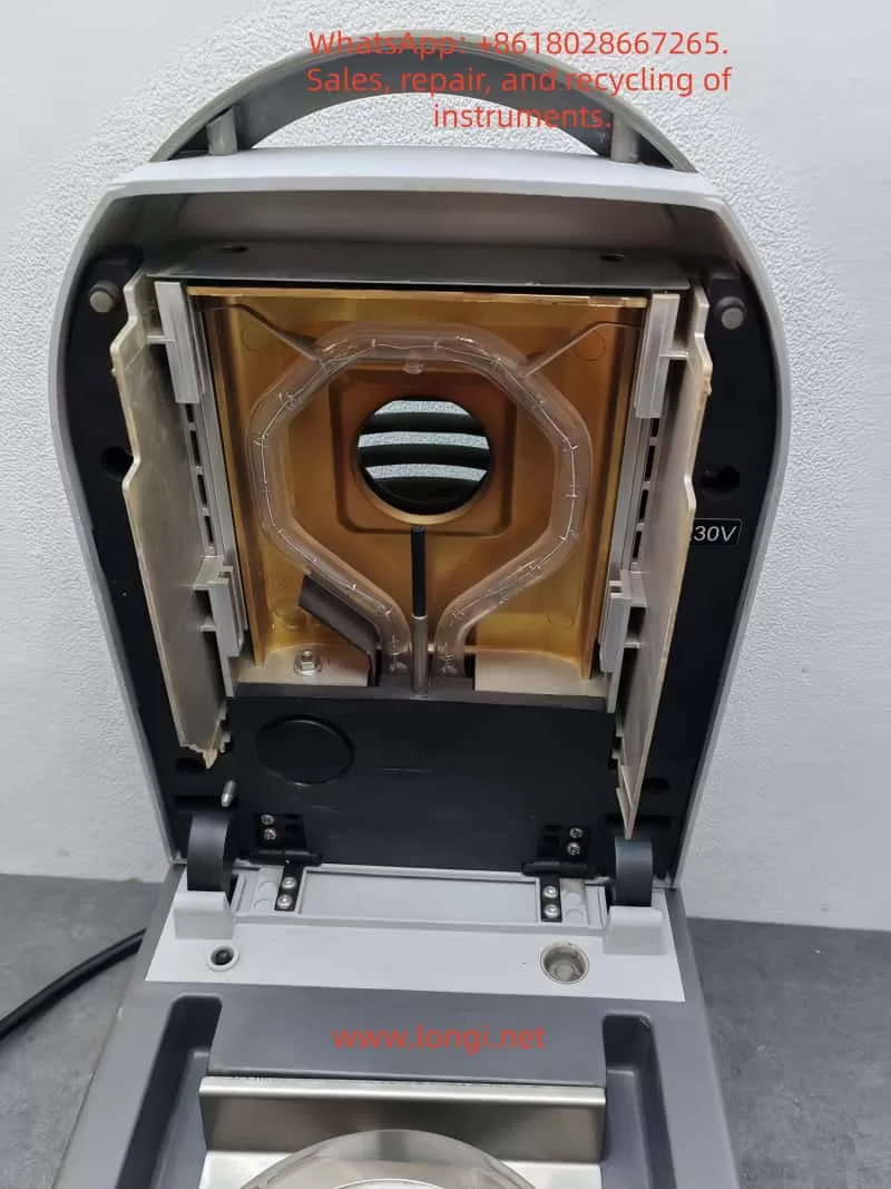
- Heating and Drying: Utilizing a halogen lamp as the heat source, the analyzer generates uniform infrared radiation heating, which is 40% faster than traditional infrared heating. The heating element, designed with a gold-reflective inner chamber, evenly distributes heat to prevent local overheating that could lead to sample decomposition. The temperature can be precisely controlled between 50°C and 200°C, with increments of 1°C.
- Real-Time Monitoring: During the drying process, the instrument continuously monitors changes in the sample’s weight. As moisture evaporates, the weight decreases until a preset shutdown criterion is met (e.g., weight loss rate falls below a threshold).
- Moisture Content Calculation: The moisture percentage (%Moisture) is calculated using the formula: Moisture% = [(Initial Weight – Dried Weight) / Initial Weight] × 100%. Additionally, the analyzer can display %Solids, %Regain, weight in grams, or custom units.
The advantage of this principle lies in its relative measurement approach: it does not require absolute calibration of the sample’s initial weight; only the difference before and after drying is needed to obtain accurate results. This makes the MB45 particularly suitable for handling a wide range of substances, from liquids to solids, and even samples with skin formation or thermal sensitivity. Compared to the traditional oven method, thermogravimetric analysis significantly reduces testing time, typically requiring only minutes rather than hours. Moreover, the built-in software algorithm of the instrument can process complex samples, ensuring high repeatability (0.015% repeatability when using a 10g sample).
In practical applications, the principle also involves heat transfer and volatilization kinetics. The “light-speed heating” characteristic of halogen heating allows the testing area to reach full temperature in less than one minute, with precision heating software gradually controlling the temperature to avoid overshooting. Users can further optimize heating accuracy using an optional temperature calibration kit.
1.2 Instrument Features
As a high-end model in the MB series, the OHAUS MB45 integrates multiple advanced features that set it apart from the competition:
- High-Performance Heating System: The halogen heating element is durable and provides uniform infrared heating. Compared to traditional infrared technology, it starts faster and operates more efficiently. The gold-reflective inner chamber design ensures even heat distribution, reducing testing time and enhancing performance.
- Precision Weighing: With a capacity of 45g and a readability of 0.01%/0.001g, the instrument offers strong repeatability: 0.05% for a 3g sample and 0.015% for a 10g sample. This makes it suitable for high-precision requirements, such as trace moisture determination in the pharmaceutical industry.
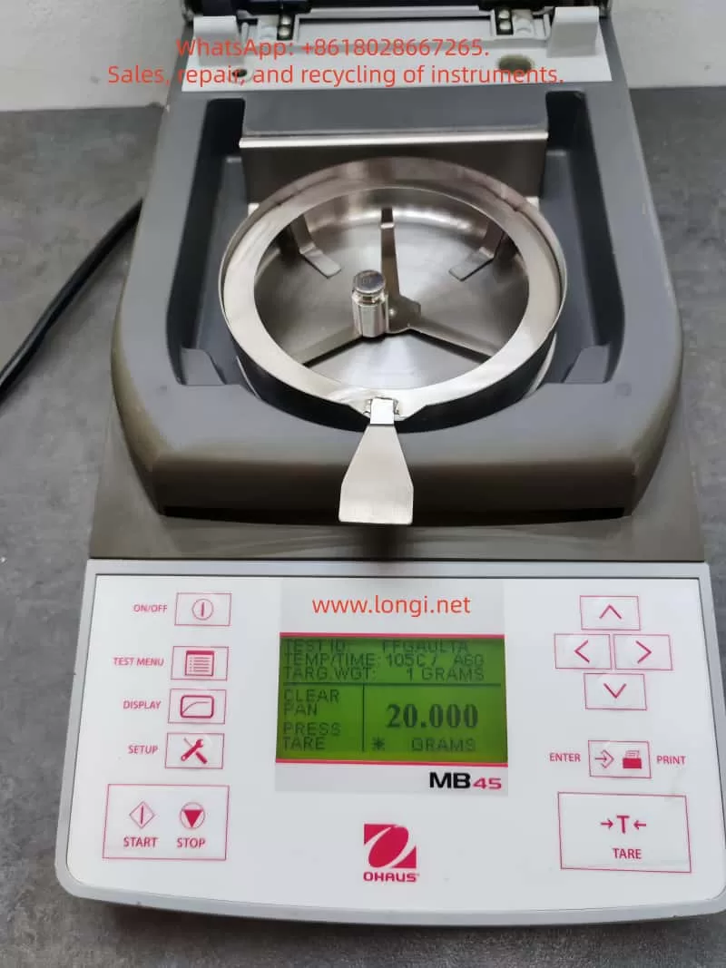
- User-Friendly Interface: Equipped with a 128×64 pixel backlit LCD display, the analyzer supports multiple languages (English, Spanish, French, Italian, German). The display provides rich information, including %Moisture, %Solids, weight, time, temperature, drying curve, and statistical data.
- Powerful Software Functions: The integrated database can store up to 50 drying programs. It supports four automatic drying programs (Fast, Standard, Ramp, Step) for easy one-touch operation. The statistical function automatically calculates standard deviations, making it suitable for quality control. Automatic shutdown options include three pre-programmed endpoints, custom criteria, or timed tests.
- Connectivity and Compliance: The standard RS232 port facilitates connection to printers or computers and supports GLP/GMP format printing. The instrument complies with ISO9001 quality assurance specifications and holds CE, UL, CSA, and FCC certifications.
- Compact Design: Measuring only 19×15.2x36cm and weighing 4.6kg, the analyzer fits well in laboratory spaces with limited room. It operates within a temperature range of 5°C to 40°C.
- Additional Features: Built-in battery backup protects data; multiple display modes can be switched; custom units are supported; a test library allows for storing, editing, and running tests; and statistical data tracking is available.
- Accessory Support: Includes a temperature calibration kit, anti-theft device, sample pan handler, 20g calibration weight, etc. Accessories such as aluminum sample pans (80 pieces) and glass fiber pads (200 pieces) facilitate daily use.
These features make the MB45 suitable not only for pharmaceutical, chemical, and research fields but also for continuous operations in food and beverage, environmental, and quality control applications. Its excellent repeatability and rapid results (up to 40% faster) enhance production efficiency. Compared to the basic model MB35, the MB45 offers a larger sample capacity (45g vs. 35g), a wider temperature range (200°C vs. 160°C), and supports more heating options and test library functions.
In summary, the principles and features of the MB45 embody OHAUS’s traditional qualities: reliability, precision, and user orientation. Through these technologies, users can obtain consistent and accurate results while streamlining operational processes.
2. Installation and Simple Measurement of the Instrument
2.1 Installation Steps
Proper installation is crucial for ensuring the accuracy and safety of the OHAUS MB45 Moisture Analyzer. Below is a detailed installation guide based on the step-by-step instructions in the manual.
- Unpacking and Inspection: Open the packaging and inspect the standard equipment: the instrument body, sample pan handler, 20 aluminum sample pans, glass fiber pads, specimen sample (absorbent glass fiber pad), draft shield components, heat shield, power cord, user manual, and warranty card. Confirm that there is no damage; if any issues are found, contact the dealer.
- Selecting a Location: Place the instrument on a horizontal, stable, and vibration-free workbench. Avoid direct sunlight, heat sources, drafts, or magnetic field interference. The ambient temperature should be between 5°C and 40°C, with moderate humidity. Ensure there is sufficient space at the rear for heat dissipation (at least 10cm). If moved from a cold environment, allow several hours for stabilization.
- Installing the Heat Shield, Draft Shield, and Sample Pan Support: Open the heating chamber cover and place the heat shield (circular metal plate) at the bottom of the chamber. Install the draft shield (plastic ring) to prevent airflow interference. Then, insert the sample pan support (tripod) and ensure stability.
- Leveling the Instrument: Use the front level bubble and adjustable feet to adjust the level. Rotate the feet until the bubble is centered to ensure repeatable results.
- Connecting the Power Supply: Plug the power cord into the socket at the rear of the instrument and connect it to a 120V or 240V AC, 50/60Hz power source. Warning: Use only the original power cord and avoid extension cords. Before the first use, ensure the voltage matches.
- Powering On: Press the On/Off button, and the display will illuminate. After self-testing, the instrument enters the main interface. If stored in a cold environment, allow time for预热 (warm-up) and stabilization.
After installation, it is recommended to perform a preliminary check: close the lid to ensure no abnormal noises; test the balance stability.
2.2 Simple Measurement Steps
After installation, you can proceed with a simple measurement to familiarize yourself with the instrument. Use the provided specimen sample (glass fiber pad) for the test.
- Preparing the Sample: Take approximately 1g of the specimen sample and evenly place it in an aluminum sample pan. Cover it with a glass fiber pad to prevent liquid splashing.
- Entering the Test Menu: Press the Test button to enter the default settings: Test ID as “-DEFAULT-“, temperature at 100°C, and time at 10:00 minutes.
- Placing the Sample: Open the cover and use the sample pan handler to place the sample pan inside. Close the cover to ensure a seal.
- Starting the Measurement: Press the Start/Stop button. The instrument begins heating and weighing. The display shows real-time information such as time, temperature, and moisture%.
- Monitoring the Process: Observe the drying curve. The initial weight is displayed, followed by the current moisture content (e.g., 4.04%) during the process. Press the Display button to switch views: %Moisture, %Solids, weight in grams, etc.
- Ending the Measurement: Once the preset time or shutdown criterion is reached, the instrument automatically stops. A beep sounds to indicate completion. The final result, such as the moisture percentage, is displayed.
- Removing the Sample: Carefully use the handler to remove the hot sample pan to avoid burns. Clean any residue.
This simple measurement typically takes 8-10 minutes. Through this process, users can understand the basic workflow: from sample preparation to result reading. Note: The first measurement may require parameter adjustments to match specific samples.
3. Calibration and Adjustment of the Instrument
3.1 Weight Calibration
Weight calibration ensures the accuracy of the balance. Although not strictly necessary for moisture determination, it is recommended to perform it regularly.
- Preparation: Use a 20g external calibration weight (an optional accessory). Ensure the instrument is level and the sample chamber is empty.
- Entering the Menu: Press the Setup button and select “Weight Calibration.”
- Process: Close the cover and press Enter to begin. When “Place 0g” is displayed, ensure the pan is empty; then, when “Place 20g” is shown, place the calibration weight on the pan. The instrument automatically calibrates and displays success or failure.
- Completion: Press Display to return to the main interface. If calibration fails, check for weight or environmental interference.
After calibration, print a report (if GLP is enabled) to record the date, time, and results.
3.2 Temperature Calibration
Temperature calibration uses an optional temperature calibration kit to ensure heating accuracy.
- Preparation: The kit includes a temperature probe. Allow the instrument to cool for at least 30 minutes.
- Entering the Menu: Navigate to Setup > “Temperature Calibration.”
- Process: Insert the probe and press Enter. The instrument heats to a preset temperature (e.g., 100°C), and the probe reading is compared to the instrument display. Adjust the deviation and press Enter to confirm.
- Multi-Point Calibration: Calibrate multiple temperature points (50-200°C) if needed.
- Completion: The display indicates success. Perform regular calibration (monthly or after frequent use).
3.3 Other Adjustments
- Language Settings: Navigate to Setup > Language to select English or other supported languages.
- Buzzer Volume: Adjust the buzzer volume under Setup > Beeper to Low/High/Off.
- Time and Date: Set the time and date format under Setup > Time-Date.
- Display Contrast and Brightness: Adjust the display visibility under Setup > Adjust Display.
- RS232 Settings: Configure the baud rate, parity, etc., under Setup > RS232.
- Printing and GLP: Enable automatic printing under Setup > Print/GLP.
- Factory Reset: Restore default settings under Setup > Factory Reset.
These adjustments optimize the user experience and ensure the instrument meets specific needs.
4. Operation of the Instrument
4.1 Operation Concepts
The MB45 is operated through the front panel buttons and menus. The main menu includes Setup (settings) and Test (testing). The test menu allows for customizing parameters such as Test ID, drying curve, temperature, shutdown criteria, result display, custom units, target weight, and print interval.
4.2 Entering a Test ID
Press Test > Test ID and input an alphanumeric ID (e.g., sample name).
4.3 Setting the Drying Curve
Choose from Standard (minimal overshoot), Fast (rapid heating), Ramp (controlled slope), or Step (three-step temperature).
4.4 Setting the Drying Temperature
Select a temperature between 50°C and 200°C, with increments of 1°C. Choose a temperature suitable for the sample to avoid decomposition.
4.5 Choosing Shutdown Criteria
- Manual: Press Stop to halt the test.
- Timed: Set a duration between 1 and 120 minutes.
- Automatic: Select A30/A60/A90 (weight loss rate < threshold/second).
- Automatic Free: Customize the weight loss rate.
4.6 Result Display
Choose to display %Moisture, %Solids, %Regain, weight in grams, or custom units.
4.7 Custom Units
Define formulas, such as the moisture/solids ratio.
4.8 Target Weight and Print Interval
Set a target weight prompt; configure the print interval between 1 and 120 seconds.
4.9 Saving and Running Tests
Save up to 50 test programs in the library; run a test by pressing Start.
4.10 Running Mode Display
View real-time curves and statistical data during operation.
4.11 Using the Library
Edit and lock test programs for consistent testing.
When operating the instrument, prioritize safety: wear gloves to avoid burns and optimize sample preparation for the best results.
5. Maintenance and Troubleshooting of the Instrument
5.1 Maintenance
Regular maintenance extends the instrument’s lifespan:
- Cleaning: After disconnecting the power, use a soft cloth to wipe the exterior. Use compressed air to blow dust out of the interior. Avoid introducing liquids.
- Replacing Fuses: Access the fuse box at the rear and replace fuses with the same specifications.
- Resetting Thermal Overload: If heating fails, press the reset button at the rear to restore functionality.
- Storage: Store the instrument in a dry, room-temperature environment.
5.2 Common Faults and Solutions
- Black Display Screen: Check the power supply and fuses; contact service if necessary.
- Prolonged Measurement Time: Adjust the shutdown criteria or drying curve.
- Inaccurate Results: Calibrate the weight and temperature; review sample preparation.
- Error Detection: The display shows error codes; refer to the manual to restart or seek service.
- Other Issues: If there is no weight change in the sample, clean the balance; if overheating occurs, check ventilation.
If issues persist, contact OHAUS service for assistance.
Conclusion
This comprehensive guide equips users with a thorough understanding of the OHAUS MB45 Halogen Moisture Analyzer. Users are encouraged to apply this knowledge in practice and optimize their testing processes for the best results.