1. Introduction
In modern industrial automation, drive safety functions are an indispensable part of system design. In applications where the motor torque must be stopped quickly and reliably, the STO (Safe Torque Off) function plays a crucial role. The ABB MicroFlex e150 servo drive, as a high-performance multi-purpose servo drive, integrates a dual-channel STO safety input circuit that meets international safety standards. Correctly understanding its principle and wiring method is essential not only for the proper operation of the equipment, but also for the safety of personnel and machinery.
This article, based on official documentation and field experience, will analyze in depth the ABB MicroFlex e150’s STO interface design, working principle, and both bench-test and field wiring schemes.
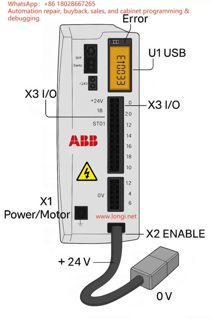
2. Overview of the STO Function
2.1 What is STO?
STO (Safe Torque Off) is a safety function used to immediately cut off the drive pulses to the motor, stopping torque production and preventing unintended motion. Key characteristics:
- Fast response – cuts torque without needing mechanical braking
- No mechanical wear – electronic action, no brake wear
- Safe and reliable – compliant with EN ISO 13849-1 and IEC 61800-5-2 safety standards
In the ABB MicroFlex e150, the STO inputs control the IGBT gate drive enable signals for the power output stage. If the drive detects an STO input open, it will instantly remove gate drive signals and shut down the motor torque.
2.2 Dual-channel redundancy design
The MicroFlex e150 uses a dual-channel STO system:
- STO1: X3:18 (positive) and X3:8 (SREF reference)
- STO2: X3:19 (positive) and X3:9 (SREF reference)
The two channels are fully independent. If either channel is open, the drive enters the STO state. This redundancy improves fault tolerance and allows higher safety integrity levels.
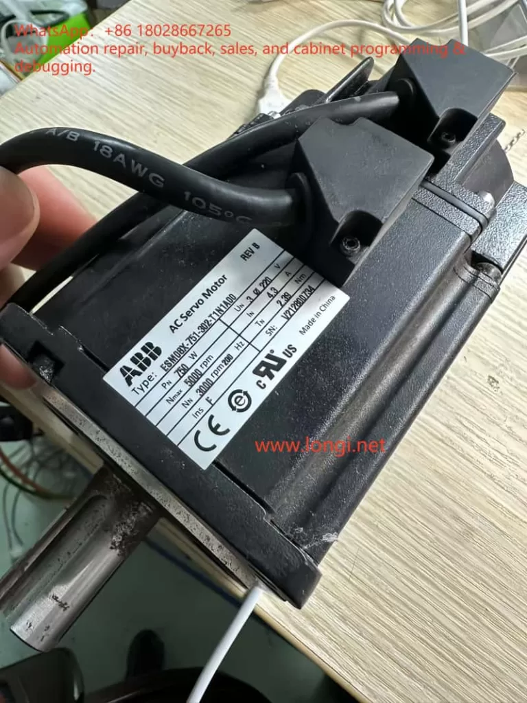
3. Hardware structure and principle
3.1 Interface layout
According to the ABB hardware manual, the X3 connector is a multifunction digital I/O interface. Relevant pins for STO are:
- Pin 18 (STO1 +) – channel 1 positive
- Pin 8 (SREF) – channel 1 reference
- Pin 19 (STO2 +) – channel 2 positive
- Pin 9 (SREF) – channel 2 reference
The drive’s control power input is located on the X2 connector (+24 V and 0 V). This same supply also powers the STO input circuits.
3.2 Internal circuit principle
From the manual’s schematic, each STO input includes:
- A 33 Ω series resistor (current limiting)
- A 6.8 kΩ resistor (biasing)
- An optocoupler (TLP281) for isolation
- Connection to the internal drive ground
When an external 24 V DC is applied between STO+ and SREF, the optocoupler turns on, the channel is detected as “closed,” and the drive is allowed to enable the motor output. If no voltage is present, the drive disables torque output.
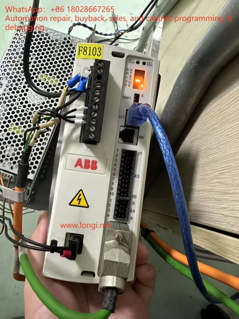
4. E10033 fault cause and clearing method
4.1 Cause of the fault
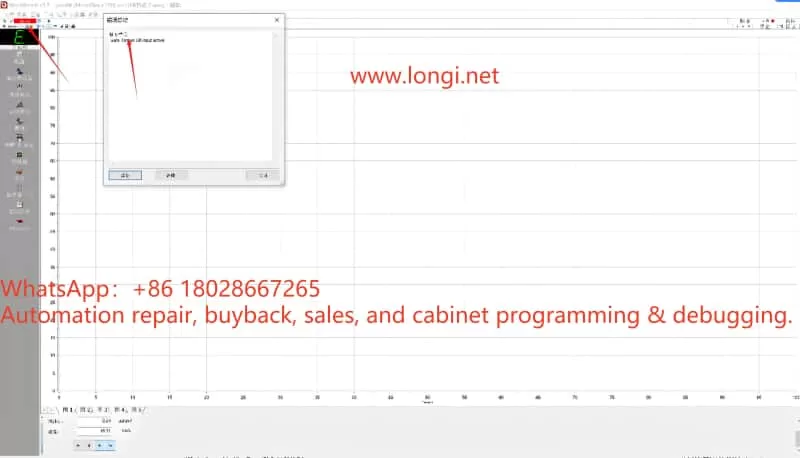
In the manual, E10033 is defined as “Safe Torque Off input active” – in other words, at least one STO channel is open. Typical causes:
- STO inputs not wired (common during bench testing)
- Only one channel wired; the other left floating
- Safety relay or external safety circuit is open
- Wiring error; SREF not properly connected to control 0 V
4.2 Temporary test wiring
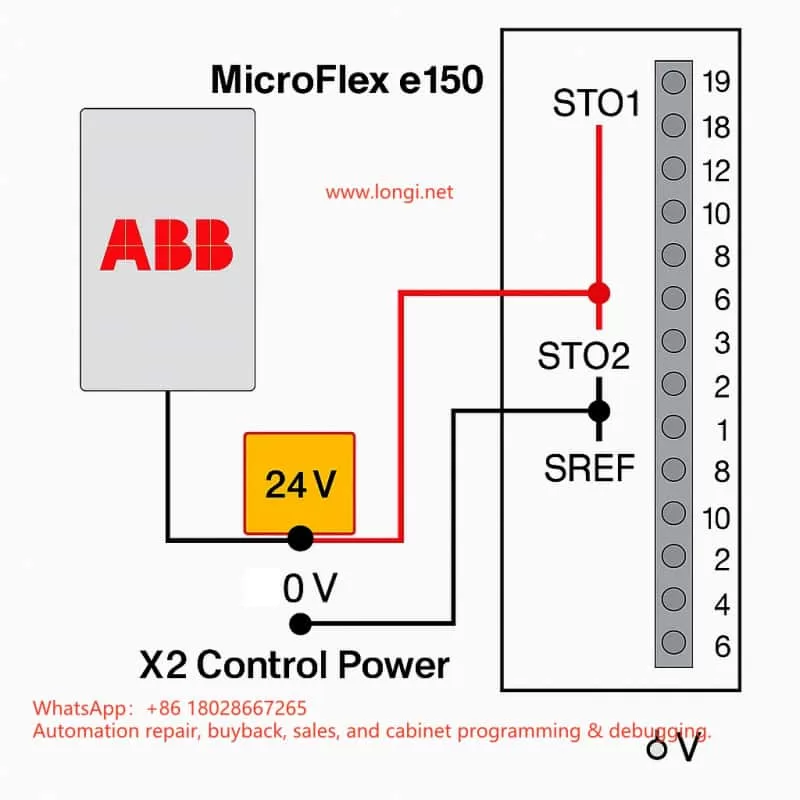
For bench testing or lab environments without a safety circuit, the fault can be cleared by temporary jumpers:
- From X2:+24 V, take two wires to X3:18 (STO1+) and X3:19 (STO2+)
- From X2:0 V, take two wires to X3:8 (SREF) and X3:9 (SREF)
- Both channels now receive 24 V relative to SREF, so the drive sees STO closed
- Power up – the E10033 fault disappears and the drive can be enabled
⚠ This is for testing only. In production systems, a proper safety device must be used.
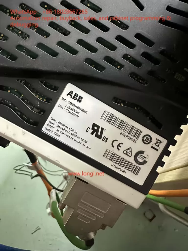
5. Safety wiring in engineering applications
In real installations, the STO channels should be driven by safety-certified control devices such as:
- Dual-channel safety relays (e.g., Pilz PNOZ)
- Safety PLCs (e.g., ABB Pluto, Siemens S7-1500F)
- Emergency stop button + safety relay combinations
5.1 Wiring essentials
- Two independent channels – STO1 and STO2 each controlled by separate contacts of a safety relay
- Common reference – SREF pins must be connected to the control power 0 V
- Shielding & EMC – use twisted shielded pairs for STO signals; ground the shield at one end
5.2 Safety level considerations
According to EN ISO 13849-1, combining dual-channel STO with a safety relay can achieve Performance Level e / SIL3 safety integrity.
Such a setup is widely used in robotic arms, CNC machines, packaging lines, and other equipment needing quick, safe shutdown.
6. Field commissioning tips
- Check STO before first power-on – the drive ships with STO enabled; without wiring, it will always fault E10033.
- Monitor STO status in software – Mint WorkBench allows real-time monitoring of STO channel states to diagnose wiring or circuit issues.
- Test with an external 24 V – during commissioning, a direct 24 V supply can be used to simulate STO closure for verification.
- Avoid overvoltage – STO inputs accept only 24 V DC; applying AC or >30 V DC can damage the optocouplers.
- Do not mix SREF connections – each SREF must be tied correctly to its channel; leaving them floating or mismatched can cause faults.
7. Conclusion
The ABB MicroFlex e150’s STO interface is designed to meet high safety requirements. Dual-channel redundancy ensures that the motor torque can be safely and quickly disabled in critical situations. Whether in a bench test or in a full-scale installation, understanding the STO principle and wiring method is the foundation for both reliable operation and safety compliance.
Key takeaways:
- Both STO channels must be closed to enable the drive
- Bench testing can use temporary jumpers, but production must use a compliant safety circuit
- Proper wiring, shielding, and grounding are vital to avoid nuisance trips
