
1. Introduction: Why Alarm 935 Must Be Treated as Critical
In FANUC CNC systems, 9xx-level alarms are not normal process-related faults. They indicate issues at the core control system level (CPU / memory / system software layer).
Among them:
935 SRAM ECC ERROR is a typical “data integrity collapse” failure.
This type of fault is characterized by:
- CNC may still power on but cannot boot normally
- Loss or corruption of parameters, PMC, or programs
- Repetitive alarm after reboot
- High risk of permanent system data loss if handled incorrectly
For legacy systems such as FANUC 21i-MB, this issue is particularly critical due to reliance on battery-backed SRAM storage.
2. Technical Meaning of Alarm 935
2.1 Role of SRAM in FANUC Systems
In FANUC CNC architecture, memory is divided into:
| Memory Type | Function |
|---|---|
| ROM / FROM | System firmware |
| SRAM | Parameters, PMC logic, NC programs, macro variables |
| Flash (if available) | Extended storage |
In 21i-MB systems:
SRAM is the core working memory that stores all machine-specific logic
2.2 What ECC (Error Correction Code) Means
ECC is a memory integrity mechanism:
- Adds parity/check bits to each data word
- Detects and corrects single-bit errors
- Cannot recover multi-bit or structural corruption
When ECC fails:
The system can no longer guarantee data validity.
2.3 True Meaning of Alarm 935
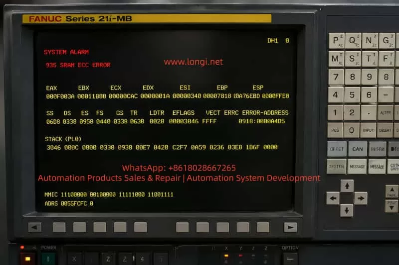
When the system displays:
SYSTEM ALARM 935 SRAM ECC ERROR
It indicates:
- SRAM data structure is corrupted
- ECC correction is no longer possible
- Memory content is considered unreliable
In engineering terms:
❗ The system memory integrity is fundamentally compromised, not just a parameter error.
3. Typical Field Symptoms
3.1 Startup Abnormalities
- CNC stuck during boot process
- Direct entry into SYSTEM ALARM screen
- Unable to access MDI or AUTO modes
3.2 Parameter Loss Symptoms
- Axis parameters missing or zeroed
- PMC not running
- Spindle not enabled
- Homing failure
3.3 Intermittent Behavior
- Temporary normal startup after reboot
- Alarm reappears after operation or power cycle
- Random system instability
4. Root Cause Analysis (Engineering Breakdown)
Alarm 935 is a result-level fault, not a root cause. Common root causes include:
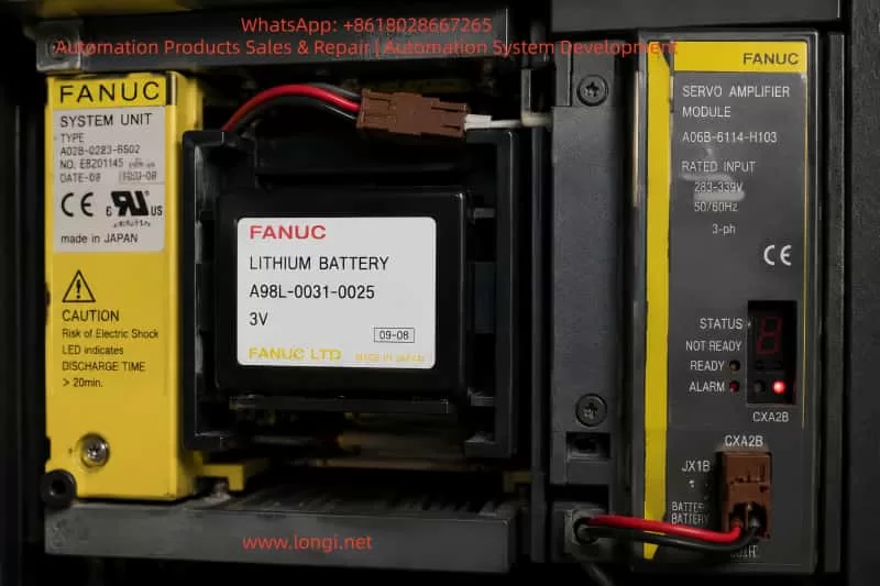
4.1 Battery Failure (Highest Probability)
Mechanism:
SRAM requires battery backup:
- Voltage drop → bit flipping in SRAM
- Long-term undervoltage → memory corruption
- Sudden power loss → incomplete write cycles
Typical conditions:
- Battery not replaced for years
- Machine stored or powered off for long periods
- Loose battery connector
Conclusion:
⭐ This is the most common cause (60%+ cases)
4.2 Abnormal Power Loss / Electrical Noise
Examples:
- Sudden main power shutdown
- Contactor arcing
- Voltage fluctuation
- Poor grounding or lightning surge
This leads to:
SRAM write interruption → partial data corruption → ECC failure
4.3 SRAM / FROM Hardware Damage
Possible failures:
- Aging SRAM chips
- Oxidized contacts
- Board solder joint fatigue
- Internal memory read/write failure
Symptoms:
- Alarm persists after reset
- Immediate reappearance after initialization
- Cannot retain data
4.4 CPU Main Board Failure (Less Common but Severe)
Characteristics:
- Multiple unrelated system alarms
- Random reboot or freeze
- Unstable system behavior
5. Standard Field Repair Procedure
STEP 1: Do NOT Perform Blind Initialization
⚠️ Avoid:
- Memory All Clear without backup
- Random power cycling
- Removing battery during unknown state
Because this may erase:
- PMC ladder logic
- Machine parameters
- Servo tuning data
- Spindle configuration
- Tool changer logic
STEP 2: Check Backup Battery
Procedure:
- Measure battery voltage under load
- Check connector condition
- Inspect corrosion or loose contact
Reference values:
- ≥ 3.0V → OK
- 2.6–2.9V → borderline
- < 2.6V → high risk of failure
STEP 3: Attempt Maintenance Boot Mode
Some FANUC 21i-MB systems support:
- SRAM restore routines
- FROM → SRAM recovery
- Boot-level maintenance menu
If accessible:
Prioritize automatic SRAM restoration before any reset.
STEP 4: SRAM Initialization (Only if Necessary)
Only perform when:
- Backup is available, OR
- Machine can be fully reconfigured
This step:
- Clears corrupted SRAM
- Rebuilds memory structure
STEP 5: System Data Restoration
Required data includes:
- System parameters
- PMC ladder program
- Axis configuration
- Spindle parameters
- Pitch compensation
- Macro variables
STEP 6: Stability Verification
After recovery:
- Check if alarm reappears
- Test after power cycling
- Run machine under load
6. Diagnostic Decision Tree
Case A: Battery replacement + restore → OK
→ Root cause: battery-induced corruption
Case B: Alarm persists after initialization
→ Hardware failure (SRAM / CPU board)
Case C: Intermittent alarm
→ Electrical noise / grounding issue
Case D: Multiple system alarms
→ CPU main board failure
7. Field Failure Mechanism (Real Scenario)
Typical progression:
- Machine experiences power loss or long downtime
- Battery voltage slowly drops
- SRAM integrity degrades gradually
- ECC detects unrecoverable error
- Alarm 935 appears on startup
- Machine becomes non-operational
8. Recovery Challenges and Risks
8.1 Lack of Backup Data (Critical Risk)
Without backup:
- Machine must be fully rebuilt
- All CNC logic must be re-entered manually
- Servo tuning and spindle parameters must be reconfigured
8.2 Secondary Damage Risk
Incorrect handling may cause:
- Permanent data loss after memory clear
- PMC download failure
- Axis motion errors
- System lock-up
9. Preventive Maintenance Strategy
9.1 Battery Management
- Replace every 12–18 months
- Do not wait for low battery alarm
- Keep spare batteries available
9.2 Power Quality Protection
- Install UPS for CNC system
- Add surge suppression for contactors
- Ensure proper grounding system
9.3 Regular Data Backup
Must include:
- Full system backup
- PMC ladder program
- Parameter files
10. Conclusion
The FANUC 21i-MB Alarm 935 (SRAM ECC ERROR) is not a simple parameter issue but a system-level memory integrity failure.
Its core meaning is:
The CNC’s internal working memory has become unreliable or corrupted.
Key engineering principle:
Repair priority is not “resetting the machine”, but preserving data first.
One-line summary:
Alarm 935 means the CNC has lost trust in its own memory system — recovery depends entirely on backup availability.