
Keypad Operation · Factory Reset · Pulse Position Control · Fault Codes & Troubleshooting
The Nidec Commander C200 C300 manual is an essential technical reference for engineers and maintenance professionals working with Commander C200 and C300 AC drives in industrial automation systems.
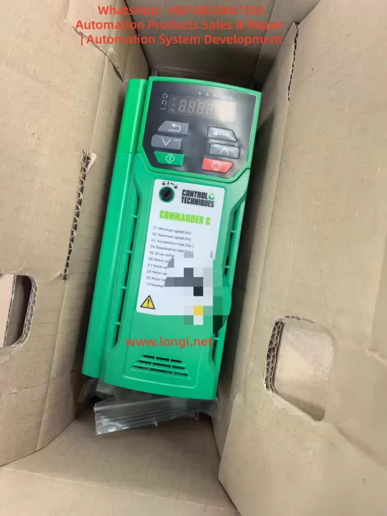
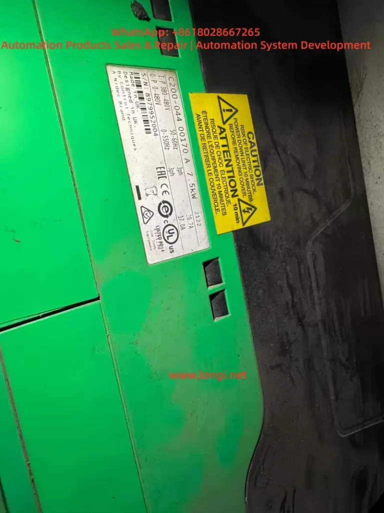
The Nidec Control Techniques Commander C200 and C300 series AC drives are high-performance general-purpose variable frequency drives widely used in industrial automation, machine tools, conveyors, pumps, fans, packaging machines, and light positioning applications.
The Commander series is known for its flexible I/O configuration, reliable open-loop vector control, advanced diagnostics, and (on C300 models) integrated Safe Torque Off (STO) safety functionality. When correctly configured, these drives can not only perform traditional speed control, but also support pulse-based motion and positioning applications.
This technical guide is written for engineers, technicians, and maintenance professionals. It focuses on the most important practical topics:
- Commander C200/C300 keypad and operating panel functions
- How to restore factory default parameters
- How to set and remove passwords and access levels
- How to implement pulse-based forward/reverse position control
- Control terminal wiring logic
- Core parameter configuration concepts
- Common fault codes and professional troubleshooting methods
This is not a simple manual translation, but a structured engineering guide based on real-world field application and maintenance practice.
1. Overview of Nidec Commander C200 / C300 Drives
This Nidec Commander C200 C300 manual is designed to help users understand configuration, diagnostics, and real industrial applications.
The Commander C200 and C300 are part of the Nidec Control Techniques Commander platform, positioned between compact micro-drives and high-end servo or regenerative drives.
Key technical highlights include:
- Open-loop vector control, V/F control, and RFC-A mode
- Wide motor compatibility for standard induction motors
- Flexible digital and analog I/O configuration
- High-speed frequency and pulse input capability
- Built-in relay outputs and analog monitoring outputs
- Support for Modbus RTU and optional fieldbus modules
- NV Media Card support for parameter cloning
- Integrated STO safety inputs on C300 models
- Powerful diagnostics and internal status monitoring
From an engineering perspective, Commander C200 is mainly aimed at standard industrial applications, while Commander C300 is designed for more demanding systems requiring functional safety, system integration, or advanced logic.
2. Commander C200 / C300 Keypad and Operating Panel Guide
The local keypad is the main human-machine interface for the Commander drive. It allows technicians to monitor operating states, modify parameters, start and stop the drive, and reset faults.
2.1 Keypad Button Functions
The standard Commander keypad includes:
- ESC – Exit, cancel, or return
- UP / DOWN arrows – Navigate menus and adjust values
- ENTER – Confirm or access a parameter
- RUN (green) – Local run command
- STOP / RESET (red) – Stop motor and reset trips
- Forward indicator LED
- Reverse indicator LED
- Local reference indicator
The display shows:
- Output frequency
- Motor current
- DC bus voltage
- Drive status
- Active fault or alarm codes
- Parameter numbers and values
In maintenance work, the keypad is also the most important diagnostic tool, allowing access to fault history, I/O monitoring, and internal operating data.
2.2 Parameter Menu Structure
Commander drives use a structured menu system:
- Menu 0 – Quick start and essential parameters
- Menu 1–6 – References, ramps, control, torque, and logic
- Menu 7 – Analog inputs and outputs
- Menu 8 – Digital inputs and outputs
- Menu 9 – Logic functions, timers, and internal blocks
- Menu 10 – Status, monitoring, and fault diagnostics
- Menu 11 – General system configuration
- Menu 18 / 20 – Application menus
In real-world commissioning and repair, most work is done in:
- Menu 0 (motor and control basics)
- Menu 7 (analog signal configuration)
- Menu 8 (digital terminal mapping)
- Menu 10 (faults and internal status)
Understanding this menu structure significantly improves troubleshooting efficiency.
3. Restoring Factory Defaults and Parameter Initialization
3.1 Why Factory Reset Is Important
Restoring factory parameters is essential in situations such as:
- Second-hand drives with unknown configuration
- After major faults or memory errors
- Before converting the drive to a new application
- When troubleshooting unpredictable behavior
Factory reset clears:
- Motor data
- Terminal assignments
- Control sources
- Application logic
- Safety or password settings
After reset, the drive returns to its original state and must be recommissioned.
3.2 Factory Reset Procedure
Typical procedure:
- Ensure the drive is stopped and safe.
- Enter the parameter menu.
- Locate the “Restore Defaults” or “Factory Reset” function.
- Execute the reset.
- Power the drive off and on.
After reset, always re-enter the essential motor parameters:
- Motor rated voltage
- Motor rated current
- Motor rated frequency
- Motor speed (RPM)
- Control mode
Failure to do this often causes overcurrent trips, unstable operation, or torque loss.
3.3 Password and Access Level System
Commander drives support multi-level parameter access:
- Operator level
- Engineer level
- Advanced or protected level
Passwords can be configured to:
- Lock critical parameters
- Prevent unauthorized changes
- Protect machine tuning
- Control service access
Once activated, only users with the correct password can modify restricted parameters.
3.4 Removing or Recovering a Forgotten Password
This is a very common maintenance problem.
Professional recovery methods include:
- Factory parameter restoration
- Parameter overwrite via NV Media Card
- Manufacturer service reset procedures
In most industrial service scenarios, the most reliable solution is:
Factory reset + full recommissioning
This guarantees stable operation and removes hidden logic or unsafe settings.
4. Pulse-Based Forward/Reverse Position Control with Commander Drives
Although the Commander C200 and C300 are not servo drives, they support high-speed frequency and pulse input functions. This makes them suitable for:
- Simple positioning systems
- Length control
- Pulse speed reference systems
- PLC-controlled motion
- Stepper motor replacement projects
4.1 Control Principle
A typical pulse control structure is:
- PLC or controller outputs pulse train
- Commander drive reads pulses as frequency or position reference
- Direction signal defines forward or reverse rotation
- Run/Enable signals start or stop the drive
- Internal ramp and scaling parameters define motor behavior
In this structure:
- Pulse frequency = speed or movement rate
- Pulse count = displacement
- Direction input = forward / reverse
- Enable input = safety or start control
4.2 Terminal Wiring Concept
Although terminal numbers differ by frame size, the typical wiring logic is:
- 0V common
- +24V user supply
- High-speed input terminal → Pulse signal
- Digital input → Direction
- Digital input → Run/Stop
- Enable or STO → Drive enable
Common engineering practices:
- Use shielded twisted pair cable for pulses
- Keep signal wiring away from motor cables
- Ensure proper grounding
- Verify signal voltage compatibility
Pulse input types typically supported:
- Open collector
- Push-pull
- Frequency signal
4.3 Core Parameter Configuration Logic
Successful pulse control depends on four parameter groups:
4.3.1 Operating Mode
Select a suitable mode such as:
- Open-loop vector
- RFC-A
Then assign the speed reference source to an external or pulse input.
4.3.2 Reference Source Assignment
Configure:
- Pulse or frequency input as main reference
- Scaling parameters
- Filtering time constants
This tells the drive to treat pulses as the main speed or position signal.
4.3.3 Pulse Scaling
Critical settings include:
- Pulses per revolution
- Pulses per Hz
- Maximum input frequency
- Speed conversion ratio
Example:
If 1000 pulses = 50 Hz
Then 1 Hz = 20 pulses
Correct scaling ensures predictable motion.
4.3.4 Direction and Run Control
Digital inputs are assigned to:
- Run forward
- Run reverse
- Direction control
- Drive enable
This configuration allows the PLC or controller to command motion precisely.
4.4 Typical Applications
Commander pulse control is commonly used for:
- Conveyor length control
- Packaging feed systems
- Simple screw drives
- Coil winding machines
- Small lifting or indexing systems
It is ideal for applications that do not require high-precision servo loops but demand reliable synchronized motion.
5. Commander C200 / C300 Fault Codes and Troubleshooting Guide
Commander drives include a comprehensive diagnostic system. Faults are generally grouped into:
- Power supply faults
- Motor and load faults
- Control faults
- Safety or enable faults
- Hardware faults
5.1 Overcurrent Trips
Typical messages:
- Overcurrent
- Instantaneous overcurrent
Common causes:
- Motor phase short circuit
- Output cable damage
- IGBT module failure
- Incorrect motor parameters
- Mechanical overload
Professional checks:
- Measure U/V/W to ground
- Insulation test motor
- Check power module
- Increase acceleration time
- Verify motor nameplate data
5.2 Overvoltage Trips
Typical messages:
- DC bus overvoltage
Causes:
- Rapid deceleration
- Regenerative energy
- Faulty braking resistor
- High supply voltage
Solutions:
- Install braking resistor
- Increase deceleration time
- Check braking circuit
- Test DC bus capacitors
5.3 Undervoltage Trips
Causes:
- Input phase loss
- Rectifier failure
- Weak power supply
- Aging capacitors
Troubleshooting:
- Measure three-phase input
- Check rectifier bridge
- Inspect charging resistors
- Measure DC bus ripple
5.4 Overtemperature Trips
Triggers include:
- Drive overheating
- IGBT thermal alarms
- Motor thermal input
Checkpoints:
- Cooling fans
- Heatsink contamination
- Load conditions
- Ambient temperature
- Thermal sensor wiring
5.5 Speed or Control Model Faults
Often related to:
- Incorrect motor parameters
- Unstable loads
- Signal noise
- Control mode mismatch
Actions:
- Re-enter motor data
- Check grounding and shielding
- Verify feedback or RFC settings
- Reduce electrical noise
5.6 STO and Enable Faults (C300)
Typical symptoms:
- Drive cannot start
- STO active
- Drive inhibited
Inspection:
- 24 V supply on STO channels
- Dual-channel consistency
- Safety relay logic
- Wiring integrity
Many “no run” service calls are caused by STO miswiring rather than drive failure.
5.7 Hardware and Internal Faults
Such faults often indicate:
- Power board damage
- Control board faults
- EEPROM corruption
- Gate driver failure
These typically require:
- Professional board-level repair
- Replacement modules
- Factory service intervention
6. Engineering Recommendations
- Always back up parameters before modification
- After repairs, perform a full factory reset
- Verify pulse signals with an oscilloscope
- Enter real motor nameplate data
- Ensure high-quality grounding
- Keep signal and power wiring separated
- Investigate power quality issues early
7. Conclusion
The Nidec Commander C200 and C300 series drives provide a powerful, flexible, and reliable solution for a wide range of industrial automation tasks. With correct configuration, they can perform not only standard variable speed control, but also pulse-based motion control, logic integration, and safety-critical operation.
With this Nidec Commander C200 C300 manual, engineers can significantly reduce downtime and improve commissioning efficiency.
Understanding keypad operation, parameter logic, terminal mapping, and fault diagnostics is essential for successful commissioning and long-term system reliability.
Frequently Asked Questions about Nidec Commander C200 C300 Manual
Q1. What is the Nidec Commander C200 C300 manual used for?
Q2. Does the Commander C300 support pulse position control?
Q3. How can I reset a Commander C200 drive to factory settings?