
Introduction
The ABB ACH580 series of inverters are low-voltage AC drive devices specifically designed for heating, ventilation, and air conditioning (HVAC) applications. They are renowned for their high efficiency, reliability, and user-friendly interfaces. This series is suitable for controlling asynchronous induction motors, permanent magnet motors, and synchronous reluctance motors, supporting a power range from 0.75 kW to 250 kW and voltage levels covering 208-480 V.
One of the core functions of the ACH580 is the motor identification run (ID Run), an automatic tuning process that precisely measures motor parameters to ensure a perfect match between the inverter and the motor, thereby achieving optimal performance, energy efficiency, and protection.
However, in practical applications, motor ID run faults are one of the common issues. Typical faults include FF86 (ID Run Failed) and AFF6 (Identification Run Warning). These faults can result in the motor failing to start, operating inefficiently, or causing equipment damage. According to ABB’s official manuals and technical notes, these problems often stem from improper parameter settings, mechanical constraints, or external interference. The FF86 fault is usually accompanied by auxiliary codes, such as 0000 0003, indicating that the maximum torque limit is too low.
This article will comprehensively elaborate on the ID run principles, fault analysis, diagnosis, and repair methods of the ACH580 inverter, drawing on ABB’s official documents, fault diagnosis guides, and best practices. It will also provide installation and maintenance recommendations to help engineers and maintenance personnel efficiently resolve issues.
By reading this article, you will learn how to avoid these faults and ensure stable system operation. The content is based on ABB’s firmware manuals (version 2.15 and above) and real-world cases, ensuring originality and practicality.
ACH580 Inverter Overview
The ACH580 series is a dedicated HVAC model within ABB’s low-voltage general-purpose drive product line, emphasizing energy efficiency, ease of use, and compatibility. Its main features include:
- Harmonic Suppression: Built-in active filters reduce harmonic distortion, with a total harmonic distortion (THDi) of less than 5%, complying with IEEE 519 standards and improving grid quality.
- Control Modes: Supports scalar control and vector control, suitable for constant torque and fan/pump loads. Vector mode requires an ID run to optimize torque control.
- Communication Interfaces: Integrated Modbus RTU, supporting BACnet MS/TP, LonWorks, and other HVAC protocols for easy building automation integration.
- Safety Features: Built-in Safe Torque Off (STO), complying with SIL 3/PL e standards; supports emergency stops and external event inputs.
- Technical Specifications: Input voltage of 208-240 V or 380-480 V; output frequency of 0-500 Hz; protection class IP21/IP55; ambient temperature range of -15°C to 50°C (no derating). The power module uses IGBT technology, achieving an efficiency of up to 98%.
The ACH580 is suitable for HVAC equipment such as fans, pumps, and compressors, significantly reducing energy consumption (saving 30-50% compared to direct starting). Its control panel (ACH-AP-H) provides an intuitive menu, supporting multiple languages and an assistant mode for quick startup. However, ID run faults are prone to occur during initial configuration or after parameter changes, requiring a systematic understanding.
Motor ID Run Principles
The motor ID run is a crucial function of the ACH580 inverter, used to automatically identify the electrical parameters of the motor, such as resistance, inductance, and magnetization current. These parameters are used to build a motor model, ensuring precise speed, torque, and flux control. The ID run is divided into two modes:
- Normal ID Run: Rotating mode. The inverter applies a variable frequency signal to rotate the motor shaft (without load) and measures the dynamic response. Suitable for most applications, it lasts 1-2 minutes and provides the highest precision. However, it requires ensuring that the motor shaft can rotate freely; otherwise, a fault will occur.
- Standstill ID Run: Stationary mode. Only the motor stator is magnetized, and the shaft does not rotate. Suitable for scenarios where the load cannot be removed, such as when a fan impeller is connected. The precision is slightly lower, but it is safer.
The triggering conditions for an ID run include:
- Initial startup.
- Changes to parameter group 99 (motor data), such as rated current (99.06), voltage (99.07), frequency (99.08), speed (99.09), power (99.10), and torque (99.12).
- After a firmware upgrade or factory reset.
The process is as follows:
- Set parameter 99.13 (ID Run Requested) to the desired mode.
- Start the inverter in local mode (Hand).
- The inverter injects test signals and calculates parameters.
- If successful, the internal model is updated; if failed, FF86 is triggered.
The ID run improves performance by enhancing low-speed torque (up to 200% of rated torque) and reducing vibration and noise. Systems that have not undergone an ID run may experience overcurrent, stalling, or low efficiency.
Common Fault Analysis
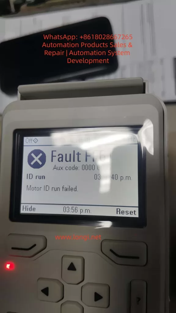
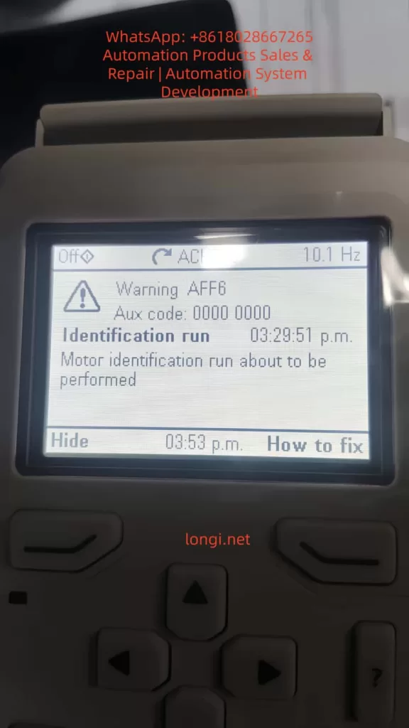
The main ID run-related faults in the ACH580 are FF86 and AFF6.
- FF86 (ID Run Failed): Indicates that the ID run was not successfully completed. The auxiliary code provides details:
- 0000 0001: The maximum current limit is too low (parameter 30.17 < 99.06).
- 0000 0002: The maximum speed or field weakening point is too low (check 30.11/30.12 with 99.09).
- 0000 0003: The maximum torque limit is too low (30.20 < 100% of rated torque).
- 0000 0012: The motor is too large (the drive size does not match).
- Others: Incorrect motor data or external interference.
This fault stops the motor and requires a reset and repair.
- AFF6 (Identification Run Warning): An informational warning indicating that an ID run will be automatically performed at the next startup. Not a serious error, but ignoring it may affect performance. Common after parameter changes.
These faults are common in HVAC systems and affect the continuous operation of fans or pumps. According to ABB Technical Note 143, the failure rate can reach 10-20%, mostly due to human configuration errors.
Detailed Fault Causes
The reasons for ID run failures are diverse and can be classified into parameter, mechanical, electrical, and external factors.
- Improper Parameter Settings (Most Common, Accounting for Over 50%):
- Incorrect motor nameplate data entry: Rated values do not match the actual values, leading to calculation deviations.
- Overly conservative limit parameters: For example, a torque upper limit (30.20) lower than 100% prevents the inverter from applying sufficient excitation signals.
- Mismatched control modes: Vector mode requires an ID run but is not enabled.
- Mechanical Constraints:
- The motor shaft is not free: Load connection, brake locking, or bearing seizure. In Normal mode, the shaft must be able to rotate at least a few turns.
- Mechanical resonance: Vibration interference in high-load applications affects measurements.
- Electrical Issues:
- Wiring errors: Reversed phase sequence, loose connections, or insulation faults cause current imbalances.
- Ground faults: Motor or cable grounding triggers A2B3 (ground leakage) related alarms.
- Power supply fluctuations: Low voltage (<0.66 × rated voltage) affects magnetization.
- External Interference:
- PLC or fieldbus control: External signals interrupt the ID process.
- Environmental factors: High temperatures (>50°C) or dust trigger overheating protection activation.
- Drive hardware: IGBT failures or control board power supply issues (check 95.04).
According to search results, auxiliary code 0003 often occurs when the torque setting is too low (<150% of the recommended value), especially after replacing a new motor.
Diagnostic Steps
Diagnosis requires a systematic approach using the control panel and tools.
- View Fault Display: The panel displays FF86/AFF6 and auxiliary codes. Press “How to Fix” for suggestions.
- Check Event Log (Parameter Group 04):
- Records the time, code, and parameter status of recent faults.
- For example, 04.01 displays active faults, and 04.11-04.15 display historical records.
- Parameter Verification:
- Group 99: Compare with the motor nameplate to ensure accuracy.
- Group 30: Check limit values (30.11 minimum speed, 30.12 maximum speed, 30.17 maximum current, 30.20 maximum torque).
- Group 96: System settings, such as 96.06 parameter recovery.
- Electrical Testing:
- Use a multimeter to measure motor insulation resistance (>1 MΩ) and continuity.
- Check cable phase sequence (U-V-W corresponds to T1-T2-T3).
- Measure input voltage stability.
- Isolation Testing:
- Disconnect external control (PLC) and test in local mode.
- Remove the load and attempt an ID run.
- If the panel is unavailable, use the Drive Composer PC tool to connect and view detailed logs.
Repair Methods
Repairs should be carried out in sequence, ensuring safety (power off, lockout/tagout).
- Basic Restart:
- Power off for 5-10 minutes and restart the inverter. Clears temporary faults.
- Adjust Torque and Limits (for 0003 code):
- Set 30.20 to 150-200%.
- Ensure 30.17 > 99.06 and 30.12 > 0.55 × 99.09.
- Verify Motor Data:
- Enter nameplate values: current, voltage, frequency, speed, power, and torque.
- If changed, trigger AFF6 and manually run the ID.
- Ensure Shaft Freedom:
- Disconnect the load and release the brake.
- Check bearings and couplings.
- Disable External Control:
- Disconnect DI/DO and fieldbus.
- Set 20.12 Run Enable to local.
- Manual ID Run:
- Set 99.13 to Normal or Standstill.
- Start locally and monitor progress.
- After success, reset the fault (96.08 or panel Reset).
- Restore Factory Settings:
- Method 1: Menu > Primary Settings > Reset to Defaults > Reset All to Factory Defaults.
- Method 2: Set parameter 96.06 to 34560.
- After resetting, re-enter group 99 data and back up parameters (96.07).
- Advanced Repairs:
- If the issue persists, check hardware: replace cables and test motor windings.
- Contact ABB support, providing the model, serial number, and firmware version.
- After repair, verify: Run a no-load test and monitor current and speed.
Installation Best Practices
Correct installation reduces ID run faults.
- Location Selection:
- Install in a well-ventilated, dry, and dust-free environment. Avoid direct sunlight and vibration sources.
- Maintain spacing: 200 mm on the top/bottom and 100 mm on the sides to ensure airflow.
- Electrical Installation:
- Use shielded cables and ensure good grounding. Separate input/output cables to reduce EMI.
- Power cables: Copper core, cross-sectional area matching power (e.g., 6 mm² for 10 kW).
- Control cables: Shielded twisted pair, with signal lines isolated from power lines by >30 cm.
- Grounding Requirements:
- Dual PE conductors: One main and one auxiliary, with a cross-sectional area of ≥10 mm² Cu.
- Avoid ground loops and ensure the motor and inverter share the same ground.
- Initial Startup:
- Disconnect the load before entering motor data.
- Verify safety circuits (STO, emergency stop).
- Follow IEC/EN 61800-5-1 standards and check insulation after installation.
Maintenance Best Practices
Regular maintenance extends lifespan and prevents faults.
- Cleaning:
- Vacuum the panel and fan monthly to avoid using compressed air for dust removal.
- Clean the radiator annually to ensure it is dust-free.
- Inspection:
- Check connections quarterly for tightness, with a torque of 5-10 Nm.
- Monitor temperature (<50°C), vibration, and noise.
- Test the STO function: Disconnect during operation to confirm the motor stops.
- Parameter Backup:
- Regularly back up parameters using Drive Composer.
- Check for firmware updates on the ABB website and ensure compatibility.
- Preventive Testing:
- Perform an ID run calibration annually, especially after motor replacement.
- Monitor energy consumption and efficiency, and diagnose anomalies.
- Environmental Control:
- Maintain humidity <95% without condensation and stable temperature.
- Install in a NEMA 12 enclosure for dust protection.
- Keep a maintenance log for tracking.
Case Studies
- Case 1: In an HVAC system of a commercial building, an ACH580 drove a fan. After initial installation, FF86 (0003 code) occurred. Diagnosis: The torque limit 30.20 was set to 80%. Repair: Adjusted to 150% and manually ran the ID run successfully. Result: Efficiency improved by 15%.
- Case 2: In an industrial pump station, AFF6 recurred. Cause: PLC interference. Repair: Isolated control and reset parameters. Prevention: Added a filter.
- Case 3: Based on search results, a paper mill using an ACH580 experienced ID failures due to an oversized motor. Solution: Upgraded the drive size.
These cases emphasize the importance of parameter accuracy and isolation.
Preventive Measures
- Initial Configuration: Strictly enter data according to the nameplate and select the appropriate ID mode.
- Training: Ensure operators understand the panel and fault codes.
- Monitoring System: Integrate remote diagnostics for early warnings.
- Spare Parts Preparation: Keep cables and modules in stock.
- Compliance: Follow ABB guidelines and avoid non-original accessories.
Conclusion
The motor ID run of the ABB ACH580 inverter is crucial for ensuring efficient operation, but faults such as FF86 and AFF6 require prompt handling. By understanding the principles, analyzing causes, conducting systematic diagnosis and repair, system reliability can be maximized. Combining installation and maintenance best practices, the ACH580 can provide long-term stable performance, reducing energy consumption and downtime risks. It is recommended to regularly refer to ABB manuals and technical support to adapt to specific applications. Correct implementation not only resolves issues but also optimizes the overall HVAC system.