
Abstract
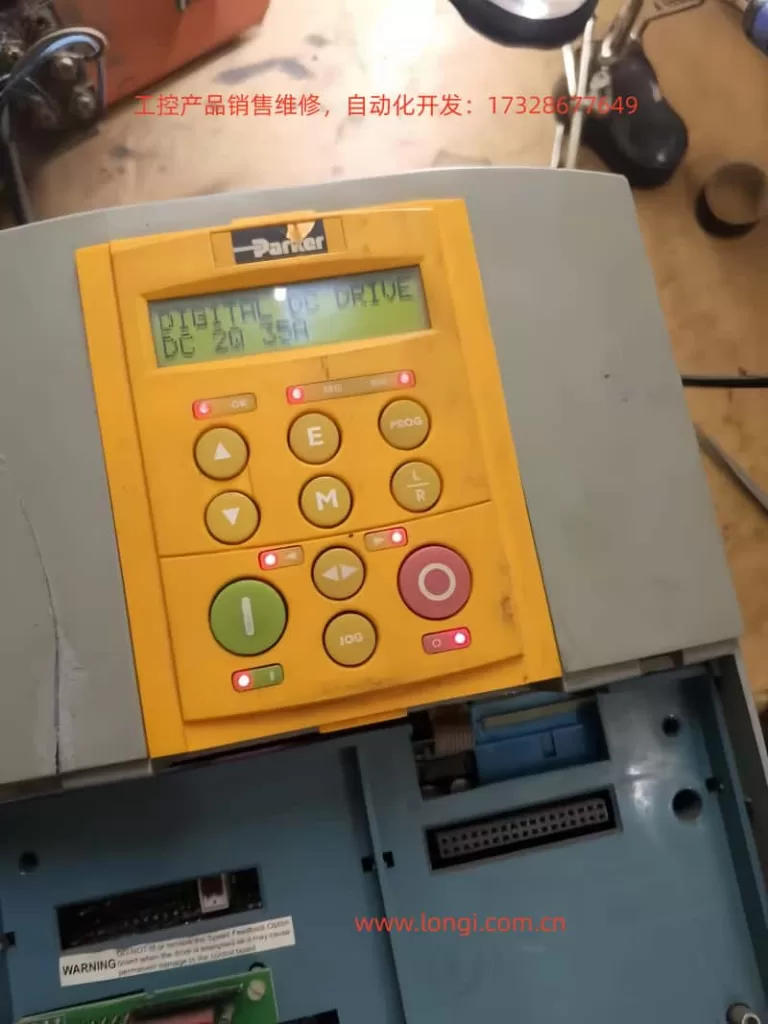
The Parker 590 Digital DC Drive is a widely used high-performance DC speed controller applied in rolling mills, extrusion lines, wire drawing machines, paper production, printing equipment, and chemical process systems.
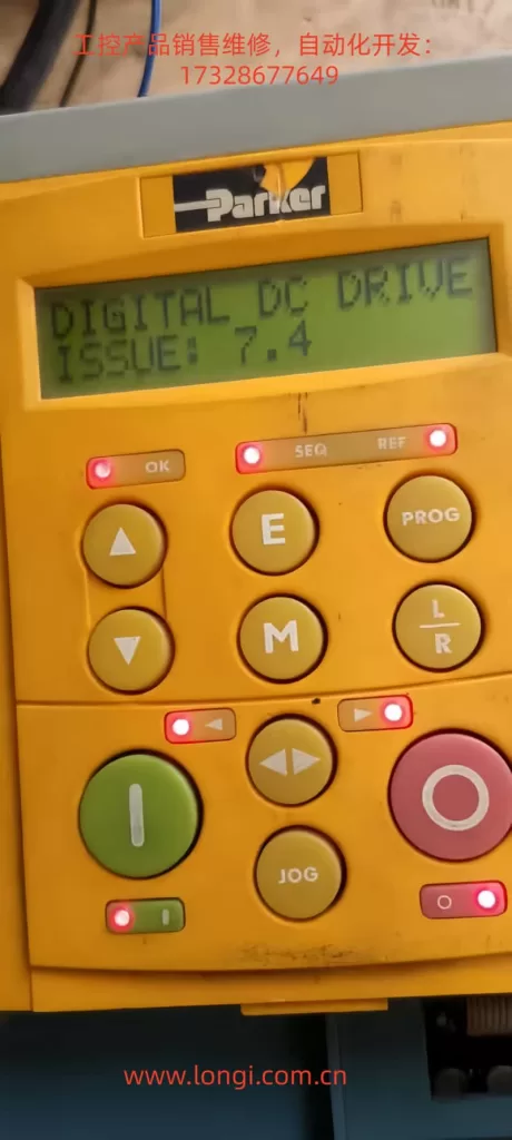
A frequently misunderstood fault condition encountered in field service is the following: immediately after power-up, all LEDs on the keypad flash simultaneously, and the display shows “DIGITAL DC DRIVE – ISSUE x.x”. The drive does not enter normal operation or parameter menus.
This condition is often incorrectly treated as a parameter problem, accidental calibration mode, or software issue. In reality, it almost always indicates an internal startup failure of the control system.
This paper provides a system-level engineering explanation of this phenomenon, analyzes its root causes, and proposes a structured troubleshooting and repair methodology suitable for industrial maintenance professionals.
1. System Architecture and Startup Logic of the Parker 590
To correctly understand the “ISSUE + all LEDs flashing” condition, it is essential to first review the internal architecture of the Parker 590.
From a system perspective, a Parker 590 DC drive consists of the following major functional blocks:
- Control Power Supply (SMPS)
Generates regulated low-voltage rails such as +5 V, ±15 V, and +24 V for logic and analog circuits. - Main Control System (MCU/DSP/CPLD)
Executes firmware responsible for self-tests, parameter management, communications, control algorithms, and protection logic. - Human-Machine Interface (HMI)
Keypad, LEDs, and LCD module communicating with the main controller. - Power and Firing System
Gate drive circuits, armature and field control, SCR or transistor trigger boards. - Measurement and Protection Circuits
Voltage/current sensing, isolation, hardware protection channels.
The normal startup sequence of the Parker 590 is:
- Control power supply starts
- Logic voltages stabilize
- Reset is released
- Clock oscillation established
- Boot code executed
- Internal hardware self-test
- Parameter memory verification
- Power section status check
- Transition to READY/STOP state
If any critical stage fails, the drive will not enter normal operating mode.
2. Engineering Meaning of “All LEDs Flashing + ISSUE”
In Parker 590 terminology, “ISSUE” is not a user fault code (such as overcurrent or overvoltage). It is an internal startup diagnostic indication.
It means:
The drive failed to complete its initialization and self-test sequence and did not reach a valid operational state.
Typical characteristics of this condition include:
- All keypad LEDs flashing synchronously
- Display fixed on “ISSUE x.x”
- Inability to enter standard menus
- Weak or absent keypad response
- State remaining unchanged or repeatedly resetting
This is fundamentally a boot or initialization failure, not an application or parameter fault.
At this stage, the controller is not fully running and cannot reliably execute parameter handling, calibration routines, or normal control logic.
3. Distinction from Calibration or Engineering Modes
Parker 590 drives do have special engineering or calibration modes that may involve unusual LED behavior. These are sometimes confused with the ISSUE condition.
However, there are decisive differences.
3.1 Characteristics of Calibration / Engineering Modes
- Clear menu or calibration item displayed
- Keys respond normally
- Structured menu navigation
- No “ISSUE” indication
- System already fully operational
These modes require the CPU, memory, and power rails to be fully functional.
3.2 Characteristics of Startup Failure Mode
- Appears immediately at power-up
- Not triggered intentionally
- Display shows “ISSUE”
- No access to normal menus
- All LEDs flash together
- Indicates incomplete system initialization
A fundamental maintenance rule for Parker 590 drives is therefore:
If menus are accessible, investigate parameters or calibration.
If menus are inaccessible and ISSUE is displayed, treat it as a hardware startup failure.
4. Root Cause Classification
Based on extensive industrial repair experience, the “ISSUE + all LEDs flashing” condition almost always originates from the internal control system. Root causes fall into three primary categories.
4.1 Control Power Supply Failure (Highest Probability)
This is the most frequent cause.
Typical problems include:
- Switching power supply not starting
- One voltage rail missing or undervoltage
- Excessive ripple or oscillation
- Power supply unable to sustain load
- Cyclic startup and collapse (hiccup mode)
Common failed components:
- PWM controller ICs
- Startup resistors
- Secondary rectifier diodes
- Optocouplers and reference circuits
- Small electrolytic capacitors
Any instability in the logic supply will continuously reset the CPU, preventing successful initialization.
4.2 Main Control Board or Processor Failure
Examples include:
- Damaged MCU or DSP
- Corrupted or inaccessible program memory
- Clock oscillator failure
- CPLD/FPGA malfunction
- Reset or enable circuit faults
Typical causes:
- Lightning or surge events
- 24 V misapplied to logic terminals
- External high-voltage intrusion
- Severe power disturbances
- Long-term thermal degradation
In such cases, logic voltages may appear normal, but the controller never executes firmware correctly.
4.3 Internal Load or Subsystem Short Circuit
For example:
- Shorted gate-drive board
- Faulty interface or communication modules
- Analog input/output circuit failure
This category is characterized by:
- Power supply stable when unloaded
- Voltage collapses when specific boards are connected
- Reproducible failure when certain modules are installed
Isolation and staged reconnection are required to identify the defective subsystem.
5. Systematic Engineering Troubleshooting Procedure
A structured troubleshooting process is essential to avoid misdiagnosis.
Step 1 – External Isolation
Disconnect:
- Armature circuit
- Field circuit
- Encoder
- I/O wiring
- Communication cables
- External 24 V sources
Leave only the control power supply.
This excludes external shorts and miswiring.
Step 2 – Comprehensive Power Rail Measurement
Measure and verify:
- +5 V (critical digital rail)
- +15 V / –15 V (analog rails)
- +24 V (if applicable)
Check for:
- Presence
- Correct level
- Stability
- Ripple and transient behavior
Any abnormality must be corrected before further investigation.
Step 3 – Oscilloscope Verification of Core Signals
Key points include:
- MCU clock output
- Reset line behavior
- 5 V ripple and noise
- Power-supply feedback signals
Typical faults observed:
- No clock oscillation
- Reset permanently asserted
- Periodic voltage collapse
These directly confirm startup failure mechanisms.
Step 4 – Load Isolation Method
If power instability is suspected:
- Disconnect control boards
- Disconnect firing or interface boards
- Reconnect subsystems sequentially
This identifies which unit overloads the power supply.
Step 5 – Logic Startup Chain Validation
After confirming stable voltages:
- Verify reset release
- Confirm clock stability
- Check memory communication
- Inspect bus lines for shorts
This differentiates power-supply faults from processor-level failures.
6. Why Recalibration Cannot Solve This Condition
Calibration routines require:
- A running CPU
- Accessible parameter memory
- Stable logic power
- Functional communication between subsystems
The ISSUE condition explicitly indicates these prerequisites are not satisfied.
Therefore, recalibration is not a valid corrective action.
This fault occurs before the system reaches any state capable of executing calibration or configuration code.
7. Engineering Conclusion and Maintenance Strategy
When a Parker 590 drive exhibits:
- All LEDs flashing immediately at power-up
- Display showing “ISSUE”
- No access to standard menus
It should be formally classified as:
Control system startup failure (boot failure / logic supply fault)
Correct maintenance strategy focuses on:
- Control power supply integrity
- Main controller startup chain
- Internal load and subsystem isolation
Not on parameters, tuning, or external control signals.
8. Final Remarks
The Parker 590 is a robust and highly repairable industrial drive.
The “ISSUE + all LEDs flashing” symptom is not random or obscure; it is a consistent indicator of startup-level failure.
By approaching the problem from a system engineering perspective—centered on power integrity, processor initialization, and internal loading—most drives exhibiting this condition can be diagnosed efficiently and restored successfully.