
Chapter 1: Equipment Overview and Technical Specifications
1.1 Product Design Philosophy and Technical Positioning
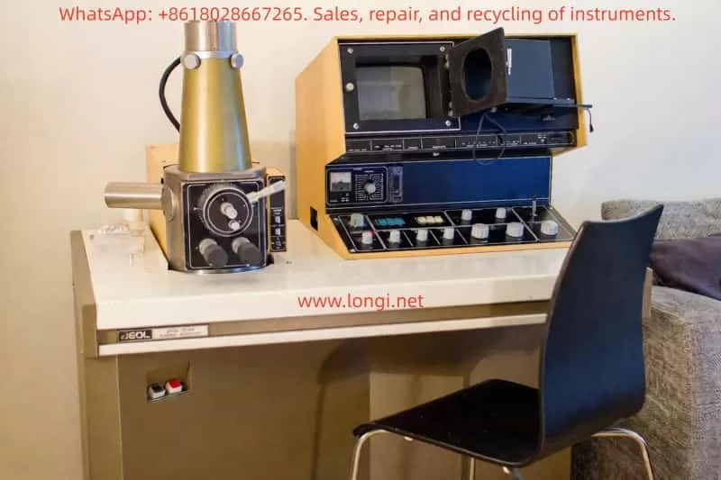
The JEOL JSM-T200 series scanning electron microscope combines simplified operation, easy maintenance, and high performance, enabling even users without professional operational skills to easily obtain high-quality microscopic images. Its advantages, such as a large depth of field, a wide magnification range, and minimized sample preparation requirements, make it an effective instrument in research, quality control, and visual education fields.
1.2 Detailed Explanation of Core Technical Parameters
Electron Optical System Performance Indicators:
- Resolution: Under conditions of 25 kV accelerating voltage and a 20 mm working distance, the resolution can reach 10 nm (100 angstroms).
- Magnification: Continuously adjustable from 15x to 100,000x (15x is only available at a 48 mm working distance).
- Accelerating Voltage: Five options are provided: 2, 5, 10, 15, and 25 kV.
- Electron Gun Filament: Utilizes a pre-aligned box-type tungsten filament.
- Lens System: A three-stage condenser system (two condenser lenses and an objective lens).
- Alignment System: Mechanical alignment.
- Stigmator: Octupole electromagnetic stigmator.
- Image Shift: ±10 μm electromagnetic shift in any direction, controlled by a joystick.
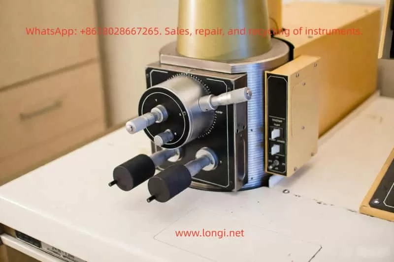
Sample Stage Technical Parameters:
Centered Sample Stage (Type I):
- Sample Size Capacity: Maximum diameter of 10 mm × thickness of 10 mm.
- Movement Range: 10 mm on the X-axis and 20 mm on the Y-axis.
- Tilt Angle: Continuously adjustable from -40° to +90°.
- Rotation Angle: 360° full rotation.
- Working Distance: 20 mm.
- Sample Exchange Method: Achieved by pulling out the sample stage.
1.3 Scanning Detection System Configuration
Secondary and Backscattered Electron Detection: An integrated detector comprising a scintillator, light guide, photomultiplier tube, and collector is used.
Optional Detectors:
- Backscattered Electron Detector: Enables the acquisition of both morphological and compositional images.
- Transmission Electron Detector.
- Cathodoluminescence Detector.
- Sample Current Detector.
- X-ray Detector.
Chapter 2: Equipment Installation and Environmental Requirements
2.1 Power and Water Supply Configuration Requirements
Power Supply:
- Voltage: 100 V, 50/60 Hz, single-phase.
- Power: Basic instrument: 1.2 kVA, accessories: 0.8 kVA, totaling 2 kVA.
- Starting Current: 60 A (0.2 seconds).
- Voltage Fluctuation: No more than ±10%.
- Grounding Requirement: One terminal with a resistance of less than 100 Ω.
Cooling Water System:
- Flow Rate: 2 liters per minute (pressure range: 0.05-0.2 MPa).
- Water Temperature: 20 ± 5°C (outlet water temperature not exceeding 35°C).
2.2 Installation Environment Technical Specifications
Indoor Environmental Requirements:
- Room Temperature: 20 ± 5°C.
- Relative Humidity: Less than 80%.
Ground Vibration: - At 5 Hz: Less than 2 μm peak-to-peak in the X, Y, and Z directions.
- At 10 Hz: Less than 3 μm peak-to-peak in the X, Y, and Z directions.
- At 50 Hz: Less than 8 μm peak-to-peak in the X, Y, and Z directions.
Stray Magnetic Field: Less than 0.3 μT (3 milligauss).
Chapter 3: Comprehensive Analysis of Equipment Operation Procedures
3.1 Standard Startup and Shutdown Procedures
Startup Operation Procedure:
- Turn on the faucet to supply cooling water to the microscope (water flow rate: 1.5-2 liters per minute).
- Turn on the main power switch on the distribution board and press the power switch on the left panel of the control console.
- Wait for 15-30 minutes until the magnification panel displays a reading, indicating that the column vacuum has reached a sufficient level to generate an electron beam and observe samples.
Shutdown Operation Procedure:
- Press the power-off switch.
- Turn off the main power switch.
- Wait for 10-15 minutes to allow the diffusion pump to cool to room temperature.
- Turn off the faucet.
Special Situation Handling:
- Power Failure: The microscope stops automatically. Manual reactivation is required after power restoration.
- Water Supply Failure: The microscope stops automatically. Manual reactivation is required after water supply restoration.
3.2 Technical Specifications for Sample Installation
Centered Sample Stage Installation Steps:
- Press the exhaust switch to allow air into the column.
- Wait approximately 40 seconds for the column to be fully exposed to the atmosphere.
- Insert the sample stub with the sample into the sample holder.
- Adjust the sample height adjustment screw so that the sample surface is flush with the edge of the holder.
- Secure the sample stub using the sample stub fixing screw.
- Return the sample stage to the sample chamber.
- Press the vacuum evacuation switch.
3.3 Detailed Explanation of Image Observation Techniques
Secondary Electron Image (SEI) Observation Setup:
- Set the sample stage control parameters and working distance selector.
- Set the detector panel and control panel control parameters.
- Press the accelerating voltage on button.
- Press the line scan and exposure buttons in sequence.
- Adjust the filament control knob to approximately the 11 o’clock position.
- Gradually rotate the filament control knob to approximately the 2 o’clock position.
- Observe the waveform changes on the CRT screen.
- Press the image mode button to observe the rapid exposure marker and raster.
Backscattered Electron Image (BEI) Observation:
The operation steps are the same as those for SEI observation, but press the BEI button during the initial setup and control the spot size between 12 and 3 o’clock.
3.4 Guide to Using Automatic Functions
Automatic Focusing Mode Operation Procedure:
- Use the coarse focusing control to roughly focus the image.
- Use the fine focusing control to precisely focus the image.
- Press the auto button, and the focus light on the display panel illuminates.
- When the magnification and/or field of view changes, press the auto button on the right side of the focusing panel.
Fully Automatic SEM Image Acquisition:
Images will automatically appear when the power switch is pressed under the following control settings.
Chapter 4: Technical Analysis of Photographic Recording System
4.1 Photographic Recording System Configuration
Comparative Analysis of Four Photographic Recording Systems:
- CSI-1: Standard configuration, Brownie film, 1:0.5 photographic ratio.
- CSI-2: Polaroid film pack, 1:0.75 photographic ratio (optional).
- CSI-3: 35 mm film, 1:0.25 photographic ratio (optional).
- CSI-4: Polaroid loose-leaf film, 1:1 photographic ratio (optional).
4.2 Technical Specifications for Photographic Operation
Scanned Image Photography Procedure:
- Install the recording system on the CRT and secure it with hinge pins.
- Insert the CSI connector into the socket on the display panel.
- Obtain an image on the CRT.
- Swing the CSI onto the CRT and secure it with a latch bar.
4.3 Film Selection and Parameter Settings
Relationship Between Film Sensitivity and f-value:
- 50 ASA → 5.6-8 f.
- 75, 100 ASA → 8-11 f.
- 200 ASA → 11-16 f.
- 400 ASA → 16-22 f.
Notes on the Use of Ultra-High-Speed Film:
Ultra-high-speed film (ASA 3000) is generally not suitable for image recording due to its lower resolution and narrower latitude. The use of such film should be limited to special-purpose photography, such as recording dynamic behavior.
Chapter 5: Equipment Maintenance and Troubleshooting
5.1 Key Points of Daily Maintenance
Oil Rotary Pump Maintenance:
- Regularly check the oil level and replenish as needed.
Diffusion Pump Heater Replacement:
- Turn off the power switch and the main power switch on the distribution board.
- Remove the rear panel.
- Allow the heater assembly to cool.
- Remove the heater assembly.
- Take out the heater from the cover.
- Disconnect the leads connected to the heater and remove the heater.
5.2 Technical Guidance for Component Replacement
Electron Gun Filament Replacement Steps:
- Press the exhaust switch to allow air into the column.
- Loosen the alignment screws and remove the electron gun from the column.
Chapter 6: Advanced Applications and Optimization Techniques
6.1 Advanced Imaging Techniques
Methods for Optimizing Image Contrast:
- High-Contrast Image: Rotate the contrast control knob clockwise until the exposure marker bar exceeds the standard white level bar.
- Low-Contrast Image: Rotate the contrast control knob counterclockwise.
- Automatic Brightness and Contrast Control: First obtain the optimal image brightness and contrast at approximately 1000x magnification, then press the auto control button on the control panel.
6.2 Performance Optimization Strategies
Key Points of Stigmator Correction Techniques:
- Press the image shift button.
- Set the stigmator control knob to the 12 o’clock position.
- Observe the direction of image blur and adjust the stigmator control knob accordingly.
Adjustment of Rapid Exposure Marker:
This marker has been optimized for exposure using ASA 75 film with the lens aperture set to fully open before factory shipment. Therefore, under normal circumstances, as long as the film speed and lens aperture are maintained at ASA 75 and fully open, respectively, no adjustment of the rapid exposure marker is required. However, since the optimal exposure may vary depending on the condition and nature of the sample, occasional adjustments may be necessary. In addition, adjustments will be required when taking high-contrast and low-contrast micrographs.
This user guide covers all operational procedures of the JEOL JSM-T200 series scanning electron microscope, from basic operations to advanced applications, and from routine observations to precision photography. It provides users with a complete and detailed set of operational technical guidance. By following the operational norms outlined in this guide, users can fully leverage the equipment’s performance and obtain high-quality experimental results. At the same time, regular maintenance will ensure the long-term stable operation of the equipment and extend its service life.