
Abstract
This paper provides a comprehensive analysis of the common “Start Interlock 1” fault in ABB ACH580 series variable frequency drives (VFDs), covering fault mechanisms, core causes, diagnostic procedures, and solutions. By integrating official technical manuals, engineering practice cases, and in-depth technical principles, a three-tier diagnostic system—”Signal Chain-Configuration Layer-System Level”—is constructed. This offers engineers in industrial and HVAC fields a full-process guide from basic troubleshooting to complex system debugging, facilitating rapid equipment restoration and preventing fault recurrence.
Introduction
In modern industrial automation and HVAC systems, variable frequency drives serve as the core equipment for motor control, with their stability directly determining production efficiency and energy consumption. The ABB ACH580 series VFDs are widely used in load scenarios such as fans, pumps, and compressors due to their high efficiency, energy savings, and reliability. However, the “Start Interlock 1” fault is one of the high-frequency issues that prevent equipment from starting. This paper provides a systematic fault-solving methodology by dissecting the fault essence through technical analysis and case verification.
1. Fault Essence and Safety Mechanism Analysis
1.1 Definition and Function of “Start Interlock 1”
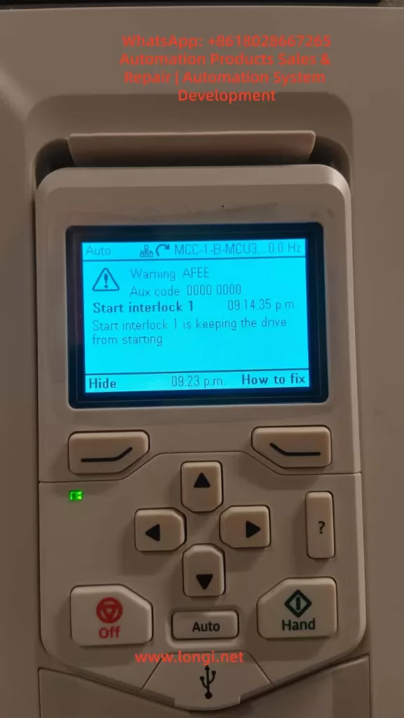
“Start Interlock 1” is an inherent safety protection logic in ABB ACH580 VFDs, designed to ensure that the drive starts the motor only when external conditions are met. Its core function is to monitor preset digital input signals (default DI4 terminal) or communication instruction states to determine whether the device is ready for startup. When the interlock signal is invalid, the VFD immediately blocks the startup process, displays a warning on the panel, and accompanies it with an AFEE code.
1.2 Design Logic of the Safety Mechanism
This protection mechanism adheres to the IEC 61800-5-1 functional safety standard and falls under the category of “Safety-Related Stop Functions” (SRS). Its design logic can be summarized as an “AND gate control”:
- Condition 1: The drive has no hardware faults (e.g., overcurrent, overvoltage, overheating, or other critical errors).
- Condition 2: The external startup instruction is valid (e.g., panel “Hand” mode startup, remote DI signal, or bus control word).
- Condition 3: The “Start Interlock 1” signal is valid (default high level 1 or communication bit enabled).
Only when all three conditions are satisfied can the VFD proceed to the startup sequence; otherwise, interlock protection is triggered.
2. In-Depth Analysis of Core Fault Causes
According to ABB technical manuals and engineering case statistics, “Start Interlock 1” faults can be categorized into four main types:
2.1 External Signal Chain Anomalies (45%)
2.1.1 Digital Input Terminal Faults
- Wiring Issues: Loose, oxidized, or damaged DI4 terminal connections can lead to signal disconnections, common in vibrating environments (e.g., pump rooms) or frequent plugging/unplugging scenarios.
- Power Supply Conflicts: External sensors (e.g., pressure switches, limit switches) may have power supply logic conflicts with the VFD’s DI terminals (e.g., sensor output is PNP, while VFD DI is configured for NPN input).
- Interference Impact: Analog signal cables running parallel to power cables can cause electromagnetic interference (EMI), leading to signal misinterpretation, especially in systems with high-frequency harmonics from VFD speed control.
2.1.2 External Safety Device Activation
In HVAC systems, the interlock signal is often linked to critical safety devices. Typical triggering scenarios include:
- Pressure Protection: Low-pressure switches at pump inlets or high-pressure safety valves at outlets activating.
- Temperature Interlocks: Freeze protection switches in heat exchangers or motor winding over-temperature protections triggering.
- Mechanical Limits: Unreset end-limit switches on damper actuators or belt breakage detection sensors activating.
- Fire Signals: Building fire systems forcing the shutdown of air conditioning units (e.g., FAS system sending a stop command).
2.2 Parameter Configuration Errors (30%)
2.2.1 Incorrect Interlock Source Selection
Parameter 20.41 (Start interlock 1 source) defines the interlock signal source. Common configuration errors include:
- Source Mismatch: Using DI5 terminal while incorrectly setting it to “DI4.”
- Communication Source Conflicts: In Modbus or BACnet control modes, mistakenly setting the interlock source to “digital input” instead of “communication control word bit.”
- Logic Level Errors: Setting parameter 20.42 (Start interlock 1 active level) to “high level active” while the external sensor outputs a low-level signal.
2.2.2 Multi-Pump/PFC System Configuration Anomalies
In constant pressure water supply or multi-fan linkage systems (PFC function), interlock faults are often related to the following parameters:
- Node Configuration Errors: Setting parameter 76.22 (PFC number of nodes) to 3 pumps while only 2 are online, causing master-slave communication timeouts.
- Run Permissive Timeout: Setting parameter 76.64 (Run permissive timeout) too short (e.g., default 5 seconds) while the external PLC startup instruction is delayed, triggering a timeout interlock.
- Synchronization Parameter Inconsistencies: Failure to unify parameters 76.101 (PFC sync word 1) and 76.102 (PFC sync word 2) across multiple pumps, leading to node state misinterpretation.
2.3 Communication and Control Logic Faults (15%)
2.3.1 Fieldbus Communication Anomalies
In industrial Ethernet (e.g., Profinet) or Modbus RTU control scenarios, communication interruptions or data errors can cause interlock signal loss:
- Bus Physical Layer Faults: Damaged network cables, missing terminal resistors (Profinet requires 110Ω terminal resistors), or poor grounding leading to common-mode interference.
- Protocol Data Errors: Incorrect control word bit definitions (e.g., Modbus register address 0x0002 Bit3 for interlock not set to 1).
- Slave Station Timeout: When the VFD acts as a slave, if the master station (e.g., PLC) communication cycle exceeds the parameter 32.05 (Bus timeout) setting (default 2000ms), a “communication interlock failure” is triggered.
2.3.2 Control Mode Switching Conflicts
Frequent switching between “Auto” and “Hand” modes can cause logic conflicts if the external control system does not synchronously update the interlock signal:
- Example: In “Auto” mode, the PLC controls the interlock signal. Switching to “Hand” mode without the PLC sending a release command results in a persistently invalid interlock signal.
2.4 Hardware and Power Supply Faults (10%)
2.4.1 Internal VFD Faults
- DI Terminal Module Damage: Surge voltages (e.g., lightning strikes) or overcurrent can burn out digital input optocouplers, common in outdoor equipment without surge protection devices (SPDs).
- CPU Board Logic Errors: Main control board program crashes or EEPROM parameter corruption can be verified via “factory reset” (parameter 96.06).
- Power Module Anomalies: Excessive ripple (>50mV) in the auxiliary power supply (+24V DC) can cause misinterpretation of DI signal detection circuits.
2.4.2 External Power Supply Fluctuations
- Undervoltage Impact: When the AC 220V control power supply drops below 180V, the internal pull-up resistor voltage division in the DI terminal becomes insufficient, causing the signal to be misinterpreted as “low level.”
- Grounding Faults: System grounding resistance exceeding the standard (>4Ω) can lead to common-mode voltage interference in the DI signal detection circuit.
3. Systematic Diagnostic Process and Tools
3.1 Basic Principles of Fault Diagnosis
Follow a “simple-to-complex, external-to-internal” troubleshooting logic, prioritizing the exclusion of external factors (wiring, power supply, external devices) before checking parameter configurations, and finally considering hardware faults. The “bisection method” is recommended for localization: first determine the interlock source state via panel monitoring parameters, then segmentally test the signal chain.
3.2 Basic Troubleshooting Tools and Steps
3.2.1 Panel Monitoring and Parameter Reading
- Status Parameter Query:
- Enter parameter 10.02 (DI delayed status) to view the interlock-related DI terminal state (e.g., DI4 displaying “0” indicates an invalid signal).
- Check parameter 06.18 (Drive status word 2), where Bit4 (Start interlock 1 active) being “0” indicates an unsatisfied interlock.
- In multi-pump systems, parameter 76.02 (PFC status word) Bit0 (Run permissive active) can determine the system-level interlock state.
- Event Log Analysis:
- Enter parameters 04.40 (Latest fault code) and 04.41 (Fault time) to confirm the fault occurrence time and associated events (e.g., whether accompanied by “Overvoltage” or “Communication loss”).
3.2.2 Electrical Test Tool Applications
- Multimeter: Measure the voltage between the DI terminal and COM (for PNP input, the signal should be +24V when valid and 0V when invalid).
- Oscilloscope: Detect DI signal waveforms to identify glitches or interference (normal signals should have no ripple exceeding 50mV).
- Megohmmeter: Measure DI cable insulation resistance (should be >10MΩ) to exclude grounding faults.
3.3 Advanced Diagnostics: Signal Chain Integrity Testing
Using the default DI4 terminal as an example, construct a “Signal Chain Test Table”:
| Test Node | Test Method | Normal Standard | Abnormal Handling Suggestions |
|---|---|---|---|
| External Sensor Output | Short-circuit sensor contacts and measure output voltage | Consistent with DI terminal power supply logic | Replace sensor or adjust power supply method |
| DI Terminal Wiring | Measure voltage at the terminal block | Consistent with sensor output | Re-crimp terminals, replace shielded cables |
| VFD Internal Circuit | Set parameter 20.41 to “normally closed” | Fault disappears, enabling startup | Check DI module or main control board |
3.4 Multi-System Linkage Diagnostics (HVAC Example)
In building automation systems (BAS), the following steps are recommended for troubleshooting:
- BACnet Communication Test: Monitor the BV20 (Start interlock 1) object status via ABB Drive composer software to confirm whether the BAS system sends “1” (allow startup).
- Linkage Logic Verification: In BAS programming software (e.g., Tridium Niagara), check whether interlock conditions (e.g., “damper fully open” AND “fire signal normal”) are met.
- Timeout Parameter Adjustment: If BAS instruction delays occur, extend parameter 76.64 (Run permissive timeout) to 10 seconds.
4. Full-Scenario Solutions and Cases
4.1 External Signal Chain Repair Solutions
Case 1: Loose DI Terminal in a Pump Room Causing Interlock Failure
- Fault Phenomenon: In a residential secondary water supply system, the ACH580 VFD reports “Start Interlock 1,” with the panel showing DI4 status as 0.
- Troubleshooting Process:
- Measured voltage between DI4 and COM as 0V (normal should be 24V).
- Inspected the terminal block and found a loose DI4 terminal screw with oxidized cables.
- Solution:
- Cleaned terminal oxidation with fine sandpaper, re-crimped cables, and tightened screws.
- Added anti-loosening markers at the terminal block and established a monthly inspection plan.
- Result: Fault disappeared after restart, with stable operation.
Case 2: Electromagnetic Interference Causing Signal Misinterpretation
- Fault Phenomenon: In a shopping mall air conditioning unit, the VFD randomly reports interlock faults with DI signal fluctuations during operation.
- Solution:
- Replaced DI signal lines with twisted-pair shielded cables, grounding the shield at the VFD side.
- Adjusted cable routing to maintain a >30cm distance from power cables.
- Added an RC filter circuit (100Ω resistor + 104 capacitor) before the DI terminal.
- Result: Interference eliminated, with no recurrence of faults.
4.2 Parameter Configuration Optimization Solutions
Case 3: PFC Parameter Configuration Errors in a Multi-Pump System
- Fault Phenomenon: In a factory constant pressure water supply system (3 pumps), pump #2 reports “Start Interlock 1” and cannot participate in rotation.
- Troubleshooting Process:
- Checked parameter 76.22 (PFC number of nodes) set to “3” but parameter 76.25 (Number of motors) set to “2.”
- Found inconsistent parameter 76.101 (Sync word 1) between master and slave stations (master 0x1234, slave 0x1235).
- Solution:
- Unified settings: 76.22=3, 76.25=3.
- Synchronized all pump parameters via Drive composer software (checked “PFC synchronization” option).
- Result: System restarted normally with 3 pumps rotating, and interlock fault resolved.
4.3 Hardware Fault Repair and Prevention
Case 4: DI Module Damage from Surge
- Fault Phenomenon: In an outdoor fan VFD, a “Start Interlock 1” fault occurred after a thunderstorm, with no signal input at DI4 terminal.
- Troubleshooting Process:
- Measured DI4 terminal-to-ground resistance as 0Ω (normal should be infinite), indicating a burned-out optocoupler.
- Solution:
- Replaced the DI input module (model: ACH-0201).
- Installed a surge protection device (Imax≥20kA, Up≤1.5kV) before the DI terminal.
- Result: Module replacement restored signal, with no further damage during subsequent thunderstorms.
4.4 System-Level Interlock Logic Optimization
Case 5: Fire Linkage Interlock Design for a Hospital Cleanroom HVAC System
- Requirement: When a fire signal is triggered, the VFD must immediately stop and prohibit restart (interlock locking).
- Solution:
- Parameter Configuration:
- 20.41=DI6 (fire signal input terminal).
- 20.42=low level active (DI6=0V during fire action).
- 20.45 (Start interlock stop mode)=1 (ramp stop).
- External Circuit: Fire signal relay contacts are串联 (series-connected) to DI6 and COM to ensure reliable disconnection during fire action.
- Parameter Configuration:
- Effect: Upon fire signal trigger, the VFD stops with a 10-second ramp, and the interlock locks, requiring manual reset of the fire signal for restart.
5. Preventive Maintenance and Long-Term Reliability Enhancement
5.1 Regular Maintenance Plan (Recommended Cycles)
- Daily Checks: Panel shows no interlock warnings, and DI signal states are normal (monitored via parameter 10.02).
- Monthly Maintenance: Tighten DI terminal screws, measure insulation resistance, and clean VFD filters.
- Quarterly Calibration: Calibrate DI signal detection thresholds using a signal generator (via Drive composer software).
- Annual Inspection: Test surge protector performance and check grounding resistance (≤4Ω).
5.2 Design-Stage Optimization Recommendations
- Hardware Selection: Prioritize DI terminals with built-in surge protection (e.g., ACH580-01 series).
- Wiring Specifications: Use twisted-pair shielded cables for DI signals, with lengths ≤50 meters, and avoid parallel routing with VFD output cables.
- Redundancy Design: Implement dual-loop inputs for critical interlock signals (e.g., fire, pressure protection) to enhance reliability.
- Parameter Backup: Regularly back up parameters via USB or Drive composer to prevent configuration loss.
5.3 Intelligent Monitoring Solutions
Through the ABB Ability™ cloud platform or local SCADA system, implement a “interlock signal trend analysis” function:
- Real-Time Monitoring: Track DI signal fluctuations and set threshold alarms (e.g., signal jitter >5 times/minute).
- Fault Frequency Logging: Record interlock trigger frequencies and associated events to generate preventive maintenance reports.
- Remote Parameter Adjustment: Enable remote parameter modification and fault reset to reduce on-site intervention time.
Conclusion
The “Start Interlock 1” fault is a direct reflection of the ACH580 VFD’s response to external system states, with its essence being a “mismatch between safety logic and actual operating conditions.” Resolving this fault requires engineers to possess a cross-disciplinary mindset encompassing “electrical + control + system” knowledge. The proposed “three-tier diagnostic system” (signal chain-configuration layer-system level) enables efficient problem localization. In the context of Industry 4.0, combining preventive maintenance with intelligent monitoring not only resolves existing faults quickly but also facilitates a transition from “reactive maintenance” to “proactive prevention,” ensuring long-term equipment reliability throughout its lifecycle.