
I. FC-111 Inverter Local Control Panel (LCP) Functions and Basic Settings
1. Local Control Panel (LCP) Function Introduction
The Local Control Panel (LCP) of the Danfoss FC-111 inverter is divided into four functional areas, providing users with an intuitive operating interface:
A. Display Area:
- LCP 32 Model: Displays 3 lines of alphanumeric information
- LCP 31 Model: Displays 2 lines
- Displayed Content: Parameter number/name (1), parameter value (2), menu number (3), motor direction indicator (4), and current menu status (5)
B. Menu Keys:
- [Menu] Key: Switches between the Status Menu, Quick Menu, and Main Menu
- Status Menu: Displays real-time operating data such as motor frequency (Hz), current (A), power (kW/hp), etc.
- Quick Menu: Provides quick access to commonly used functions such as open-loop/closed-loop application guides and motor settings
- Main Menu: Allows access to all parameter settings
C. Navigation Keys and Indicators:
- Yellow Com. (Communication) Indicator: Flashes during bus communication
- Green On (Power) Indicator: Shows power supply status
- Yellow Warn. (Warning) Indicator: Lights up when a warning occurs
- Red Alarm Indicator: Lights up when a fault occurs
- [Back] Key: Returns to the previous menu level
- Directional Keys: Navigate through parameter groups/parameters/parameter values
- [OK] Key: Selects parameters/confirms modifications
D. Operation Keys and Indicators:
- [Hand On] Manual Start Key: Starts the inverter locally
- [Off/Reset] Stop/Reset Key: Stops operation or resets alarms
- [Auto On] Automatic Start Key: Allows control via control terminals or communication
2. Password Setting and Parameter Access Restrictions
Setting the Main Menu Password:
- Access parameter 0-60 Main Menu Password
- Enter a 3-digit numeric password (1-999). Setting it to 0 disables the password function.
- The password will be hidden from display after being set.
Parameter Access Restriction Settings:
- Through parameter 0-61 Access to Main Menu w/o Password, different levels of access control can be implemented:
- [0] Full access: Full access (default)
- [1] LCP read-only: Prevents unauthorized editing
- [2] LCP no access: Prohibits viewing and editing
- [3] Bus read-only: Read-only access via the fieldbus
- [5] All read-only: Comprehensive read-only protection
Password Protection Mechanism Features:
- After the password takes effect, accessing via the [Main Menu] key requires entering the password.
- Different permission levels can be set to meet maintenance and operational needs.
- Bus communication access permissions can be set independently.
- Forgotten passwords can be reset by initializing the inverter to restore factory settings.
3. Parameter Restoration to Factory Settings
The FC-111 provides two initialization methods to restore parameters to factory defaults:
Method 1: Recommended Initialization (Recommended):
- Access parameter 14-22 Operation Mode
- Select [2] Initialization and press [OK] to confirm
- Disconnect the inverter from the power supply and wait for the LCP to fully power down
- Reconnect the power supply to complete the initialization
- Parameters Retained: Motor direction, communication parameters, operating time records, alarm logs, etc., will not be reset.
Method 2: Two-Key Initialization:
- Disconnect the inverter from the power supply
- Simultaneously press and hold the [OK] and [Menu] keys without releasing them
- Keep the keys pressed for 10 seconds while reconnecting the power supply
- Release the keys to complete the initialization
Notes:
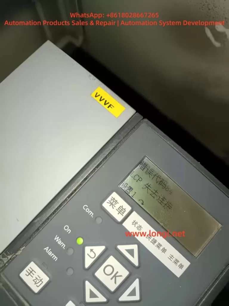
- The initialization process takes approximately 1 minute. Alarm 80 indicates success.
- Initialization clears all user parameter settings.
- It is recommended to back up parameters to the LCP (using 0-50 LCP Copy) before initialization.
II. External Terminal Control and Speed Adjustment Settings
1. External Terminal Forward/Reverse Control
Wiring Scheme:
| Function | Terminal | Voltage Type |
|---|---|---|
| +24V Output | Terminal 12 | PNP Signal |
| Forward Start | Terminal 18 | Digital Input |
| Reverse Control | Terminal 19 | Digital Input |
| Common/Stop | Terminal 27 | Digital Input |
Parameter Setting Steps:
Configuring Digital Input Mode:
- Parameter 5-00 Digital Input Mode: [0] PNP (default)
Setting Terminal Functions:
- Parameter 5-10 Terminal 18 Digital Input: [8] Start
- Parameter 5-11 Terminal 19 Digital Input: [10] Reversing
- Parameter 5-12 Terminal 27 Digital Input: [6] Stop inverse
Enabling Bidirectional Operation:
- Parameter 4-10 Motor Speed Direction: [2] Both directions
Setting Rotation Direction Reference:
- Parameter 1-06 Clockwise Direction: [0] Normal (defines what constitutes clockwise rotation)
Operation Logic:
- Terminal 18 = 1: Forward start
- Terminal 18 = 1 and Terminal 19 = 1: Reverse operation
- Terminal 27 = 0: Stop (normally closed wiring)
2. External Potentiometer Speed Adjustment
Recommended Wiring Scheme:
| Function | Terminal | Technical Requirements |
|---|---|---|
| +10V Power Supply | Terminal 50 | Supplies power to the potentiometer |
| Analog Input | Terminal 53 | Connects to the middle tap of the potentiometer |
| Signal Ground | Terminal 54 | Connects to the other end of the potentiometer |
Parameter Configuration Process:
Basic Settings:
- Parameter 3-15 Reference 1 Source: [1] Analog Input 53
- Parameter 6-19 Terminal 53 Mode: [1] Voltage
Calibrating Input Range:
- Parameter 6-10 Terminal 53 Low Voltage: 0.07V (corresponds to 0% speed)
- Parameter 6-11 Terminal 53 High Voltage: 10V (corresponds to 100% speed)
Setting Frequency Range:
- Parameter 3-02 Minimum Reference: 0Hz (lower limit)
- Parameter 3-03 Maximum Reference: 50Hz (upper limit, adjustable)
Filter Settings (Optional):
- Parameter 6-16 Terminal 53 Filter Time Constant: 0.01s (default)
Advanced Configuration Options:
- A second reference source can be set to achieve speed superposition.
- Disconnection detection can be implemented using parameter 6-01 Live Zero Timeout Function.
- Acceleration/deceleration ramp times can be set using parameters 3-41/3-42.
III. Fault Diagnosis and Handling
1. Common Fault Codes and Handling Methods
The FC-111 inverter provides comprehensive fault protection functions. Main faults can be classified into the following categories:
Motor-Related Faults:
- Alarm 14: Motor overheating
- Cause: ETR calculated temperature exceeds the limit or the thermistor is triggered.
- Handling: Check motor load/cooling; verify parameter settings 1-90/1-93.
- Alarm 16: Motor phase loss
- Cause: Motor cable or connection fault.
- Handling: Check three-phase cables; confirm parameter 4-58 is set to [1] Trip 10s.
Power-Related Faults:
- Alarm 4: DC bus overvoltage
- Cause: Deceleration time is too short or grid voltage is too high.
- Handling: Adjust parameter 3-42 deceleration time; enable parameter 2-17 overvoltage control.
- Alarm 8: DC bus undervoltage
- Cause: Main power supply interruption or rectifier bridge fault.
- Handling: Check input power supply; verify parameter 14-10 settings.
Inverter Faults:
- Alarm 5: Inverter overload
- Cause: Output current exceeds hardware limits.
- Handling: Check motor load; adjust parameter 4-18 current limit.
- Alarm 12: Inverter overheating
- Cause: Heat sink temperature is too high.
- Handling: Clean air ducts; check ambient temperature; verify parameter 14-52 fan control.
2. Fault Troubleshooting Steps
Viewing Alarm Information:
- Check historical alarm records via parameter 15-30 Alarm Log.
- Parameter 15-31 InternalFaultReason provides detailed fault causes.
Resetting Operations:
- Lightly press the [Off/Reset] key to reset non-locking alarms.
- Locking alarms must be reset after the fault cause has been eliminated.
Advanced Diagnostics:
- Parameter group 16-9 Diagnosis Readouts* provides detailed diagnostic data.
- The extended status word (parameter 16-94) displays specific protection trigger conditions.
Preventive Measures:
- Regularly check parameter 16-35 Inverter Thermal value.
- Monitor parameter 16-30 DC Link Voltage fluctuation range.
- Record parameter 15-00 Operating hours runtime.
IV. Advanced Function Applications
1. Multi-Speed and PID Control
Multi-Speed Settings:
- Preset 8 speed values in parameter 3-10 Preset Reference.
- Use terminals 18/19/29 with functions [16][17][18] to select speed segments.
- Set switching delays using parameters 5-34/5-35.
PID Control Configuration:
- Set parameter 1-00 Configuration Mode to [3] Process Closed Loop.
- Select feedback signal source using parameter 20-00 Feedback 1 Source.
- Set PID parameters:
- Proportional gain (20-93)
- Integral time (20-94)
- Differential time (20-95, optional)
2. Energy-Saving and Protection Functions
Automatic Energy Optimization (AEO):
- Set parameter 1-03 Torque Characteristics to [3] Auto Energy Optim.
- Adjust parameter 14-41 to set the minimum magnetization current.
Motor Protection Settings:
- Select protection mode using parameter 1-90 Motor Thermal Protection.
- Set preheat current using parameter 2-00 DC Hold Current.
- Enable phase loss protection using parameter 4-58 Missing Motor Phase.
Maintenance Reminder Functions:
- Monitor parameter 15-04 Over Temp’s over-temperature count.
- View parameter 15-05 Over Volt’s overvoltage event records.
- Use parameter 18-10 FireMode Log to check fire mode records.
V. Usage Recommendations and Precautions
Installation Precautions:
- Ensure grounding conductors comply with safety regulations (leakage current > 3.5mA).
- Motor cable length settings (parameter 1-42) affect control performance.
- Separate strong and weak current cables during wiring.
Parameter Setting Tips:
- Use the “Quick Menu” for rapid debugging.
- Back up parameters using the 0-50 LCP Copy function.
- Record original values before modifying important parameters.
Maintenance Recommendations:
- Regularly check parameter 15-37 inverter rated current.
- Check parameter 1-29 AMA (Automatic Motor Adaptation) every six months.
- Clean the heat sink and check fan operation (parameter 14-53) annually.
Safety Warnings:
- Wait for the capacitors to discharge after powering off (refer to the discharge time table).
- Only qualified personnel are allowed to operate (refer to IEC 60364 standard).
- Pay special attention to parameter 1-70 start mode settings for permanent magnet motors.
This guide is based on the latest FC111 programming manual (V1.01). Please refer to the actual device version for practical applications. For complex application scenarios, it is recommended to use the MCT 10 setup software for parameter optimization and monitoring. Through reasonable settings and regular maintenance, the FC-111 inverter can provide reliable and stable motor control solutions.