
1. Introduction
The Mastersizer 3000 is a widely used laser diffraction particle size analyzer manufactured by Malvern Panalytical. It has become a key analytical tool in industries such as pharmaceuticals, chemicals, cement, food, coatings, and materials research. By applying laser diffraction principles, the instrument provides rapid, repeatable, and accurate measurements of particle size distributions.
Among its various configurations, the Aero S dry powder dispersion unit is essential for analyzing dry powders. This module relies on compressed air and vacuum control to disperse particles and to ensure that samples are introduced without agglomeration. Therefore, the stability of the pneumatic and vacuum subsystems directly affects data quality.
In practice, faults sometimes occur during startup or system cleaning. One such case involved a user who reported repeated errors during initialization and cleaning. The system displayed the following messages:
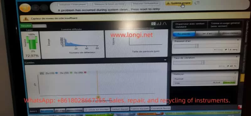
- “Pression d’air = 0 bar” (Air pressure = 0 bar)
- “Capteur de niveau de vide insuffisant” (Vacuum level insufficient)
- “A problem has occurred during system clean. Press reset to retry”
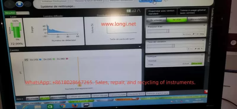
While the optical laser subsystem appeared normal (laser intensity ~72.97%), the pneumatic and vacuum functions failed, preventing measurements.
This article will analyze the fault systematically, covering:
- The operating principles of the Mastersizer 3000 pneumatic and vacuum systems
- Fault symptoms and possible causes
- A detailed troubleshooting and repair workflow
- Case study insights
- Preventive maintenance measures
The goal is to form a comprehensive technical study that can be used as a reference for engineers and laboratory technicians.
2. Working Principle of the Mastersizer 3000 and Pneumatic System
2.1 Overall Instrument Architecture
The Mastersizer 3000 consists of the following core modules:
- Optical system – Laser light source, lenses, and detectors that measure particle scattering signals.
- Dispersion unit – Either a wet dispersion unit (for suspensions) or the Aero S dry powder dispersion system (for powders).
- Pneumatic subsystem – Supplies compressed air to the Venturi nozzle to disperse particles.
- Vacuum and cleaning system – Provides suction during cleaning cycles to remove residual particles.
- Software and sensor monitoring – Continuously monitors laser intensity, detector signals, air pressure, vibration rate, and vacuum level.
2.2 The Aero S Dry Dispersion Unit
The Aero S operates based on Venturi dispersion:
- Compressed air (typically 4–6 bar, oil-free and dry) passes through a narrow nozzle, creating high-velocity airflow.
- Powder samples introduced into the airflow are broken apart into individual particles, which are carried into the laser measurement zone.
- A vibrator ensures continuous and controlled feeding of powder.
To monitor performance, the unit uses:
- Air pressure sensor – Ensures that the compressed air pressure is within the required range.
- Vacuum pump and vacuum sensor – Used during System Clean cycles to generate negative pressure and remove any residual powder.
- Electro-pneumatic valves – Control the switching between measurement, cleaning, and standby states.
2.3 Alarm Mechanisms
The software is designed to protect the system:
- If the air pressure < 0.5 bar or the pressure sensor detects zero, it triggers “Pression d’air = 0 bar”.
- If the vacuum pump fails or the vacuum sensor detects insufficient negative pressure, it triggers “Capteur de niveau de vide insuffisant”.
- During cleaning cycles, if either air or vacuum fails, the software displays “A problem has occurred during system clean”, halting the process.
3. Fault Symptoms
3.1 Observed Behavior
The reported system displayed the following symptoms:
- Air pressure reading = 0 bar (even though external compressed air was connected).
- Vacuum insufficient – Cleaning could not be completed.
- Each attempt at System Clean resulted in the same error.
- Laser subsystem operated normally (~72.97% signal), confirming that the fault was confined to pneumatic/vacuum components.
3.2 Screen Snapshots
- Laser: ~72.97% – Normal.
- Air pressure: 0 bar – Abnormal.
- Vacuum insufficient – Abnormal.
- System Clean failed – Symptom repeated after each attempt.
4. Possible Causes
Based on the working principle, the issue can be classified into four categories:
4.1 External Compressed Air Problems
- Insufficient pressure supplied (below 3 bar).
- Moisture or oil contamination in the air supply leading to blockage.
- Loose or disconnected inlet tubing.
4.2 Internal Pneumatic Issues
- Venturi nozzle blockage – Powder residue, dust, or oil accumulation.
- Tubing leak – Cracked or detached pneumatic hoses.
- Faulty solenoid valve – Valve stuck closed, preventing airflow.
4.3 Vacuum System Issues
- Vacuum pump not starting (electrical failure).
- Vacuum pump clogged filter, reducing suction.
- Vacuum hose leakage.
- Defective vacuum sensor giving false signals.
4.4 Sensor or Control Electronics
- Air pressure sensor drift or failure.
- Vacuum sensor malfunction.
- Control board failure in reading sensor values.
- Loose electrical connections.
5. Troubleshooting Workflow
A structured troubleshooting approach helps isolate the problem quickly.
5.1 External Checks
- Verify that compressed air supply ≥ 4 bar.
- Inspect inlet tubing and fittings for leaks or loose connections.
- Confirm that a dryer/filter is installed to ensure oil-free and moisture-free air.
5.2 Pneumatic Circuit Tests
- Run manual Jet d’air in software. Observe if air flow is audible.
- If no airflow, dismantle and inspect the Venturi nozzle for blockage.
- Check solenoid valve operation: listen for clicking sound when activated.
5.3 Vacuum System Tests
- Run manual Clean cycle. Listen for the vacuum pump running.
- Disconnect vacuum tubing and feel for suction.
- Inspect vacuum filter; clean or replace if clogged.
- Measure vacuum with an external gauge.
5.4 Sensor Diagnostics
- Open Diagnostics menu in the software.
- Compare displayed sensor readings with actual measured pressure/vacuum.
- If real pressure exists but software shows zero → sensor fault.
- If vacuum pump works but error persists → vacuum sensor fault.
5.5 Control Electronics
- Verify power supply to pneumatic control board.
- Check connectors between sensors and board.
- If replacing sensors does not fix the issue, the control board may require replacement.
6. Repair Methods and Case Analysis
6.1 Air Supply Repairs
- Adjust and stabilize supply at 5 bar.
- Install or replace dryer filters to prevent moisture/oil contamination.
- Replace damaged air tubing.
6.2 Internal Pneumatic Repairs
- Clean Venturi nozzle with alcohol or compressed air.
- Replace faulty solenoid valves.
- Renew old or cracked pneumatic tubing.
6.3 Vacuum System Repairs
- Disassemble vacuum pump and clean filter.
- Replace vacuum pump if motor does not run.
- Replace worn sealing gaskets.
6.4 Sensor Replacement
- Replace faulty pressure sensor or vacuum sensor.
- Recalibrate sensors after installation.
6.5 Case Study Result
In the real case:
- External compressed air supply was only 1.4 bar, below specifications.
- The vacuum pump failed to start (no noise, no suction).
- After increasing compressed air supply to 5 bar and replacing the vacuum pump, the system returned to normal operation.
7. Preventive Maintenance Recommendations
7.1 Air Supply Management
- Maintain external compressed air ≥ 4 bar.
- Always use an oil-free compressor.
- Install a dryer and oil separator filter, replacing filter elements regularly.
7.2 Routine Cleaning
- Run System Clean after each measurement to avoid powder buildup.
- Periodically dismantle and clean the Venturi nozzle.
7.3 Vacuum Pump Maintenance
- Inspect and replace filters every 6–12 months.
- Monitor pump noise and vibration; service if abnormal.
- Replace worn gaskets and seals promptly.
7.4 Sensor Calibration
- Perform annual calibration of air pressure and vacuum sensors by the manufacturer or accredited service center.
7.5 Software Monitoring
- Regularly check the Diagnostics panel to detect early drift in sensor readings.
- Record data logs to compare performance over time.
8. Conclusion
The Mastersizer 3000, when combined with the Aero S dry dispersion unit, relies heavily on stable air pressure and vacuum control. Failures such as “Air pressure = 0 bar” and “Vacuum level insufficient” disrupt operation, especially during System Clean cycles.
Through systematic analysis, the faults can be traced to:
- External compressed air issues (low pressure, leaks, contamination)
- Internal pneumatic blockages or valve faults
- Vacuum pump failures or leaks
- Sensor malfunctions or control board errors
A structured troubleshooting process — starting from external supply → pneumatic circuit → vacuum pump → sensors → electronics — ensures efficient fault localization.
In the reported case, increasing the compressed air pressure and replacing the defective vacuum pump successfully restored the instrument.
For laboratories and production environments, preventive maintenance is crucial:
- Ensure stable, clean compressed air supply.
- Clean and service nozzles, filters, and pumps regularly.
- Calibrate sensors annually.
- Monitor diagnostics to detect anomalies early.
By applying these strategies, downtime can be minimized, measurement accuracy preserved, and instrument lifespan extended.