
Introduction
The JLS Inverter E Series is a high-performance motor control device widely used in industrial automation. Its user manual provides comprehensive guidance on installation, configuration, and maintenance, enabling users to operate the inverter efficiently. This article, based on the manual, offers a detailed guide on the operation panel functions, terminal-based forward/reverse control, external potentiometer frequency adjustment, and common fault codes with their solutions. The goal is to provide users with a practical and thorough reference for utilizing the JLS Inverter E Series effectively.
1. Operation Panel Functions
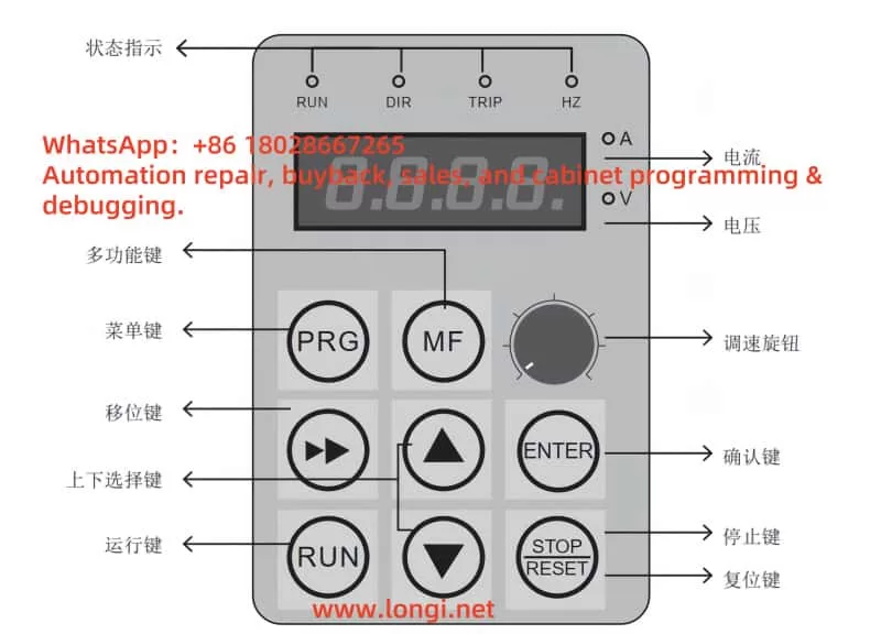
The operation panel is the primary interface for interacting with the JLS Inverter E Series, allowing users to configure parameters, monitor operations, and diagnose faults. Below is an overview of its key functions and usage instructions.
1.1 Display and Function Buttons
- Display Screen: The LCD screen displays real-time information such as parameter values, operating frequency, output current, and fault codes. It supports multiple language options for user convenience.
- Function Buttons:
- PRG/ENTER Key: Enters parameter programming mode or confirms parameter changes.
- Up/Down Keys (▲/▼): Navigate through parameter lists or adjust parameter values.
- Left/Right Keys (◄/►): Switch between parameter groups or move the cursor during parameter editing.
- RUN Key: Starts the inverter, initiating motor operation.
- STOP/RESET Key: Stops the inverter or resets it during a fault condition.
- DIP Switch: Located inside the operation panel, used to set parameter access restrictions.
1.2 Restoring Factory Settings
To reset the inverter to its default configuration, follow these steps to restore factory settings:
- Press the PRG/ENTER Key to enter programming mode.
- Use the ▲/▼ Keys to select the parameter group “F0” (Basic Function Group).
- Use the ◄/► Keys to locate parameter “F0.00” (Restore Factory Settings).
- Set “F0.00” to “1” (indicating a factory reset).
- Press the PRG/ENTER Key to confirm.
- The inverter will restart automatically, restoring all parameters to their factory defaults.
1.3 Setting and Clearing Passwords
To prevent unauthorized parameter modifications, the inverter supports password protection. Below are the steps to set and clear a password:
- Setting a Password:
- Enter programming mode by pressing the PRG/ENTER Key.
- Select the “F0” parameter group.
- Navigate to parameter “F0.01” (Password Setting).
- Enter a 4-digit password (e.g., “1234”).
- Press the PRG/ENTER Key to save the password.
- Clearing a Password:
- Enter programming mode.
- Input the current password to unlock parameter access.
- Navigate to parameter “F0.01”.
- Set “F0.01” to “0” (to disable the password).
- Press the PRG/ENTER Key to confirm.
1.4 Parameter Access Restrictions
Parameter access can be restricted using the DIP switch inside the operation panel. Follow these steps:
- Open the operation panel to access the internal DIP switch.
- Set the switch position based on the desired access level:
- Position 1 (ON): Allows access to all parameters.
- Position 2 (OFF): Restricts access to advanced parameters, allowing only basic parameters to be modified.
- Close the panel and restart the inverter to apply the settings.
2. Terminal-Based Forward/Reverse Control and External Potentiometer Frequency Adjustment
The JLS Inverter E Series supports motor forward/reverse control via terminals and frequency adjustment using an external potentiometer. Below are the detailed steps for implementation.
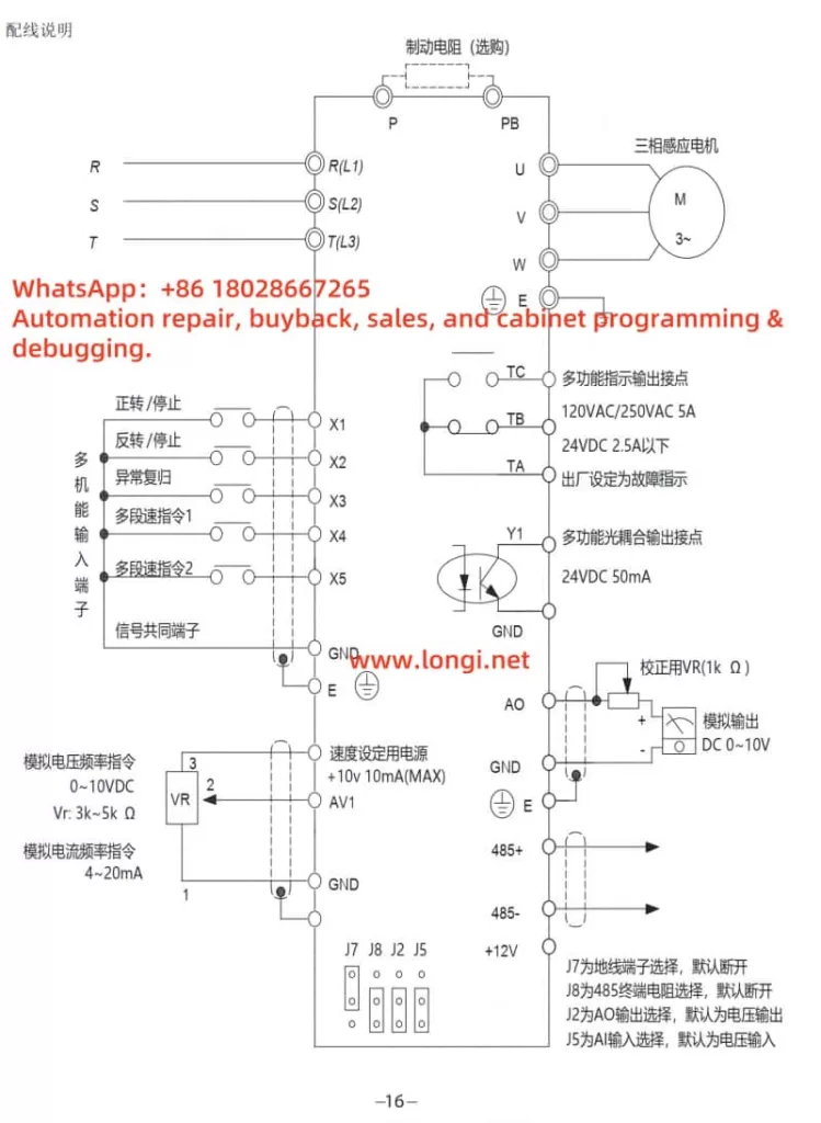
2.1 Wiring Configuration
- Forward/Reverse Control:
- Connect an external switch or PLC output to the inverter’s “FWD” (forward) and “REV” (reverse) terminals.
- Connect the control signal’s common terminal to the “COM” terminal.
- External Potentiometer Frequency Adjustment:
- Connect the potentiometer’s middle tap to the “AI1” terminal (Analog Input 1).
- Connect the potentiometer’s two ends to the “+10V” (power supply) and “GND” (ground) terminals.
2.2 Parameter Settings
- Forward/Reverse Control:
- Enter programming mode.
- Select parameter group “F1” (Operation Control Group).
- Set “F1.00” (Operation Command Source) to “1” (Terminal Control).
- Set “F1.01” (Forward Control) to “0” (FWD terminal controls forward rotation).
- Set “F1.02” (Reverse Control) to “1” (REV terminal controls reverse rotation).
- External Potentiometer Frequency Adjustment:
- Enter programming mode.
- Select parameter group “F2” (Frequency Setting Group).
- Set “F2.00” (Frequency Reference Source) to “2” (AI1 Analog Input).
- Based on the potentiometer’s characteristics, configure parameters “F2.01” (AI1 Minimum Input) to “F2.04” (AI1 Maximum Input) to calibrate the frequency range.
- Example: Set “F2.01” to 0V corresponding to 0Hz and “F2.04” to 10V corresponding to 50Hz.
3. Fault Codes and Troubleshooting
The JLS Inverter E Series manual lists common fault codes and their troubleshooting methods. Below are typical faults and their solutions:
- E001: Overcurrent Fault
- Cause: Excessive motor load, overly short acceleration time, or output short circuit.
- Solution:
- Check and reduce motor load.
- Extend acceleration time (adjust parameter “F3.01”).
- Inspect output wiring to ensure no short circuits.
- E002: Overvoltage Fault
- Cause: High supply voltage, overly short deceleration time, or faulty braking resistor.
- Solution:
- Verify power supply voltage stability.
- Extend deceleration time (adjust parameter “F3.02”).
- Check the braking resistor for damage or poor connection.
- E003: Undervoltage Fault
- Cause: Low supply voltage or poor wiring connections.
- Solution:
- Ensure the power supply voltage is within the specified range.
- Check wiring connections for secure contacts.
- E004: Overheat Fault
- Cause: Poor heat dissipation, high ambient temperature, or faulty fan.
- Solution:
- Improve ventilation to enhance heat dissipation.
- Reduce ambient temperature.
- Inspect fan operation and replace if necessary.
- E005: Motor Overload
- Cause: Excessive load or incorrect motor parameter settings.
- Solution:
- Reduce motor load.
- Verify that motor parameters match the actual motor specifications.
Conclusion
The JLS Inverter E Series is a versatile and robust solution for industrial motor control, offering flexible configuration options and reliable performance. Mastering the user manual’s instructions is critical for ensuring stable operation and extending the equipment’s lifespan. This article has provided a comprehensive guide to the operation panel functions, terminal control setup, and fault troubleshooting, serving as a practical reference for users. In practice, adhere strictly to the manual’s guidelines and perform regular maintenance to ensure the inverter’s safety and reliability.