Posted on

Systematic Analysis and Engineering-Level Diagnosis of Communication Failure in Malvern Mastersizer 2000

1. Introduction: Background of the Communication Error

The Malvern Mastersizer 2000 is one of the most widely deployed laser diffraction particle size analyzers worldwide. Its reputation is built on a stable optical system, mature algorithms, and long-term repeatability. However, as the instrument ages, a specific class of failures becomes increasingly common in field applications: loss of communication between the instrument and the host computer.

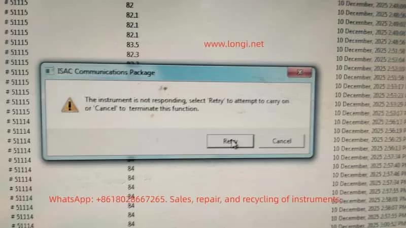
A typical software warning appears as:

ISAC Communications Package
The instrument is not responding

From the user’s perspective, this message is often interpreted as a software crash or a temporary computer issue. From an engineering and maintenance standpoint, however, this error is a clear indicator of a system-level communication failure, involving hardware, power stability, and embedded control reliability rather than measurement parameters or optics.

This article provides a structured, engineering-level analysis of this failure mode in the Mastersizer 2000, focusing on root causes, diagnostic logic, and realistic repair considerations.


Mastersizer 2000,

2. System Architecture Overview of Mastersizer 2000

Understanding this error requires a clear understanding of how the Mastersizer 2000 is architected at a system level.

The instrument can be divided into four major functional subsystems:

  1. Host PC and Malvern control software
  2. Communication layer (ISAC Communications Package)
  3. Internal controller system (embedded control board)
  4. Optical and fluid handling subsystems

The ISAC Communications Package is not merely an application layer component. It is responsible for:

  • Establishing and maintaining the communication session between PC and instrument
  • Periodic polling of instrument status (heartbeat mechanism)
  • Transmission of operational commands (start, stop, align, clean, measure)
  • Receiving and decoding status responses and operational data

When the software reports “Instrument is not responding”, the real meaning is:

The instrument failed to return a valid response within the defined communication timeout window

This indicates a failure somewhere along the communication and control chain, not a measurement error.


3. What This Error Is NOT

Before diagnosing the real cause, it is critical to eliminate several common misconceptions.

3.1 Not a Simple Software Crash

In many cases, background data logging continues even after the warning appears. This confirms that:

  • The Windows operating system is still running
  • The Malvern application itself has not crashed
  • The failure occurs at the communication interface or embedded control level

3.2 Not an Optical or Laser Failure

Failures related to lasers, detectors, or alignment typically result in:

  • Light intensity errors
  • Background measurement failures
  • Optical calibration errors

They do not directly cause a total communication timeout.

3.3 Not a Sample or Method Issue

Sample concentration, dispersion settings, pump speed, or measurement SOPs may affect results, but they do not cause the instrument controller to stop responding at the protocol level.


4. Engineering Interpretation of the Communication Failure

From a system engineering perspective, the error can be summarized as follows:

The host PC cannot complete a communication transaction with the instrument controller within the allowed time

The communication path is a serial chain:

PC software → OS USB stack → PC USB controller → USB cable → instrument USB interface → internal communication module → controller board MCU → response returned

Any instability along this chain will result in the same final symptom: Instrument not responding.


ISAC Communications Package
The instrument is not responding

5. Root Causes in Mastersizer 2000 (Ranked by Probability)

5.1 Unstable USB Communication Path (Highest Probability)

This is the most common cause in aging Mastersizer 2000 units.

Typical symptoms:

  • Instrument is detected, but disconnects during operation
  • Retry sometimes works, sometimes fails
  • Behavior differs between computers
  • Connection drops after several minutes of runtime

Engineering causes:

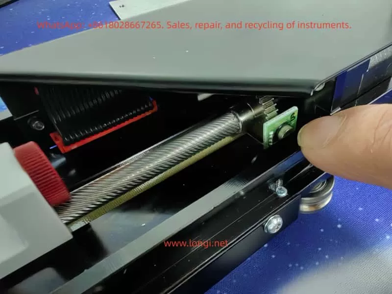
  • Aging or poorly shielded USB cables
  • Use of USB extension cables or hubs
  • Fatigue or micro-cracks in the instrument USB connector solder joints
  • Degraded internal USB-to-serial communication module

If replacing the USB cable and connecting directly to a motherboard USB port improves stability, the issue is hardware-level communication reliability, not software.


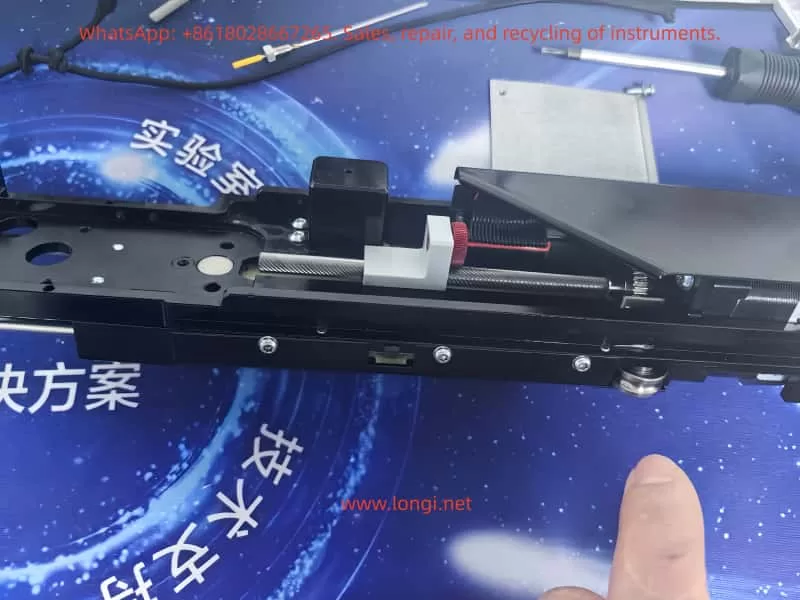
5.2 Controller Board Marginal Operation

After long service life (typically >8–10 years), the controller board often enters a marginal operating state.

Typical symptoms:

  • Cold start works normally
  • Communication fails after warm-up
  • Power cycling temporarily restores operation

Underlying causes:

  • MCU operating near voltage tolerance limits
  • Increased ESR in electrolytic capacitors
  • Power rail ripple exceeding acceptable margins
  • Temperature-related timing instability

This class of failure is often misdiagnosed as intermittent software behavior but is fundamentally a hardware aging issue.


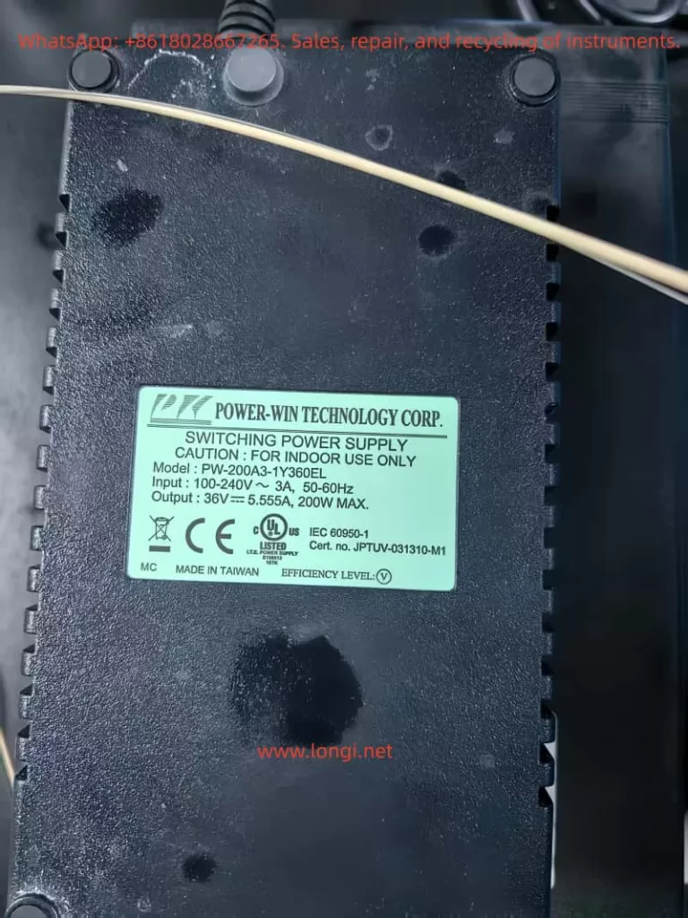
5.3 Internal Power Supply Degradation or Poor Mains Quality

This factor is especially common in regions with unstable mains power.

Contributing conditions:

  • Line voltage fluctuations
  • Lack of voltage regulation
  • Aging internal switching power supplies

Resulting behavior:

  • Momentary drops in 5 V or 3.3 V rails
  • Internal controller or communication module resets
  • PC reports communication timeout

The instrument may appear powered and operational while internally experiencing repeated micro-resets.


5.4 Operating System or Driver Environment (Low Probability)

This factor should only be prioritized when:

  • A new PC has been introduced
  • The operating system was recently reinstalled
  • Non-standard or unofficial software versions are used

In stable legacy systems, OS-level causes are relatively rare.


6. Structured Diagnostic Procedure (Field-Applicable)

A professional diagnostic approach must be systematic and repeatable.

Step 1: Full Cold Reset

  • Shut down software
  • Power off instrument
  • Disconnect power for at least 5 minutes

Step 2: Minimize Communication Path

  • Replace USB cable
  • Eliminate USB hubs or extensions
  • Use rear motherboard USB ports

Step 3: Test with an Alternate Computer

  • Clean OS environment
  • No additional instrument drivers

Step 4: Idle Stability Test

  • Do not perform measurements
  • Maintain connection for at least 10 minutes

If communication still fails under these conditions, the fault can be confidently attributed to instrument-side hardware.


7. Repair and Commercial Considerations

From a third-party service and repair perspective, this fault class has clear implications:

  • It is not a user operation issue
  • Reinstalling software is rarely a true solution
  • In many cases, the instrument is repairable
  • Risk and cost must be evaluated at board level

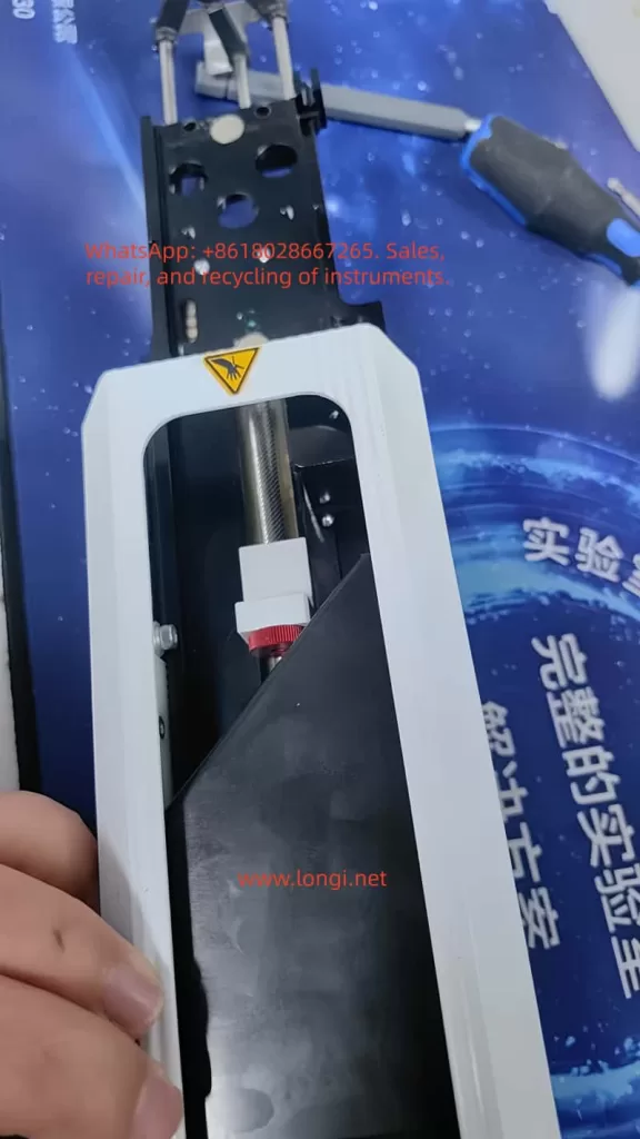
Viable repair directions:

  • USB connector and communication module repair
  • Controller board power conditioning (capacitors, regulators)
  • Internal power supply refurbishment

Cases where repair is not recommended:

  • Severe multi-board corrosion
  • Controller MCU failure without replacement options

8. Conclusion

The error message “ISAC Communications Package – Instrument not responding” is not vague or generic. In the Mastersizer 2000, it represents a classic aging-related system-level failure involving communication stability and embedded control reliability.

The correct solution is not repeated retries or blind software reinstallation, but:

  • Understanding the communication architecture
  • Differentiating software symptoms from hardware causes
  • Making informed engineering and commercial repair decisions
Posted on

Analysis and Systematic Solutions for ER.022 Fault in Weichuang Servo SD700 Series

Introduction

In the field of modern industrial automation, servo systems are the core components for high-precision motion control, and their stability and reliability directly impact the efficiency and product quality of production lines. The SD700 series servo drives launched by Weichuang Electric have gained market recognition due to their excellent performance and wide applications. However, in actual operation, the ER.022 fault code, as a common system abnormality alert, poses a challenge to technicians. This article will provide a systematic technical guide for technicians from the aspects of definition, causes, diagnosis, solutions, and prevention.

ER.022 fualt

I. Overview of the ER.022 Fault Code

1.1 Definition of the Fault Code

The ER.022 fault code in the Weichuang Servo SD700 series represents a “system and checksum anomaly,” indicating that the servo drive has detected inconsistencies in system parameters, data, or checksums during self-check or operation, which may be caused by software errors, hardware failures, or external interference.

1.2 Fault Phenomena

When the SD700 series servo drive experiences an ER.022 fault, it is usually accompanied by the following phenomena:

  • The fault indicator light on the drive panel illuminates, displaying the ER.022 error code.
  • The servo motor stops running and fails to respond to control commands from the host computer.
  • The drive may automatically enter a protective state.

II. Analysis of the Causes of the ER.022 Fault

2.1 Software Errors

  • Loss or Damage of System Parameters: Parameters may be lost or damaged during storage or transmission due to sudden power outages or electromagnetic interference.
  • Incompatibility of Firmware Versions: The firmware may be incompatible with the host computer software or other devices.
  • Software Defects: The servo drive software may have undiscovered defects or vulnerabilities.

2.2 Hardware Failures

  • Memory Failures: Non-volatile memories such as EEPROMs and Flash memories may age, be damaged, or have write errors.
  • Processor Failures: The CPU or DSP may operate abnormally due to overheating, voltage instability, or manufacturing defects.
  • Communication Interface Failures: Data transmission errors may occur due to poor contact, damage, or protocol mismatches in communication lines.

2.3 External Interference

  • Electromagnetic Interference: Electromagnetic interference may be generated by frequency converters, high-voltage cables, etc., in the surrounding environment.
  • Power Supply Fluctuations: Unstable power supplies may cause abnormal operation of internal circuits in the drive, such as voltage dips or surges.
SD700 weichi drive

III. Diagnostic Process for the ER.022 Fault

3.1 Preliminary Checks

  • Confirm Fault Phenomena: Check the fault indicator light and error code on the drive panel.
  • Check Power Supply: Use a multimeter to measure the input power supply voltage to ensure it is stable without fluctuations.
  • Check Communication Lines: Check the connection status of communication lines to ensure there are no loose or damaged parts.

3.2 In-Depth Diagnosis

  • View Fault Logs: View fault logs through the host computer software or drive panel.
  • Parameter Backup and Restoration: Back up parameters and then perform initialization operations to restore factory settings. Reconfigure parameters and observe whether the fault disappears.
  • Firmware Upgrade: Check and upgrade the firmware version.
  • Hardware Detection: Use professional testing tools to detect key components such as memories, processors, and communication interfaces.

IV. Solutions for the ER.022 Fault

4.1 Software Solutions

  • Parameter Initialization and Reconfiguration:
    • Back up parameters to an external storage device.
    • Perform initialization operations to restore factory settings.
    • Reconfigure parameters according to requirements and observe whether the fault disappears.
  • Firmware Upgrade:
    • Download the latest firmware file from the official website.
    • Burn the firmware using the host computer software or a dedicated programmer.
    • Restart the drive and observe whether the fault disappears.

4.2 Hardware Solutions

  • Replace Memory: If memory failure is suspected, try replacing the EEPROM or Flash memory and reconfigure parameters.
  • Replace Processor: If processor failure is confirmed, replace the entire drive or processor module and reconfigure parameters and upgrade the firmware.
  • Repair Communication Interface: Check the connection status of communication lines and replace the communication interface module or the entire drive.

4.3 Solutions for External Interference

  • Electromagnetic Shielding: Perform electromagnetic shielding treatment on the drive and surrounding equipment and use shielded cables for connections.
  • Stable Power Supply: Provide a stable and reliable power supply and use a UPS or voltage regulator to ensure power quality.

V. Preventive Measures and Routine Maintenance

5.1 Preventive Measures

  • Regular Parameter Backup: Regularly back up parameters for quick restoration.
  • Avoid Sudden Power Outages: Avoid sudden power outages during operation as much as possible.
  • Use Genuine Software: Ensure that genuine software and firmware from the official source are used.

5.2 Routine Maintenance

  • Cleaning and Dust Prevention: Regularly clean the drive and surrounding equipment to keep them clean and well-ventilated.
  • Check Connection Lines: Regularly check whether connection lines are properly connected without looseness or damage.
  • Monitor Operating Status: Monitor the operating status and parameter changes of the drive through the host computer software or drive panel to promptly detect and handle potential problems.

VI. Conclusion

The ER.022 fault, as a common system abnormality alert in the Weichuang Servo SD700 series, has causes involving software errors, hardware failures, and external interference. Through a systematic diagnostic process and solutions, technicians can effectively locate and solve the problem to ensure the stable operation of the servo system. Meanwhile, taking preventive measures and strengthening routine maintenance can reduce the probability of fault occurrence and improve the efficiency and product quality of production lines.

Posted on

Comprehensive Analysis of SSF Fault in Schneider Electric Altivar ATV71 Inverter

Schneider Electric Altivar ATV71, a classic high-performance inverter, is widely used in the field of industrial automation. However, in practical use, the SSF (Torque or Current Limitation Fault) has become one of the more common faults, especially being easily misread as “S5F” or “55F” on the seven-segment LED display. This article will provide an in-depth analysis of the generation mechanism, triggering conditions, common causes, diagnostic methods, troubleshooting steps, and preventive measures for the SSF fault.

I. Overview of SSF Fault

The SSF fault indicates that the inverter has been in a torque or current limiting state for an extended period, and after exceeding the set timeout time, it triggers a protective shutdown. This is a “soft” protective fault. Unlike instantaneous hard protections such as SCF (Motor Short Circuit) or OCF (Overcurrent), it is based on time judgment and aims to protect the motor and mechanical system from damage caused by long-term high-load operation.

II. Characteristics and Misreading of SSF Fault Code

The integrated HMI of the ATV71 uses a seven-segment LED display. The SSF fault code may be misread as “S5F” or “55F” due to display aging, dust coverage, or improper viewing angles. The official manual clearly states that SSF is a torque or current limitation fault, and users can view the actual fault code through the graphic terminal or SoMove software to confirm.

III. Triggering Mechanism of SSF Fault

The control algorithm of the ATV71 continuously monitors the output current and estimates the torque in real time. When the actual current reaches or exceeds the current limit value (CLI), or the estimated torque reaches or exceeds the torque limit value, and the duration exceeds the set timeout time (Sto), the drive will trigger the SSF fault and shut down.

IV. Common Causes of SSF Fault

Mechanical Load Aspect

  • Sudden increase in load
  • Increased mechanical friction
  • Changes in the inertia of the transmission system or process variations

Improper Parameter Configuration

  • Excessively short Sto setting
  • Current/torque limit values set too low
  • Incorrect motor nameplate parameters or excessively short acceleration/deceleration times

Control Mode and Tuning Issues

  • Failure of sensorless vector control tuning
  • Using V/F control for high-inertia loads or improper PID control parameters

Electrical and Environmental Factors

  • Power supply voltage fluctuations
  • High ambient temperature
  • Excessively long output cables or parallel operation of multiple motors

Potential Hardware Problems

  • Aging of IGBT modules
  • Drift of current sensors or control board failures

V. Diagnostic Process for SSF Fault

On-site Preliminary Confirmation

  • Record the operating state at the time of the fault occurrence, check the fault history, and monitor the current, torque, output frequency, and drive thermal state at the moment of the fault.

Parameter Check and Temporary Adjustment

  • Adjust the Sto parameter, check the current and torque limit values, confirm the motor parameters, and perform automatic tuning.

Mechanical System Inspection

  • Manually rotate the shaft to check for mechanical jamming, inspect the transmission components, and measure the actual load current.

Electrical Testing

  • Check the stability of the input voltage, measure the balance of the motor’s three-phase currents, and consider adding an output reactor.

Advanced Diagnosis

  • Use SoMove software to view real-time curves, execute test programs, and contact Schneider service.
SSF FAULT

VI. Troubleshooting and Solutions for SSF Fault

Parameter Optimization

  • Increase the Sto value, raise the CLI, set the torque limit value reasonably, and extend the acceleration/deceleration times.

Mechanical System Improvement

  • Lubricate the bearings, adjust the belt tension, clear blockages, and optimize the process load.

Control Strategy Adjustment

  • Perform a complete automatic tuning, optimize the PID parameters, and switch to closed-loop control with an encoder.

Hardware Supplementation

  • Add an output reactor, enhance cooling or operate at a reduced rating, and add a braking unit/resistor.

Reset Methods

  • Press the panel STOP/RESET key, reset through an assigned digital input, or enable the automatic restart function.

VII. Typical Case Studies

Conveyor Belt Application

  • Problem: During startup, a sudden increase in coal volume caused the current to瞬间 (momentarily) reach 160% and remain for 2 seconds, with the original Sto set at 100 ms.
  • Solution: Change the Sto to “Cont” and optimize the material loading process.

Constant-pressure Water Supply in a Pump Station

  • Problem: One pump’s impeller was entangled with debris, causing uneven load.
  • Solution: Clean the impeller, redistribute the load, and increase the Sto value.

Crane Hoisting

  • Problem: During the deceleration phase, regenerative energy triggered the torque limit.
  • Solution: Set the reverse torque limit reasonably and add a braking resistor.

Fan Application

  • Problem: In a high-temperature workshop during summer, the drive automatically derated.
  • Solution: Strengthen the ventilation of the cabinet and install an air conditioner.

VIII. Preventive Measures for SSF Fault

Parameter Rationalization

  • Adjust the Sto value before the commissioning of a new project and reserve current/torque margins.

Regular Maintenance

  • Regularly inspect the mechanical transmission system, clean the drive’s radiator, perform motor insulation tests, and execute automatic tuning.

Monitoring and Early Warning

  • Continuously monitor the current/torque curves and provide early warnings when approaching the limit state.

Training and Documentation

  • Establish standard operating procedures and save parameter modification records.

IX. Conclusion

Although the SSF fault is common, it can be quickly resolved through systematic analysis and targeted measures. Proper handling of the SSF not only eliminates the fault but also improves system stability and efficiency. It is recommended to use the official programming manual as the standard in actual maintenance, conduct in-depth diagnosis with the help of SoMove software, and promptly contact Schneider Electric technical support for professional solutions.

Posted on

Hitachi X-MET 8000 XRF Analyzer Error Analysis

Understanding “X-ray Tube Failure” — Engineering-Level Diagnosis and Repair Decision Guide

Introduction

The Hitachi X-MET 8000 handheld XRF analyzer is widely used in alloy identification, PMI inspection, scrap sorting, and on-site material analysis. In daily service practice, a common failure scenario is frequently reported:

  • The instrument powers on normally
  • The touchscreen interface works correctly
  • Measurement methods and settings are accessible
  • Measurement starts but immediately fails
  • The system displays error messages such as:
    • “System Error: code(s): 18”
    • “Measurement Error (ID:11)”

When reported to official service channels, users often receive a brief response:

“The X-ray tube is defective and must be replaced.”

While this conclusion may be acceptable from a manufacturer’s service policy perspective, it is technically incomplete.
This article explains what “X-ray tube failure” actually means, how these errors are triggered internally, and how engineers can determine whether the instrument is truly beyond repair.


Hitachi X-MET 8000 handheld XRF analyzer main interface showing normal startup screen and measurement method selection

What Does “X-ray Tube” Mean in the X-MET 8000?

In XRF systems, the term “X-ray tube” does not refer to a lamp or light source. It is a high-voltage vacuum device responsible for generating primary X-rays.

In the Hitachi X-MET 8000, the X-ray tube:

  • Operates at tens of kilovolts (typically 40–50 kV)
  • Emits X-rays that excite atoms in the sample
  • Enables fluorescence detection by the SDD detector

Without a functioning X-ray tube system, elemental analysis is physically impossible, regardless of software or detector condition.


X-ray Generation System Architecture

From an engineering standpoint, the X-ray generation chain in the X-MET 8000 consists of multiple subsystems:

Main CPU / Operating System
        ↓
X-ray Control Logic
        ↓
High Voltage Generator (HV Module)
        ↓
X-ray Tube
        ↓
Collimator and Window

Failure at any point in this chain will present itself to the user as a measurement error.

This is a key reason why many different faults are generalized by manufacturers as “X-ray tube failure.”


Hitachi X-MET 8000 XRF analyzer displaying measurement error ID 11 during analysis, indicating X-ray generation failure

Interpreting System Error Code(s): 18

The “System Error: code(s): 18” message is not a random software bug.
In Hitachi / Olympus / Evident XRF platforms, system errors are bitwise status evaluations of hardware readiness.

Error code 18 typically indicates:

  • X-ray generation system failed to reach operational state
  • High-voltage enable confirmation missing
  • Tube current feedback abnormal or absent
  • Safety interlock preventing X-ray emission

Importantly, this error does not specify which component failed—only that the X-ray system did not pass internal checks.


Understanding Measurement Error (ID:11)

Measurement Error (ID:11) is a result-level error, not a root-cause error.

It means:

During measurement, the system did not detect a valid X-ray fluorescence signal.

This condition may be caused by:

  • No X-ray emission
  • Insufficient tube current
  • High-voltage shutdown
  • Safety interlock interruption

It does not automatically prove that the X-ray tube itself is defective.


Hitachi X-MET 8000 system error code 18 shown on screen, related to X-ray tube or high voltage generation system fault

Why Official Service Diagnoses “X-ray Tube Failure”

Manufacturers use a module replacement service model:

  • No component-level troubleshooting
  • No HV board repair
  • No interlock diagnostics beyond basic checks

From this standpoint:

  • Any X-ray system malfunction → replace X-ray assembly
  • X-ray assembly includes tube + HV + shielding
  • Result: “X-ray tube failure”

This approach simplifies liability, radiation safety compliance, and service logistics—but sacrifices diagnostic precision.


Real-World Failure Probability Distribution

Based on field repair experience, actual root causes are distributed as follows:

Failure AreaLikelihoodNotes
X-ray tube agingHighConsumable component
HV generator failureHighMOSFETs, drivers, protection
Tube current sensing faultMediumFeedback circuit
Safety interlock openMediumProbe or housing switches
Cable or connector issueLowShock or liquid ingress

A significant portion of units diagnosed as “tube failure” are actually repairable HV or interlock issues.


Practical Engineering Diagnostics (Without Factory Tools)

Acoustic High-Voltage Test

When measurement starts, listen carefully:

  • Audible high-voltage “hiss” → HV likely enabled
  • No sound at all → HV not starting or blocked

This simple test immediately separates control-side failures from tube-side failures.


Low-Voltage Input Stability Check

Using a multimeter:

  • Verify stable DC input to the HV module
  • Observe voltage behavior during measurement start

If voltage collapses immediately, the problem is likely within the HV power stage—not the tube itself.


HV Enable Signal Verification

Most HV modules include an enable control line:

  • Idle state: 0 V
  • Measurement state: logic high (3.3 V or 5 V)

If no enable signal is present, investigate:

  • Safety interlocks
  • Control board logic
  • Firmware permission state

When Can the X-ray Tube Be Considered Truly Defective?

A tube should only be considered irreversibly defective when:

  1. High voltage is confirmed to start
  2. Tube current remains zero or unstable
  3. No X-ray output is detected
  4. Power, control, and safety systems are verified normal

Only under these conditions does replacing the tube make technical sense.


Repair vs Replacement Decision Logic

From a cost and engineering perspective:

  • Official tube replacement often equals the value of a used X-MET unit
  • Component-level repair can restore full functionality at a fraction of the cost
  • Partial repair enables resale as refurbishable equipment

A rational decision process includes:

  1. Confirm root cause
  2. Attempt HV or interlock repair first
  3. Evaluate tube replacement only if proven necessary
  4. Consider secondary market strategies if uneconomical

Conclusion

“X-ray tube failure” is not a precise technical diagnosis—it is a service-level classification.

True engineering evaluation requires separating:

  • Control logic failures
  • High-voltage generation issues
  • Safety interlock interruptions
  • Genuine tube end-of-life conditions

By understanding the internal architecture and error logic of the Hitachi X-MET 8000, technicians and equipment owners can avoid unnecessary replacement, reduce costs, and make informed repair or resale decisions.

Posted on

CTC Analytics PAL Autosampler Z-Axis Reference Fault Repair Guide: A Complete Engineering-Level Analysis of Hall Sensor Misalignment and Limit Switch Errors

CTC Analytics PAL autosamplers are widely used in GC, LC, sample preparation systems, and automated analytical workflows. Among all moving axes of the autosampler, the Z-axis is the most critical because it performs vertical motion for injection, pipetting, piercing septa, and positioning the syringe with sub-millimeter precision.

When the Z-axis loses its reference or cannot locate its zero position, the entire instrument becomes unusable.

CTC Analytics autosampler display showing “Limit Switch not found – Motor Z Reference Fault” during injector initialization

One of the most frequent and confusing problems many engineers face is the following scenario:

After replacing the belt (elastic cord) or disassembling the autosampler arm, the machine powers up and begins to “chatter,” vibrate, or oscillate the Z-axis near the top. After several seconds, it throws the error:

“Limit Switch not found”
“Motor Z Reference Fault”

Although this issue appears mechanical or electrical, the root cause is surprisingly consistent:

The Hall sensor and the magnetic trigger on the gear are no longer aligned.
The Z-axis physically reaches the top, but the controller never receives the reference signal.

This 5000+ word technical article provides a complete, engineering-level explanation of:

  • The Z-axis reference mechanism
  • Why belt replacement often causes reference failure
  • How the autosampler actually detects the Z-axis zero
  • Why the motor vibrates or “chatters” at the top
  • Step-by-step repair procedures
  • Calibration details
  • How to avoid the problem in the future

This is designed for field service engineers, repair technicians, laboratory maintenance personnel, and advanced users.

Z-axis drive mechanism of CTC autosampler showing steel cable, gear shaft, and Hall sensor used for Z-axis reference detection
_cuva

Table of Contents

  1. Overview of the PAL Autosampler Z-Axis Mechanism
  2. How the Z-Axis Reference System Works
  3. Why Z-Axis Reference Failure Commonly Occurs After Belt Replacement
  4. Typical Symptoms of “Limit Switch Not Found / Motor Z Reference Fault”
  5. The Core Root Cause: Hall Sensor vs Magnetic Gear Misalignment
  6. A Real-World Case Study: Z-Axis Hits the Mechanical Top but Never Triggers Reference
  7. Detailed Repair Procedure (Engineering Workflow)
  8. Hall Sensor Calibration Requirements
  9. Effect of Belt / Cable Installation on Reference Position
  10. Electrical Diagnostics and Sensor Verification
  11. How to Prevent Future Reference Faults
  12. Final Summary of Mechanical Logic Behind Z-Axis Reference Failure

Internal Z-axis transmission assembly of CTC autosampler including lead screw, cable pulley, tension spring, and reference sensing mechanism
_cuva

1. Overview of the PAL Autosampler Z-Axis Mechanism

PAL autosamplers use a sophisticated mechanical assembly to control vertical motion. The Z-axis includes:

  • A precision lead screw
  • A slider block guided by two rails
  • A counterweight steel cable & pulley system
  • A belt (elastic cord) that transfers motor torque
  • A small gear linked to the cable pulley
  • A Hall sensor PCB mounted near the gear
  • Mechanical end-stop regions

Importantly, the Z-axis reference is not detected using a traditional micro-switch or optical interrupter placed at the top of the slider.

Instead:

The Z-axis reference is determined by the rotational angle of the pulley gear, sensed by a Hall effect sensor located on a small PCB near the gear.

This design reduces the number of components on the moving slider and ensures repeatable referencing.

However, it also means:

  • Any disturbance to the pulley
  • Any shift in gear angle
  • Any belt tension / installation variation
  • Any slight movement of the Hall sensor PCB

may cause the reference to be lost.


CTC autosampler injector Z-axis carriage with lead screw nut, needle holder, and mechanical guide rails during maintenance

2. How the Z-Axis Reference System Works

Understanding the mechanism is essential before diagnosing the failure.

(1) A magnetic element is embedded in the pulley gear

The small brass gear adjacent to the pulley is not just a mechanical part—it contains:

  • A small magnet,
  • Or a magnetic “pole pattern,”

which only aligns with the sensor at one exact angular position.


(2) The Hall sensor reads the magnetic field

On the small green PCB near the gear is a black circular component:

  • This is the Hall effect sensor.
  • When the magnet aligns with the sensor’s active zone, the sensor output changes state (from HIGH to LOW or LOW to HIGH).

This signal is sent to the controller as:

Z-axis reference detected.


(3) Motor lifts the Z-axis upward until reference is detected

During startup:

  1. The motor drives the lead screw upward.
  2. The pulley rotates accordingly.
  3. At the correct gear angle, the magnet should trigger the Hall sensor.
  4. Controller stops the motor and declares the Z-axis “homed.”

If no magnetic trigger occurs, the controller continues lifting until:

  • The slider reaches the physical top
  • The lead screw jams
  • The motor vibrates or “chatters”
  • After timeout → Error occurs

Power-Win 36V switching power supply used in CTC Analytics autosampler injector system

3. Why Belt Replacement Commonly Causes Reference Failure

Replacing the belt is a simple mechanical job—but it almost always changes the phase relationship between:

  • Slider height
  • Pulley rotation
  • Gear magnetic alignment
  • Hall sensor position

Here are the common reasons:


(1) The pulley gear rotates while the belt is removed

When the belt is removed:

  • The pulley is no longer constrained.
  • The slider may be moved.
  • The pulley may rotate freely.

Thus, the gear angle no longer matches the slider height, and when the slider reaches its physical top, the magnet is not aligned with the Hall sensor.


(2) The Hall sensor PCB may be slightly displaced

Even a 1–2 mm offset can prevent magnetic detection.


(3) Belt tension can shift pulley position

Too tight → slight angular preload
Too loose → gear does not rotate uniformly


(4) The slider’s initial position may have changed during reassembly

If the slider is reinstalled even 1–2 mm lower or higher:

  • The “true top” is mechanically achieved
  • But the magnetic top is misaligned

These effects explain why:

After belt replacement, the Z-axis almost always fails to find its reference unless re-calibrated.


CTC Analytics AG autosampler certification label showing CE and ETL compliance information

4. Typical Symptoms of Z-Axis Reference Fault

The failure sequence is almost identical across machines:


Symptom 1: Z-axis moves upward and begins to vibrate at the top

This vibration occurs because:

  • The lead screw is fully engaged
  • The slider cannot go higher
  • The controller still commands upward movement
  • The motor “skips steps,” producing a chattering noise

Symptom 2: Z-axis oscillates up and down slightly

The firmware attempts micro-adjustments to locate the reference.

No sensor signal → repeated oscillation.


Symptom 3: Error Appears

Eventually the firmware times out and displays:

  • Limit Switch not found
  • Motor Z Reference Fault

These two errors are always paired because they refer to:

Hall sensor failed to trigger during upward reference seek.


5. The Core Root Cause: Hall Sensor vs Magnetic Gear Misalignment

This is the most important part.

From photos and videos, this problem becomes obvious:

  • The Hall sensor PCB is mounted properly.
  • The gear rotates normally.
  • The slider reaches the top.
  • But the magnet never enters the sensor’s active zone.

In other words:

The mechanical “top position” of the slider does not equal the rotational “reference position” of the pulley gear.

This is called mechanical phase misalignment.

And it is the only reason for the reference fault in >90% of repairs.


6. Case Study: Slider Hits Mechanical Top but Reference Never Triggers

In the examined unit:

  • The belt was replaced.
  • After reassembly, the pulley rotated slightly.
  • When powered on, the slider reached its mechanical limit.
  • But the gear magnet was approximately 20–30 degrees away from the Hall sensor position.

As a result:

  • The sensor never toggled
  • The controller continued forcing the motor upward
  • The lead screw stalled
  • The Z-axis vibrated
  • Error appeared

This exact mechanical condition produces the identical symptoms observed in your video.


7. Detailed Repair Procedure (Engineering Workflow)

This section provides the official, practical solution.


Step 1 — Power off the instrument

Remove power supply to prevent sudden movement.


Step 2 — Manually rotate the lead screw to raise the slider

Raise the slider until:

  • It is close to the physical top
  • But not forcibly jammed

This position approximates the reference height.


Step 3 — Inspect gear vs Hall sensor alignment

You should check:

  • Is the magnet on the gear facing the Hall sensor?
  • Is the gear too low/high relative to the sensor?
  • Is the sensor PCB angled or shifted?
  • Does the magnet pass through the correct sensing zone?

If they do not line up, the reference cannot be triggered.


Step 4 — Loosen the gear set screw and adjust the gear angle

The brass gear has a set screw (hex/Allen type).

You must:

  1. Loosen it slightly
  2. Rotate the gear until the magnet aligns with the Hall sensor
  3. Retighten the screw securely

Precision requirements:

  • Angular accuracy within 3–5 degrees
  • Radial alignment within 1 mm

Even a minor misalignment prevents the sensor from toggling.


Step 5 — Adjust the Hall sensor PCB if necessary

The Hall sensor board usually has slight play in its mounting screws.

If the magnet rotates correctly but still fails to trigger:

  • Move the PCB up or down 1–2 mm
  • Ensure the gear tooth/magnet passes through the detection field

Step 6 — Power on and perform Z-axis reference test

If alignment is correct:

  • Z-axis rises smoothly
  • Motor stops as soon as Hall sensor triggers
  • No vibration occurs
  • No fault is displayed

If vibration persists, repeat alignment steps.


8. Hall Sensor Calibration Requirements

Proper sensor calibration requires adherence to these mechanical tolerances:

(1) Distance

The magnet must pass within 0.5–1.5 mm of the sensor surface.

(2) Angle

The magnetic pole must face the sensor’s active detection area.

(3) Speed

Uniform pulley rotation ensures clean signal transition.

Too much vibration → missed detection.


9. Effect of Belt / Cable Installation on Reference

Belt installation affects the reference in several ways:


Problem 1 — Pulley rotates during disassembly

This shifts the reference angle relative to the slider height.


Problem 2 — Slider is moved while disconnected

This alters the mechanical relationship between slider height and pulley angle.


Problem 3 — Belt tension changes the pulley preload

Too tight or too loose → inconsistent rotation → failed reference.


Problem 4 — Cable/elastic cord positioning changes slider top height

A 1 mm difference in top height can make the reference impossible to detect.


10. Electrical Diagnostics and Sensor Verification

In rare cases, the issue is electrical.


(1) Test sensor output using a multimeter

Rotate pulley by hand:

  • Voltage should toggle when magnet passes
  • If not → sensor or magnet problem

(2) Verify Hall sensor supply (3.3V or 5V)

If unpowered, it will not output reference signal.


(3) Inspect connector and cable integrity

Loose or damaged wiring can mimic mechanical failure.


(4) Controller input failure (very rare)

Only after excluding all mechanical and sensor issues.


11. How to Prevent Future Reference Faults

To avoid repeating this problem:

✔ Mark the pulley angle before removing the belt

Use a fine marker to show original alignment.

✔ Avoid moving the slider while the belt is removed

Prevents phase drift.

✔ Ensure Hall sensor PCB is never bent or pushed sideways

It is extremely sensitive to alignment.

✔ Record a photo of correct alignment after calibration

Useful for future maintenance.


12. Final Summary: The Mechanical Logic Behind Z-Axis Reference Failure

The essential principle is:

The Z-axis reference is a combination of physical slider position and pulley gear magnetic alignment.
If these two “phases” are not synchronized, the reference will never trigger.

Thus the primary cause is:

  • Misalignment between slider height
    and
  • Magnetic gear angle

The motor will continue pushing upward until mechanical stall, resulting in:

  • Vibration
  • Chattering
  • Error messages

Fixing the issue requires only one task:

Realign the gear magnet and Hall sensor so the reference signal can be detected at the correct slider height.

Once alignment is restored, the autosampler functions normally.


Posted on

User Guide for AMB300 Series of Ampower Inverters

Introduction

The AMB300 series of Ampower inverters are high-performance, multifunctional inverters widely used in the field of industrial automation. This article will provide a detailed introduction to the operation panel functions, password setting and removal, parameter access restrictions, setting parameters back to factory defaults, as well as how to achieve external terminal forward/reverse rotation control and external potentiometer speed regulation for this series of inverters. Additionally, it will explore common fault codes and their solutions to help users better use and maintain the AMB300 series inverters.

Front-view image of AM300 VFD

I. Introduction to Operation Panel Functions

1.1 Overview of the Operation Panel

The operation panel of the AMB300 series inverters integrates functional modules such as a five-digit LED digital tube monitor, light-emitting diode (LED) indicators, and operation buttons, providing an intuitive operation interface and rich display information.

1.2 Functions of Operation Buttons

  • RUN Button: Starts the inverter operation.
  • STOP/RESET Button: Stops the inverter operation or resets faults.
  • Shift Buttons (<< and >>): Used for shifting operations during parameter setting, as well as for switching between operation monitoring and fault monitoring displays.
  • Increase (▲) and Decrease (▼) Buttons: Used for increasing or decreasing numerical values during parameter setting.
  • OK Button: Confirms parameter settings or enters the next-level menu.
  • MENU Button: Programming/exit button, used to enter or exit the programming state.
  • JOG Button: Jog operation button, used for jog operation or multifunctional operations.

1.3 Display Information

The operation panel displays function codes, set parameters, operating parameters, and fault information through the LED digital tube. Users can view different display contents using the shift buttons and the increase/decrease buttons.

II. Password Setting and Removal

2.1 Password Setting

To protect the inverter parameters from being arbitrarily modified, users can set a user password.

  • Enter Programming State: Press the MENU button to enter the programming state.
  • Select Parameter: Use the shift buttons and the increase/decrease buttons to locate the F7.00 (User Password) parameter.
  • Set Password: Input the desired password (any number between 0 and 65535) using the increase/decrease buttons.
  • Confirm Setting: Press the OK button to save the password setting.

2.2 Password Removal

To remove an already set password, follow these steps:

  • Enter Programming State: Press the MENU button to enter the programming state.
  • Select Parameter: Use the shift buttons and the increase/decrease buttons to locate the F7.00 (User Password) parameter.
  • Clear Password: Set the password value to 0.
  • Confirm Setting: Press the OK button to save the setting, and the password protection function will be disabled.
Side-view image of AM300 VFD

III. Parameter Access Restrictions

To prevent unauthorized personnel from modifying key parameters, the AMB300 series inverters provide a parameter access restriction function.

  • Enter Programming State: Press the MENU button to enter the programming state.
  • Select Parameter Group: Use the shift buttons and the increase/decrease buttons to locate the parameter group for which access restrictions are to be set.
  • Set Access Permissions: Set access permissions (such as read-only or requiring a password for access) through relevant parameters (such as an unspecified parameter beside the F7.01 LCD Display Language Selection, but there is usually a similar function).
  • Confirm Setting: Press the OK button to save the setting.

IV. Setting Parameters Back to Factory Defaults

If you need to restore the inverter parameters to their factory default values, follow these steps:

  • Enter Programming State: Press the MENU button to enter the programming state.
  • Select Restore Factory Defaults Parameter: Use the shift buttons and the increase/decrease buttons to locate the F0.12 (Restore Factory Defaults) parameter.
  • Set Restore Option: Set F0.12 to 1 (Restore Factory Defaults) or 2 (Clear Fault Records, depending on the model).
  • Confirm Setting: Press the OK button, and the inverter will begin restoring the factory default settings and automatically restart upon completion.

V. External Terminal Forward/Reverse Rotation Control

5.1 Wiring Method

To achieve external terminal forward/reverse rotation control, the forward (FWD) and reverse (REV) control terminals need to be connected to an external control circuit.

  • Confirm Terminal Positions: Locate the FWD and REV terminals on the inverter’s control loop terminal block.
  • Connect Control Signals: Connect the forward and reverse rotation signals from the external control circuit to the FWD and REV terminals, respectively.
  • Connect Common Terminal: Connect the common terminal (COM) of the FWD and REV terminals to the common ground of the external control circuit.

5.2 Parameter Settings

To make the external terminal forward/reverse rotation control effective, the following parameter settings are required:

  • Operation Command Selection: Set F0.04 (Operation Command Selection) to 1 (Terminal Command Channel).
  • Forward/Reverse Terminal Functions: Ensure that at least one of the X1-X6 multifunctional terminals is set to the forward (FWD) and reverse (REV) functions (set through F1.00-F1.05).
  • Other Relevant Parameters: Set parameters such as acceleration time (F0.02) and deceleration time (F0.03) according to actual needs.

VI. External Potentiometer Speed Regulation

6.1 Wiring Method

To achieve external potentiometer speed regulation, the potentiometer needs to be connected to the analog input terminals of the inverter.

  • Confirm Terminal Positions: Locate the AI1 (or AI2) and GND terminals on the inverter’s control loop terminal block.
  • Connect Potentiometer: Connect the two ends of the potentiometer to the AI1 (or AI2) and GND terminals, respectively, with the middle tap serving as the speed regulation signal input.
  • Power Connection: If necessary, provide external power (usually +10V, which can be obtained from the inverter’s control terminal block) for the potentiometer.

6.2 Parameter Settings

To make the external potentiometer speed regulation effective, the following parameter settings are required:

  • Frequency Source Selection: Set F0.05 (Frequency Source Selection) to 1 (Analog AI1 Setting) or 2 (Analog AI2 Setting).
  • Analog Input Range: Set the lower limit value (F1.09/F1.13) and upper limit value (F1.11/F1.17) of AI1 (or AI2) according to the output range of the potentiometer (usually 0-10V or 0-20mA).
  • Other Relevant Parameters: Set parameters such as maximum output frequency (F0.06), upper frequency limit (F0.07), and lower frequency limit (F0.08) according to actual needs.

VII. Fault Codes and Solutions

7.1 Common Fault Codes

The AMB300 series inverters may encounter various faults during operation. Common fault codes and their causes are as follows:

  • E.SC: Drive circuit fault, possibly caused by a short circuit between phases or to ground on the inverter’s three-phase output, a direct connection between the same bridge arms of the power module, or module damage.
  • E.OCA: Acceleration overcurrent, possibly caused by a short circuit on the inverter’s output side, excessive load, or too short an acceleration time.
  • E.OCd: Deceleration overcurrent, possibly caused by too short a deceleration time or excessive regenerative energy from the motor.
  • E.OUA: Acceleration overvoltage, possibly caused by restarting a rotating motor or significant changes in the input power supply.
  • E.LU: Undervoltage, possibly caused by a missing phase in the input power supply or significant changes in the input power supply.
  • E.OL1: Motor overload, possibly caused by inaccurate motor parameters or motor stalling.
  • E.OH1/E.OH2: Module overheating, possibly caused by high ambient temperature, poor ventilation of the inverter, or a faulty cooling fan.

7.2 Solutions

For different fault codes, the following solutions can be adopted:

  • E.SC: Check for short circuits on the inverter’s output side and replace damaged power modules.
  • E.OCA/E.OCd: Extend the acceleration/deceleration time, check if the load is too heavy, and adjust the torque boost setting value.
  • E.OUA: Avoid restarting a stopped motor and check if the input power supply is stable.
  • E.LU: Check if the input power supply is normal and ensure there are no missing phases.
  • E.OL1: Reset the motor parameters and check if the load is abnormal.
  • E.OH1/E.OH2: Improve the ventilation environment, replace the cooling fan, and check the temperature detection circuit.

Conclusion

The AMB300 series of Ampower inverters have been widely used in the field of industrial automation due to their high performance, multifunctionality, and ease of operation. This article has provided a detailed introduction to the operation panel functions, password setting and removal, parameter access restrictions, setting parameters back to factory defaults, as well as how to achieve external terminal forward/reverse rotation control and external potentiometer speed regulation for this series of inverters. Additionally, it has explored common fault codes and their solutions. It is hoped that this article can provide useful reference and guidance for a wide range of users.

Posted on

Troubleshooting and Solution Guide for Jog Operation in Fuji ALPHA5 Smart Servo System

Introduction

The Fuji ALPHA5 Smart servo system is a high-performance servo drive device in the field of industrial automation. Comprising GY series servo motors and RYH series servo amplifiers, it supports multiple control modes. Jog operation is a core function for system testing and debugging. However, in actual use, users often encounter issues such as being unable to enter jog mode or the motor not responding. Based on the Fuji ALPHA5 Smart user manual and practical troubleshooting experience, this article systematically analyzes the causes, diagnostic methods, and solutions for such problems, using the RYH751F5-VV2 model as an example to provide detailed guidance.

System Overview

The Fuji ALPHA5 Smart servo system is suitable for a 200 – 240V AC power supply, with an output power range of 0.05 – 1.5 kW and supporting an IP20 protection rating. The servo amplifier features a modular structure, equipped with a keypad and multiple interfaces. The system offers various operation modes, and the jog function belongs to the Fn01 sub-mode under the test mode, used for manual key-controlled motor positive and negative rotation testing.

Detailed Explanation of Jog Function

Jog operation is an built-in testing tool in the ALPHA5 Smart system, allowing users to manually drive the motor to rotate. It is mainly used for fault diagnosis and performance verification. The operation process includes powering on, switching modes, entering the jog sub-mode, long-pressing the SET key to enter jog state, and pressing the ∧/∨ keys to control the motor’s positive and negative rotation. The jog speed is controlled by parameters and is only supported in position or speed control modes.

Common Problem Analysis

Jog faults mainly manifest as follows:

  • No response after displaying “JG” when pressing SET: This is often caused by improper key operation, requiring a long press of the SET key for more than 1 second.
  • Motor does not rotate when pressing ∧/∨ after entering the mode: This involves issues such as activated safety signals, unreleased brakes, or improper parameter settings.
  • Direct jog operation upon power-on is ineffective: This stems from the system’s initialization mechanism, requiring access to other modes first to force a refresh of the parameter cache.
  • Other potential causes include latent alarms, unstable power supply, or keypad hardware failures.

Diagnostic Steps

Diagnosing jog faults requires a systematic approach, including:

  • Power-on check: Observe the keypad self-test and record the alarm history.
  • Mode switching verification: Confirm that there is no mode lock and check the input/output status.
  • Parameter review: Check parameters such as control mode, write protection, and jog speed.
  • Safety signal testing: Disconnect relevant I/O lines and test the safety signals.
  • Jog attempt: Enter the jog sub-mode, long-press the SET key, and observe the motor’s response.
  • Initialization behavior diagnosis: Record the differences between direct jog ineffectiveness upon power-on and after first accessing other modes.
  • Hardware inspection: Measure the power supply voltage and check the encoder cable and keypad keys.

Solutions

Specific solutions are provided for common problems:

  • “Unresponsive keys”: Long-press the SET key strictly or reset parameters to restore defaults.
  • Safety signal blockage: Modify the I/O allocation or conduct external short-circuit tests to ensure brake release.
  • Incompatible parameters: Set the correct control mode, disable protection, and restart the power supply.
  • Power-on initialization problems: Optimize the initial mode settings, or customize scripts to automatically load parameters and upgrade the firmware.
  • Motor does not rotate: Check alarms, adjust the load or torque limit, and verify the gain.
  • Keypad failure: Replace spare parts.

Preventive Measures

Preventing jog faults requires full-chain management from installation to maintenance, including:

  • During installation: Ensure good grounding and separate power and control lines in wiring.
  • Parameter backup: Regularly save configuration files and set up automatic warning displays.
  • Regular inspection: Check I/O signals, measure insulation resistance, and replace aging components in advance.
  • Operator training: Emphasize long-pressing the SET key and mode cycling, and avoid direct testing upon power-on.

Case Studies

  • Case 1: Parameter protection was enabled, causing jog ineffectiveness. The solution was to disable protection and restart.
  • Case 2: The brake was not released, resulting in the motor not rotating. Applying power solved the problem, and the brake timing was adjusted.
  • Case 3: Initialization delay caused direct jog ineffectiveness upon power-on. Upgrading the firmware resolved the issue.

Extended Knowledge: Parameters and Adjustments

Jog faults are related to parameter interactions, requiring an understanding of parameters such as electronic gear ratio, gain tuning, and I/O allocation. Servo adjustments, RS-485 communication, and PC Loader advanced functions also help optimize jog performance.

Conclusion

Jog faults in the Fuji ALPHA5 Smart servo system can be efficiently resolved through manual guidance and systematic diagnosis. Mastering the fulfillment of prerequisites, operation specifications, and initialization management is crucial. It is recommended to regularly refer to the manual and combine it with PC Loader for in-depth applications to enhance system reliability. If problems persist, contact Fuji sales for support.

Posted on

SciAps Spectrometer Test Function Error – Full Diagnosis and Troubleshooting Guide

Abtract

SciAps spectrometers are core equipment in the fields of industrial inspection and material analysis, and their stability is crucial for production efficiency and data accuracy. This article focuses on the fault where the device “suddenly crashes during normal use and subsequent test functions cannot be accessed,” deeply analyzes the root causes of the fault, and provides step-by-step solutions and preventive measures to help users quickly restore device functionality.

SciAps spectrometer crash error screen

1. Introduction to SciAps Spectrometer Test Function Error

1.1 Application Value of SciAps Spectrometers

SciAps spectrometers (such as the InnXray-SciAps X-50) are widely used in scenarios such as alloy composition analysis, precious metal detection, and environmental monitoring. Their core function is to rapidly identify the elemental composition of samples through spectral technology. If the test function cannot be accessed, the device will be rendered unusable.

1.2 Presentation of the Test Function Error Problem

Users have reported that the device suddenly crashes during normal use. After restarting, the main system operates normally, but all test-related functions cannot be accessed, while the touch function remains normal and there is no physical hardware damage.

1.3 Purpose of This Diagnosis Guide

This article systematically addresses the issue of “test function crashes” through four modules: phenomenon reproduction, cause analysis, solution steps, and preventive measures, helping users understand the nature of the fault and acquire self-troubleshooting capabilities.

2. Detailed Description of the Fault Phenomenon

2.1 Review of User Operation Process

User operation process: The initial state shows the Android main menu, which includes non-test applications and test-related functions. After clicking on the alloy and data export icons, a blue background with a white large X error interface is displayed. The device model is InnXray-SciAps X-50, and the serial number is 00864.

2.2 Typical Characteristics of the Fault

  • Normal main system: Non-test software can be started normally.
  • Failed test function: All test-related functions cannot be accessed, displaying a unified error interface.
  • Normal touch function: The ability to accurately click icons and the return key is retained.

3. In-depth Analysis of SciAps Spectrometer Fault Causes

3.1 Software-Level Causes (Primary Issue, ~90%)

3.1.1 Corruption of software cache/temporary data

  • Role of cache: Stores temporary files to improve startup speed.
  • Reasons for corruption: Abnormal power outages, crashes, software conflicts.
  • Impact: The software cannot read key data during startup, resulting in errors.

3.1.2 Bugs or compatibility issues in the test software version

  • Version bugs: Older versions may have code defects that lead to crashes and subsequent function failures.
  • Compatibility issues: After system updates, the test software’s API interfaces may be incompatible with the new system.

3.1.3 Corruption of the test module configuration file

  • Role of the configuration file: Stores key information such as test parameters, function permissions, and calibration data.
  • Reasons for corruption: Crashes, virus infections, misoperations.
  • Impact: The software cannot recognize the test module functions and refuses to start.

3.1.4 Loss of system permissions

  • Necessary permissions: Access to sensors, saving test results, accessing dedicated interfaces of the test module.
  • Reasons for permission loss: System updates, misoperations, software conflicts.
  • Impact: The software cannot access necessary resources, leading to startup failure.

3.2 Hardware-Level Causes (Secondary Issue, ~10%)

3.2.1 Sensor or signal processing module failure

  • Role of the sensor: Collects spectral signals from samples.
  • Reasons for failure: Abnormal power outages can damage the capacitor components of the sensor.

3.2.2 Problems with the motherboard signal transmission circuit

  • Role of the circuit: Transmits signals between the test software and hardware.
  • Reasons for failure: Device drops or vibrations can loosen the cables, or long-term use in humid environments can oxidize the connectors.
SciAps test function error troubleshooting

Your Attractive Heading

4. Full-Process Repair & Solution Guide for Test Function Error

4.1 Step 1: Restart the Device

  • Operation method: Press and hold the power button and select “Restart.”
  • Principle: Clears abnormal data from temporary memory and resets the software running environment.
  • Precautions: Do not force shutdown. Wait for the system to fully load after restarting.

4.2 Step 2: Clear the Test Software Cache

  • Operation method: Go to Settings → Application Management → Find the test software → Clear cache.
  • Principle: Deletes corrupted files and forces the software to regenerate normal cache.
  • Precautions: If the “Clear cache” option is grayed out, contact the official after-sales service to obtain permissions.

4.3 Step 3: Check for Software Updates

  • Operation method: Go to Settings → About → Software Update, check for and install new versions.
  • Principle: New versions fix known bugs and optimize compatibility.
  • Precautions: Back up important data before updating and ensure a stable Wi-Fi connection.

4.4 Step 4: Restore Factory Settings

  • Operation method: Go to Settings → Backup & Reset → Restore Factory Settings.
  • Principle: Resets the system to its factory state and clears all software issues.
  • Precautions: Back up user data before restoring. After restoration, the test software needs to be reinstalled.

4.5 Step 5: Hardware Inspection Suggestions

  • Operation method: Contact the official after-sales service, provide the device serial number, and request professional inspection.
  • Inspection content: Sensor performance, motherboard circuit, power module.
  • Precautions: Do not disassemble the device yourself; otherwise, the warranty will be voided.

5. Preventive Measures to Avoid Test Function Crash in SciAps Spectrometers

5.1 Regularly Update Software

  • Check for software updates once a month to promptly fix bugs.
  • Follow the official public account to get notifications about the latest versions.

5.2 Avoid Abnormal Power Outages

  • Use the original battery and avoid using low-quality batteries.
  • Charge the device when the battery level is below 20% and do not use the device while charging.

5.3 Regularly Clear Cache

  • Clear the test software cache once a month.
  • Use the official cache cleaning tool and avoid manually deleting system files.

5.4 Back Up Important Data

  • Regularly export test results and configuration files to a USB drive or cloud storage.
  • Use the official backup tool to ensure data integrity.

5.5 Operate the Device Correctly

  • Follow the instructions and avoid using the device in humid environments or dropping it.
  • Do not install unauthorized applications to avoid software conflicts.

6. Case Analysis of User Fault Conditions

6.1 Review of User Fault

The user’s device (InnXray-SciAps X-50, serial number 00864) suddenly crashed during normal use. After restarting, the test functions could not be accessed, while other software and the touch function remained normal.

6.2 Solution Process

  • Restart: Ineffective.
  • Clear cache: Ineffective.
  • Check for updates: A new version was found, downloaded, and installed, followed by a device restart.
  • Verification: Successfully accessed the test interface, and the fault was resolved.

6.3 Result Analysis

The fault was caused by a bug in the test software version, which was fixed after updating to the new version.

7. Conclusion – How to Fix SciAps Spectrometer Test Function Errors Effectively

7.1 Core Causes of the Fault

  • Main reasons: Software-level issues (cache corruption, version bugs, loss of configuration files).
  • Secondary reasons: Hardware-level issues (sensor failure, circuit problems).

7.2 Key to Solution

  • Prioritize trying software solutions (restart → clear cache → update → restore factory settings).
  • If software methods are ineffective, promptly contact the official after-sales service.

7.3 Recommendations

  • Develop the habit of regularly updating software and backing up data.
  • If the device shows abnormalities, do not disassemble it yourself and contact the official after-sales service in a timely manner.

Posted on

Noisken Electrostatic Discharge Simulator ESS-B3011A Series Manual User Guide

Introduction

In the development and production of electronic products, Electromagnetic Compatibility (EMC) testing is a crucial step to ensure product quality and reliability. Electrostatic Discharge (ESD) immunity testing, as an important part of EMC testing, is used to evaluate the anti-interference ability of electronic products when subjected to electrostatic discharges. The Noisken Electrostatic Discharge Simulator ESS-B3011A series is a high-performance, multi-functional ESD testing device widely used for ESD testing of various electronic equipment. This guide will provide a detailed introduction to the usage of the ESS-B3011A series simulator, helping users better understand and operate the equipment.

1. Product Overview

1.1 Product Introduction

The Noisken Electrostatic Discharge Simulator ESS-B3011A series is a computer-controlled electrostatic discharge generator that complies with international standards such as IEC 61000-4-2 and ISO 10605. It can simulate electrostatic discharge phenomena generated when a human body or object comes into contact with or approaches electronic equipment. By connecting different electrostatic discharge guns, this device can achieve various testing modes, including contact discharge and air discharge, helping users comprehensively evaluate the ESD immunity of electronic products.

1.2 Key Features

  • High Compatibility: Supports multiple electrostatic discharge guns, such as GT-30R/GT-30RA, TC-815R, TC-815S, etc., meeting different testing requirements.
  • Standardized Testing: Complies with international standards like IEC 61000-4-2 and ISO 10605, ensuring the authority and comparability of test results.
  • Easy Operation: The inclined front panel design facilitates operation, with well-arranged knobs and switches for convenient setting of test conditions.
  • Multi-functional Testing: Provides one-key setting of IEC standard test levels, discharge detection functions, pre-check functions, etc., supporting multiple testing modes and trigger methods.
  • Safe and Reliable: Equipped with multiple safety protection mechanisms to ensure the safety of equipment and personnel during the testing process.

2. Safety Precautions

2.1 User Restrictions

The ESS-B3011A series simulator is only intended for use by professional technicians who have received EMC testing training.
Untrained personnel operating this device may lead to serious consequences such as electric shocks or fires.
Individuals with electronic medical devices (such as pacemakers) are not allowed to use this device or enter the testing site.

2.2 Usage Environment

Do not use the ESS-B3011A series simulator in places where smoking is prohibited or where there is a risk of explosion.
Ensure good ventilation at the testing site and avoid running the device for extended periods in high-temperature, high-humidity, or corrosive environments.

2.3 Electrical Safety

Before use, check whether the device’s power cord is intact and properly grounded.
Do not arbitrarily replace the device’s power plug or use non-standard power cords.
When connecting or disconnecting device cables, ensure that the device is turned off and the power plug is disconnected.

2.4 Operational Safety

During operation, do not touch the discharge tip of the discharge gun.
The discharge gun must not be aimed at personnel or flammable items for discharge testing.
If any abnormalities (such as smoking or strange odors) are detected during the testing process, immediately stop the test, disconnect the power plug, and contact professionals for maintenance.

3. Detailed Explanation of Product Functions and Features

3.1 Compatible Standards and Discharge Guns

The ESS-B3011A series simulator supports multiple electrostatic discharge guns, each of which complies with specific international standards.
Users can select the appropriate discharge gun according to their testing needs.

  • GT-30R/GT-30RA Discharge Guns: Comply with IEC 61000-4-2 and ISO 10605 standards and are suitable for most ESD testing scenarios.
  • TC-815R/TC-815S Discharge Guns: These are existing discharge guns from Noisken that can also be used for testing with the ESS-B3011A series simulator.

3.2 Operation Panel and Switches

  • Display Screen: Displays information such as current test conditions, test modes, and test results.
  • Knob: Used to adjust the values of test parameters. Rotating the knob changes the parameter value, and pressing the knob switches the currently edited digit.
  • Function Switches: Include the power switch, test mode selection switch, trigger method selection switch, etc. Users can select the appropriate test mode and trigger method through these switches.

3.3 Convenient Functions

  • One-key Setting of IEC Standard Test Levels: By pressing the [IEC LEVEL] key, users can quickly set the test voltage levels that comply with the IEC 61000-4-2 standard.
  • Discharge Detection Function: In air discharge mode, the device can detect actual discharge situations and notify the user. This function helps users confirm whether the discharge has occurred successfully.
  • Pre-check Function: Performs a pre-check of the internal high-voltage power supply of the device before testing to ensure normal output voltage. This function helps reduce the failure rate during the testing process.

3.4 Radiation Level Modes

  • Extra Mode (EXTRA): Reduces the radiation noise generated by the discharge gun, suitable for testing scenarios sensitive to radiation noise.
  • Normal Mode (NORMAL): The radiation noise level is similar to that of previous models, suitable for general testing scenarios.
    Users can switch between radiation level modes using the [EXTRA / NORMAL] switch on the operation panel.

4. Basic Testing Process

4.1 Device Connection

  • Connect the AC Power Cord: Insert the AC power cord provided with the device into the AC inlet interface on the rear of the device and the other end into a power socket with a protective grounding terminal.
  • Connect the Discharge Gun: Align the high-voltage input connector of the discharge gun with the high-voltage output connector on the device and insert it. Then, rotate the safety ring on the discharge gun clockwise to secure the connector.

4.2 Test Planning

Determine the test mode (contact discharge or air discharge) and test conditions (polarity, voltage, discharge interval, and number of discharges) according to testing requirements.

  • Contact Discharge Testing: Use a conical discharge tip and place the tip in contact with the test point of the Equipment Under Test (EUT) for discharge testing. It is suitable for evaluating the ESD immunity of the EUT’s housing or coupling plane.
  • Air Discharge Testing: Use a circular discharge tip, move the discharge gun a certain distance away from the EUT, and then quickly approach and make contact with the EUT for discharge testing. It is suitable for evaluating the ESD immunity of the EUT’s insulating coating or insulating housing.

4.3 Basic Settings

  • Set Polarity: Select the polarity (positive or negative) of the output voltage by pressing the [+/−] switch on the operation panel.
  • Set Voltage, Discharge Interval, and Number of Discharges: Press the corresponding switches ([VOLTAGE], [INTERVAL], [COUNT]) and rotate the knob to set the values of these parameters. The voltage setting range is from 0.20 kV to 30.0 kV, the discharge interval setting range is from 0.05 seconds to 99.9 seconds, and the number of discharges setting range is from 1 to 999 times or continuous discharge.

4.4 Execute the Test

  • Start the Test: Press the [START] switch on the operation panel to start the test. The device will output high voltage and wait for a trigger signal for discharge testing.
  • Input Trigger Signal: Select the appropriate trigger method (gun trigger or controller trigger) according to the test mode. In contact discharge mode, press the trigger switch on the discharge gun for discharge; in air discharge mode, press the [TRIG] switch on the main unit for discharge.
  • Observe Test Results: During the testing process, observe the test results and the status of the warning lights on the display screen. If any abnormalities (such as discharge failure or device alarms) are found, immediately stop the test and check the device status.

4.5 End the Test

  • Stop the Test: Press the [STOP] switch on the operation panel to stop the test. The device will turn off the high-voltage power supply output and stop the discharge testing.
  • Disconnect Device Connections: After the test is completed, first disconnect the connection between the discharge gun and the EUT, and then disconnect the AC power cord. Ensure that the device is turned off before performing these operations.

5. Advanced Functions and Settings

5.1 Automatic Identification of CR Units and Discharge Cups

The ESS-B3011A series simulator has the function of automatically identifying whether the types of CR units and discharge cups and their combinations comply with standards. When the user replaces the CR unit or discharge cup and restarts the device, the device will automatically perform identification and display the compliance standards (such as IEC 61000-4-2 Ed1.2 & Ed2.0, ISO 10605 2nd Ed., etc.). This function helps users ensure the compliance of test conditions.

5.2 Sensitivity Setting of Discharge Detection Function

In air discharge mode, the discharge detection function may fail to detect the discharge due to factors such as the impedance of the discharge channel and the charged state of the tested object. At this time, users can improve the detection success rate by adjusting the sensitivity of the discharge detection function. Press and hold the [DISCHARGE DETECT] switch for more than one second to enter the sensitivity setting mode, and then rotate the knob to select low (Lo), medium (Mid), or high (Hi) sensitivity levels.

5.3 Pre-check Function

The pre-check function is used to check whether the output voltage of the internal high-voltage power supply of the device is normal. Performing a pre-check before testing ensures that the device is in good condition and reduces the failure rate during the testing process. Place the discharge gun on an insulator and away from the device body, press the [PRE CHECK] switch to display [Chk Rdy] (check ready), and then press the [START] switch to start the pre-check. The pre-check process takes about 20 seconds. After completion, the display screen will show [Chk +OK –OK] (check successful) or error information.

6. Maintenance and Troubleshooting

6.1 Daily Maintenance

  • Clean the Device: Regularly use a dry cloth to wipe off dust and dirt on the device housing and operation panel. Avoid using chemical cleaners or solvents to prevent damage to the device’s surface coating or markings.
  • Check Power Cords and Connectors: Regularly check whether the power cords and connectors are intact and properly grounded. If any damage or looseness is found, replace or tighten them in a timely manner.
  • Storage Environment: Store the device in a dry, well-ventilated environment without corrosive gases. Avoid exposing the device to high temperatures, high humidity, or direct sunlight for extended periods.

6.2 Troubleshooting

  • ERROR 1: Discharge Gun Interlock Error
    • Cause: There is an interlock signal on the high-voltage output connector.
    • Solution: Press the [STOP] switch to clear the error and correctly connect the high-voltage connector of the discharge gun.
  • ERROR 3: Trigger Error
    • Cause: The trigger switch is stuck in the input position.
    • Solution: Press the [STOP] switch to clear the error and stop the trigger switch from remaining in the input position. Try changing the trigger selection (e.g., from gun trigger to controller trigger).
  • ERROR 6: High-voltage Power Supply Output Error
    • Cause: The output of the high-voltage power supply cannot be confirmed.
    • Solution: Press the [STOP] switch to clear the error and check whether the device is faulty. If the problem persists, contact professionals for maintenance.
  • ERROR 8: CR Unit or Discharge Cup Identification Error
    • Cause: The CR unit or discharge cup is not connected, or the GT-30R/GT-30RA discharge gun is faulty.
    • Solution: Press the [STOP] switch to clear the error and correctly connect the CR unit and discharge cup. If the problem persists, check whether the CR unit and discharge cup are faulty and contact professionals for maintenance.

7. Specifications and Parameters

7.1 Main Parameters

  • Output Polarity: Positive or negative
  • Output Voltage: 0.20 kV to 30.0 kV (maximum 30.5 kV), with step settings varying according to the voltage range (0.20 kV to 10.00 kV: 0.01 kV step; 10.0 kV to 30.0 kV: 0.1 kV step)
  • Repetition Period: 0.05 seconds to 99.9 seconds (±10%), manually settable (0.05 seconds to 9.99 seconds: 0.01 second step; 10.0 seconds to 99.9 seconds: 0.1 second step)
  • Number of Discharges: 1 to 999 times (step of 1), or continuous discharge setting (set by further reducing the lower limit [1], displayed as [Cnt])
  • Electrostatic Discharge Modes: Contact discharge mode or air discharge mode
  • Radiation Level Modes: Extra mode or normal mode
  • Trigger Modes: Gun trigger or controller trigger

7.2 Recommended Discharge Guns

  • GT-30R/GT-30RA
  • TC-815R
  • TC-815S
  • TC-815-330/2K
  • TC-815S-330/2K

7.3 Electrical Parameters

  • Charging Resistance: 10 MΩ
  • Power Supply: AC100 V to AC240 V (±10%), 50 Hz/60 Hz
  • Power Consumption: 75 VA
  • Operating Temperature Range: +15°C to +35°C
  • Operating Humidity Range: 25% RH to 75% RH (no condensation)
  • Storage Temperature Range: -10°C to +50°C
  • Storage Humidity Range: 0% RH to 85% RH (no condensation)
  • External Dimensions: (Width) 270 mm x (Height) 263 mm x (Depth) 200 mm
  • Weight: Approximately 4.6 kg

8. Warranty and Maintenance Services

8.1 Warranty Period

The Noisken Electrostatic Discharge Simulator ESS-B3011A series comes with a one-year warranty service from the date of delivery. During the warranty period, if the device fails due to non-human damage, Noise Laboratory Co., Ltd. will provide free repair or replacement services.

8.2 Maintenance Services

Noise Laboratory Co., Ltd. offers professional technical maintenance services, including fault repair, component replacement, and internal adjustments. Users can contact the nearest distributor/agent or Noise Laboratory technical support for assistance.

Posted on

CTC Analytics AG HTC PAL Autosampler User Guide

Introduction

The HTC PAL autosampler produced by CTC Analytics AG is a highly flexible and powerful device widely used in fields such as chemical analysis, pharmaceuticals, and environmental monitoring. As a key tool for automated sample handling and injection, the HTC PAL not only enhances analytical efficiency but also ensures the accuracy and repeatability of results. This guide provides users with a comprehensive and practical manual covering aspects from device overview, pre-operation preparations, daily operations, maintenance, to troubleshooting.

Chapter 1 Device Overview

1.1 Introduction to the HTC PAL Autosampler

The HTC PAL autosampler is a robotic system based on X, Y, and Z-axis movements, specifically designed for chromatographic analyses (such as HPLC and GC). It can automatically complete sample picking, injection, and cleaning processes. Its highly customizable configurations and flexible operating modes enable it to adapt to a variety of analytical requirements.

1.2 Device Components

The HTC PAL autosampler mainly consists of the following parts:

  • X, Y, and Z-axis motion system: Responsible for the precise picking and injection of samples.
  • Injection unit: Includes syringes and needles for sample aspiration and injection.
  • Liquid injection valve: Controls the path of sample entry into the chromatographic system.
  • Rapid cleaning station: Used for cleaning syringes to prevent cross-contamination.
  • Keypad terminal: The user interface for setting up and monitoring device operation.
  • Safety shield: Protects operators from potential hazards.

1.3 Technical Specifications

  • Sample capacity: Depending on the configuration, it can support various trays and microplates, with sample vial capacities ranging from a few milliliters to tens of milliliters.
  • Injection volume range: 10 to 100 µL (standard configuration), with a minimum of 0.5 µL and a maximum of 5000 µL (through optional configurations).
  • Accuracy and repeatability: <0.5% RSD (Relative Standard Deviation) for peak areas from 10 µL to 100 µL, and <1.0% RSD for volumes <10 µL.
  • Injection cycle time: Typically 20 to 60 seconds, depending on plunger speed, injection volume, and cleaning cycle.

Chapter 2 Pre-Operation Preparations

2.1 Safety Precautions

  • Electrical safety: Ensure the device is properly grounded to avoid electrical shocks. Do not use damaged power cords or sockets.
  • Operational safety: During operation, avoid placing hands or other objects near moving parts to prevent injuries.
  • Chemical safety: Understand and comply with the MSDS (Material Safety Data Sheets) for all chemicals used, and wear appropriate protective gear.
  • Device protection: Do not modify the device structure or electrical connections without authorization, as this may affect device performance and safety.

2.2 Device Unboxing and Inspection

  • Confirm that all accessories are complete and undamaged.
  • Check the device exterior for any visible damage.
  • Verify the packing list to ensure all accessories and documentation have been received.

2.3 Device Installation

2.3.1 Installation Environment Requirements

  • Temperature and humidity: The device should operate within a temperature range of 4 to 40°C and a humidity environment below 75% RH.
  • Workbench: A clean, flat, and stable workbench to ensure stable device operation.
  • Power supply and grounding: Provide a stable power supply and ensure proper grounding of the device.

2.3.2 Installation Steps

  • Place the device: Position the HTC PAL autosampler in the predetermined location, ensuring sufficient space for operation and maintenance.
  • Install the injection unit: Carefully install the injection unit according to the illustrations and steps in the manual, ensuring all connections are secure and reliable.
  • Install the keypad terminal: Mount the keypad terminal near the device for easy operator monitoring and setup.
  • Connect the power supply: Plug the device power cord into a compliant power socket and ensure proper grounding.
  • Electrical connections: Correctly connect all electrical lines, including those for the injection valve and cleaning station, according to the illustrations in the manual.

2.4 Device Initialization

  • Power on: Turn on the device power, and the keypad terminal will display the initial menu.
  • System self-check: The device will automatically perform a system self-check to verify the normal operation of all components.
  • Parameter setup: Set the basic parameters of the device according to actual needs, such as language, date, and time.
  • Object positioning: Follow the steps in the manual to position key objects of the device (such as the tray holder and injection valve) to ensure accurate identification of component positions by the device.

Chapter 3 Daily Operations

3.1 Sample Preparation

  • Sample vial selection: Choose appropriate sample vials and caps based on sample properties and analytical requirements.
  • Sample loading: Accurately load samples into the sample vials, avoiding cross-contamination.
  • Sample tray configuration: Configure suitable sample trays and microplates according to the quantity and type of samples.
  • Barcode labeling: Affix barcode labels to sample vials for automatic identification and tracking by the device.

3.2 Method Creation and Editing

Method Creation

  • Select the “Method” menu on the keypad terminal to enter the method creation interface.
  • Enter the method name and select the required syringe and cycle type (e.g., LC-Inj).
  • Set method parameters, including sample volume, injection speed, and cleaning steps.
  • Save the method for future use.

Method Editing

  • Select the method to be edited from the method list.
  • Modify method parameters, such as adjusting the injection volume or cleaning time.
  • Save the modified method.

3.3 Task Queue Management

Task Creation

  • Select the “Task Queue” menu on the keypad terminal to enter the task creation interface.
  • Select the sample tray and sample range to be analyzed.
  • Choose the analytical method and set task parameters (e.g., start time, priority).
  • Add the task to the task queue.

Task Initiation

  • Select the task to be started in the task queue interface.
  • Click the “Start” button, and the device will automatically perform the analysis according to the task settings.

Task Monitoring

  • View the task status (e.g., in progress, completed, canceled) in the task queue interface.
  • Pause, resume, or cancel tasks as needed.

3.4 Daily Operation Precautions

  • Sample order: Ensure that the order of samples in the tray matches the settings in the task queue.
  • Syringe cleaning: Regularly clean syringes to prevent cross-contamination.
  • Device status monitoring: Closely monitor the device operation status to promptly identify and resolve issues.
  • Data backup: Regularly back up important data and methods on the device to prevent loss.

Chapter 4 Maintenance

4.1 Daily Maintenance

  • Clean the device: Regularly clean the device exterior and internal components to prevent the accumulation of dust and dirt.
  • Check syringes: Regularly inspect the sealing and flexibility of syringes and replace them if necessary.
  • Lubricate moving parts: Lubricate moving parts according to the recommendations in the manual to ensure smooth device operation.
  • Check electrical connections: Regularly inspect all electrical connections for firmness and reliability to avoid poor contact.

4.2 Periodic Maintenance

  • Replace consumables: Regularly replace consumables (such as syringe needles and seals) according to the recommendations in the manual.
  • Calibrate the device: Regularly calibrate the device to ensure the accuracy and repeatability of analytical results.
  • Software upgrade: Promptly upgrade the device software according to notifications from CTC Analytics AG to obtain the latest features and improvements.

4.3 Maintenance Plan

  • Daily maintenance: Clean the device exterior and check the syringe status.
  • Weekly maintenance: Lubricate moving parts and check electrical connections.
  • Monthly maintenance: Replace consumables and calibrate the device.
  • Annual maintenance: Conduct a comprehensive inspection of device performance and perform a software upgrade (if necessary).

Chapter 5 Troubleshooting

5.1 Common Faults and Solutions

5.1.1 No Detector Signal

Possible causes:

  • Syringe blockage or damage.
  • Incorrect installation of the injection valve needle guide or seal.
  • Incorrect connection of injection valve ports.

Solutions:

  • Clean or replace the syringe.
  • Reinstall the injection valve needle guide and seal.
  • Check and reconnect the injection valve ports.

5.1.2 Sample Not Injected

Possible causes:

  • Incorrect setting of the injection needle penetration depth.
  • Insufficient sample volume.
  • Incorrect installation of the injection valve rotor.

Solutions:

  • Adjust the injection needle penetration depth.
  • Increase the sample volume.
  • Reinstall the injection valve rotor, ensuring the correct orientation.

5.1.3 Injection Unit Collision

Possible causes:

  • Incorrect object positioning.
  • Incorrect setting of the injection needle Z-axis coordinate.

Solutions:

  • Reposition objects to ensure accurate positioning.
  • Adjust the injection needle Z-axis coordinate.

5.2 Advanced Troubleshooting

For more complex faults, technical support from CTC Analytics AG may be required:

  • Contact technical support: When unable to resolve the fault independently, promptly contact the technical support team of CTC Analytics AG, providing a detailed fault description and device information.
  • Remote assistance: Under the guidance of the technical support team, perform remote fault diagnosis and repair.
  • On-site service: For faults requiring on-site repair, arrange for technicians from CTC Analytics AG to visit the site for maintenance.

Chapter 6 Advanced Features and Applications

6.1 Synchronous and Output Signals

The HTC PAL autosampler supports synchronous and output signal functions, enabling synchronous operation with other devices (such as chromatographs and data acquisition systems):

  • Synchronous signals: Used to control the device to wait or continue executing sample processing steps at specific time points.
  • Output signals: Used to send status or completion signals to external devices, indicating the completion of specific processing steps.

6.2 Custom Cycles and Macros

The HTC PAL autosampler supports user-defined cycles and macro functions to meet more complex analytical requirements:

  • Custom cycles: Users can create custom sample processing cycles according to actual needs, including specific injection, cleaning, and movement steps.
  • Macro functions: Through macro functions, users can combine multiple operation steps into a single macro command to simplify the operation process.

6.3 Multitasking and Priority Settings

The HTC PAL autosampler supports multitasking functionality, enabling the simultaneous management of multiple sample analysis tasks:

  • Task priority: Users can set priorities for different tasks to ensure that important tasks are executed first.
  • Task scheduling: The device automatically schedules the execution order of tasks based on task priority and start time.

Chapter 7 Conclusion and Outlook

7.1 Conclusion

This guide provides a detailed introduction to the user manual of the CTC Analytics AG HTC PAL autosampler, covering aspects from device overview, pre-operation preparations, daily operations, maintenance, to troubleshooting. Through the guidance in this guide, users can better understand and use the HTC PAL autosampler, improving analytical efficiency and result accuracy.

7.2 Outlook

With the continuous development of analytical technology, the HTC PAL autosampler will continue to play an important role in fields such as chemical analysis, pharmaceuticals, and environmental monitoring. In the future, the HTC PAL autosampler is expected to further integrate intelligent and automated functions, providing a more convenient and efficient user experience. Meanwhile, with the application of new materials and technologies, the performance and stability of the HTC PAL autosampler will also be further enhanced.