1. Introduction: The Role of the PG Card in Inverter Control Systems
In modern vector-control inverters, the PG card (Pulse Generator card) plays a central role.
It acts as an interface between the inverter and the motor encoder, acquiring high-precision rotational signals from the motor shaft and feeding them back to the inverter’s control CPU.
Through this feedback, the inverter can precisely detect speed, position, and rotational phase, enabling closed-loop vector control, zero-servo holding, stable-speed regulation, and torque compensation.
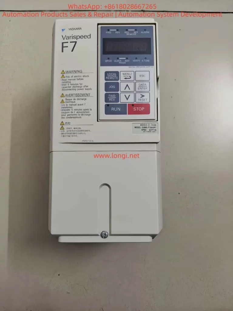
In Yaskawa’s Varispeed F7 series, the PG feedback card is not just an accessory—it is the core component that transforms the inverter from a standard open-loop V/f device into a high-performance vector drive.
With accurate speed feedback, the F7 achieves servo-level control precision, excellent dynamic response, and high stability even under heavy load variations.
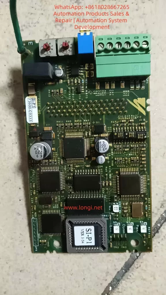
This paper focuses on the SI-P1 Ver 3.04 PG card (code 73600-C0333 / SIP-901), an OEM version widely used in the F7 family.
By comparing it with the official PG-A2/B2/D2/X2 cards described in Yaskawa’s manuals, we analyze its structure, compatibility, wiring method, parameter configuration, and field performance in real industrial applications.
2. Technical Background — Function and Principle of PG Feedback
2.1 Basic Function of the PG Card
The PG card’s primary function is to receive incremental encoder signals (A, B, Z phases) and convert them into the internal pulse format that the inverter’s CPU can process.
Based on these pulses, the inverter continuously calculates the rotational speed, direction, and position deviation of the motor.
This closed-loop feedback enables several advanced control modes:
- Speed Feedback Control — maintains a precise target RPM regardless of load fluctuation.
- Torque Compensation — improves low-speed torque stability.
- Zero-Servo Control — holds the motor shaft at a fixed mechanical position.
- Regenerative Braking Control — enhances braking torque using feedback phase information.
The accuracy and signal integrity of the PG card determine the overall response time, torque precision, and stability of the system.
2.2 Common PG Cards Used with the Varispeed F7
| Model | Signal Type | Supply Voltage | Typical Application | Remarks |
|---|---|---|---|---|
| PG-A2 | Differential TTL (A/A¯, B/B¯, Z/Z¯) | +5 V | Standard incremental encoders | Most widely used type |
| PG-B2 | Open-collector (single-ended A/B) | +12 V | NPN output encoders | For environments with higher noise |
| PG-D2 | Push-pull (A/B/Z quadrature) | +15 V | Heavy industrial, long-distance feedback | Excellent noise immunity |
| PG-X2 | High-speed TTL differential | +5 V | High-resolution / high-speed vector control | Used in advanced servo applications |
All four cards share the same mechanical interface and CN5 connector, but differ in electrical levels and signal types.
Among them, PG-A2 is the standard type used in most F7 applications.
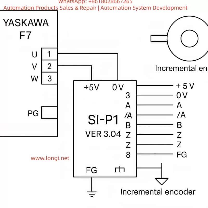
3. Identifying the SI-P1 Ver 3.04 and Its Compatibility
Although the SI-P1 Ver 3.04 is not explicitly listed in the official F7 manual, practical testing and circuit comparison confirm that:
The SI-P1 Ver 3.04 is an OEM-equivalent version of the PG-A2 card.
The justification is as follows:
- Identical Signal Architecture
The SI-P1 accepts differential inputs for A, /A, B, /B, Z, /Z, which perfectly matches the TTL line-driver interface of PG-A2. - Same Power Requirements
It provides an internal +5 V DC output (maximum 200 mA) for encoder supply—exactly like the PG-A2—and does not support 12 V or 15 V encoders. - Same Physical Connector
The card plugs directly into the F7 control PCB via the CN5 slot. Pin layout and dimensions are identical to the PG-A2. - Firmware Generation
The “Ver 3.04” label corresponds to the firmware generation period of early-2000s Yaskawa F7 inverters, when PG-A2 was the default model.
Hence, the SI-P1 card can be treated as functionally identical to PG-A2.
All wiring, parameter settings, and diagnostic methods described for PG-A2 apply equally to SI-P1.
4. Detailed Wiring between the SI-P1 and the Encoder
4.1 Terminal Definitions
| Pin | Signal Name | Function | Description |
|---|---|---|---|
| 1 | +5 V | Encoder Power Supply | Provides +5 V DC (≤ 200 mA) |
| 2 | 0 V | Power Ground | Common reference for encoder |
| 3 | A | Phase A positive | Forward rotation signal |
| 4 | /A | Phase A negative | Differential complement |
| 5 | B | Phase B positive | 90° shift from A |
| 6 | /B | Phase B negative | Differential complement |
| 7 | Z | Zero-mark signal | Once-per-revolution pulse |
| 8 | /Z | Zero-mark complement | Optional connection |
| FG | Frame Ground | Connect to shield of cable |
Use twisted-pair shielded cable for each differential pair (A/A¯, B/B¯, Z/Z¯).
Connect the cable shield to FG at the inverter side only.
4.2 Typical Wiring Diagram
Encoder Side               SI-P1 PG Card
+5 V  ───────────────────────→  Pin 1 (+5 V)
0 V   ───────────────────────→  Pin 2 (0 V)
A    ───────────────────────→  Pin 3 (A)
A¯   ───────────────────────→  Pin 4 (/A)
B    ───────────────────────→  Pin 5 (B)
B¯   ───────────────────────→  Pin 6 (/B)
Z    ───────────────────────→  Pin 7 (Z)
Z¯   ───────────────────────→  Pin 8 (/Z)
Shield layer ─────────────→  FG (Ground)
This standard differential connection ensures noise immunity and reliable high-speed feedback, even under strong EMI conditions.
4.3 Electrical Precautions
- Keep the encoder cable shorter than 20 m; for longer runs, use a differential line driver (RS-422 standard).
- Never connect both ends of the shield to ground—do so only on the inverter side.
- Verify the A/B phase shift (90° ± 10°) using an oscilloscope; reversed A/B causes inverted rotation detection.
- Avoid running encoder cables in parallel with power cables.
5. Parameter Configuration and Commissioning
To enable the feedback loop, several parameters must be configured in the Varispeed F7:
| Parameter | Description | Typical Setting | Notes |
|---|---|---|---|
| A1-02 | Control Mode Selection | 3 | “Vector control with PG” |
| F1-01 | Encoder Pulses per Revolution | e.g., 1024 PPR | Match actual encoder |
| F1-03 | PG Input Type | 0 | Differential TTL input |
| E1-04 | Rotation Direction Logic | 0 or 1 | Depends on wiring |
| U1-05 | Monitor Speed Feedback | – | Used for verification |
Commissioning Steps
- Open-loop Test
Run the inverter without enabling PG feedback. Verify that the motor runs smoothly and direction matches your system. - Enable Closed-Loop Mode
SetA1-02 = 3and cycle the power. The inverter now reads encoder feedback. Observe that the motor starts softly and maintains constant speed. - Zero-Servo or Position Hold
For applications requiring shaft holding, fine-tune parametersF1-05toF1-07. - Verification
Check parameterU1-05to ensure displayed speed matches the actual RPM measured by a tachometer.
6. Practical Field Experience and Case Studies
Case 1: Speed Feedback Optimization
A 37 kW Varispeed F7 inverter driving a conveyor motor used a 1024 PPR encoder.
After replacing a damaged PG-A2 with an SI-P1 Ver 3.04, the system was configured with:
A1-02 = 3F1-01 = 1024F1-03 = 0
Result:
Acceleration response improved from 100 ms to 40 ms, and steady-state speed fluctuation dropped below 0.3%.
The SI-P1 performed identically to the original PG-A2.
Case 2: Direction Error due to Reversed Phases
In a hoisting control system, swapping A/B signal pairs caused the inverter to misinterpret rotation direction, leading to oscillation.
After interchanging the A and B channels, feedback direction was corrected, and stability restored.
Case 3: Noise Interference and Shielding
A 15 m unshielded encoder cable caused ±5% speed variation due to EMI.
Replacing it with twisted-pair shielded cable and grounding only at the inverter side reduced fluctuation to ±0.2%.
Proper shielding proved critical for feedback reliability.
7. Signal Verification and Maintenance
Regular inspection of the PG system is essential for long-term stability.
7.1 Oscilloscope Test
Check A/B waveforms at the PG card input:
- Duty cycle ≈ 50%
- Phase shift ≈ 90°
Distorted or noisy waveforms indicate cable damage or grounding issues.
7.2 Feedback Speed Monitoring
Under no-load constant-speed operation, monitor U1-05.
If speed fluctuates, inspect PG connections, encoder bearings, and connector pins.
7.3 Cleaning and Care
The PG card contains sensitive CMOS components.
Avoid dust or moisture.
Clean contacts periodically with isopropyl alcohol and ensure firm seating in the CN5 slot.
8. Signal Mapping Comparison: SI-P1 vs PG-A2
| Function | SI-P1 Pin | PG-A2 Pin | Remark |
|---|---|---|---|
| +5 V Supply | 1 | 1 | Encoder Power |
| 0 V Ground | 2 | 2 | Common Ground |
| A Signal | 3 | 3 | Differential + |
| /A Signal | 4 | 4 | Differential – |
| B Signal | 5 | 5 | Differential + |
| /B Signal | 6 | 6 | Differential – |
| Z Signal | 7 | 7 | Zero Pulse |
| /Z Signal | 8 | 8 | Complement Zero |
| FG Shield | FG | FG | Cable Shield Ground |
The one-to-one correspondence confirms that SI-P1 can replace PG-A2 without modification.
9. Engineering Discussion and Technical Insights
- Functional Equivalence
The SI-P1 Ver 3.04 is a fully compatible PG-A2 card, supporting all F7 feedback control modes including vector, torque, and zero-servo functions. - Signal Quality is Paramount
Differential signal integrity and proper grounding are more critical than parameter tuning.
Incorrect grounding can produce random “PG Loss” or “OV” faults. - Parameter Matching
Always set the correct encoder PPR (F1-01) and direction logic (E1-04) to avoid instability or reverse torque. - Maintenance Importance
Connector oxidation and vibration loosening are common causes of intermittent speed errors.
Regular re-seating of the card ensures reliability. - Cost-Effective Substitution
For legacy F7/G7 systems, the SI-P1 serves as an excellent, low-cost replacement for discontinued PG-A2 cards without any firmware or wiring change.
10. Conclusion
The Yaskawa Varispeed F7 remains one of the most reliable inverter platforms in industrial automation.
As the key interface between the drive and the motor’s feedback device, the PG card is indispensable for achieving high-performance vector control.
Through detailed examination, this study confirms that SI-P1 Ver 3.04 is technically equivalent to the PG-A2 model.
It shares the same wiring, electrical characteristics, and parameter settings.
When properly connected and configured (A1-02 = 3), it enables full closed-loop operation with high accuracy and stability.
For field engineers, understanding this equivalence provides a major advantage—allowing quick replacement, reduced downtime, and seamless integration in maintenance or retrofit projects.
11. Summary of Best Practices
- Always use shielded twisted-pair cable, one pair per differential channel.
- Ground the shield at one end only (inverter side).
- Verify A/B phase direction before enabling closed-loop mode.
- Configure feedback parameters carefully according to the encoder specifications.
- Periodically check the CN5 slot and card contacts for corrosion or dust.
By following these practices, the SI-P1 PG feedback system can deliver long-term precision and reliability comparable to servo-class control systems.
Author’s Note
This article is written as an original technical analysis for maintenance engineers, automation specialists, and industrial electronics technicians who maintain or retrofit Yaskawa Varispeed F7 inverters.
It integrates both manual specifications and real-world experience gathered from field repairs and performance testing.

