Posted on

In-Depth Analysis of ACS880 Fault 9081 “External Fault 1”: Causes, Solutions, and Prevention Strategies

Introduction

The ABB ACS880 series of variable frequency drives (VFDs) is a high-performance solution widely utilized in industrial automation for motor control, energy optimization, and process automation. Renowned for its reliability and flexibility, it is a preferred choice across various industries. However, during operation, VFDs may encounter fault alarms triggered by internal or external factors, with fault code 9081—”External Fault 1″—being one of the more frequent issues. When this fault occurs, the VFD typically halts operation, leading to production interruptions, making swift problem identification and resolution critical.

This article draws on the ACS880 Firmware Manual (version 3AUG0509 005, released August 1, 2013) and the fault details you provided to conduct an in-depth analysis of fault 9081. It explores its causes, impacts on the system, and offers detailed troubleshooting steps, solutions, and preventive recommendations. Our goal is to equip you with a thorough understanding of this fault, enabling you to restore normal operation efficiently in practical scenarios.


FAULT 9081

1. Definition and Background of Fault 9081

According to the “Fault Tracing” section on page 299 of the ACS880 Firmware Manual, fault code 9081 is defined as “External Fault 1.” This is a protective fault triggered by an external input signal, indicating that the VFD has received a fault signal via a digital input (DI) terminal or fieldbus, suggesting a potential risk to the system. The manual specifies that this fault is closely tied to parameter 31.01 (External Fault 1 Signal Source), which allows users to designate the source of the fault signal, such as a specific digital input (DI1 to DI6) or a designated bit in the fieldbus control word.

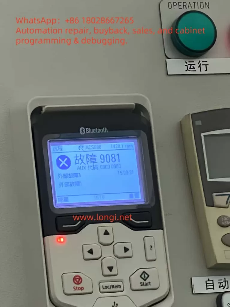
Based on the fault description you provided, the ACS880 control panel displays “Fault 9081 AUX Code 0000 0000” with “External Fault 1” noted. The auxiliary code (AUX Code) is all zeros, indicating no additional sub-fault details are available. The panel also shows an operating speed of 1420 rpm, a timestamp of 15:09:31, a “Remote” status, and an illuminated red fault indicator, confirming the device has entered a stopped state. This information serves as a valuable starting point for further analysis.

The External Fault 1 feature is designed to protect the VFD and its connected load from external anomalies. By configuring parameters, users can link the status of external devices (e.g., sensor alarms, PLC signals) to the VFD’s protective mechanisms. However, this also means that the root cause of fault 9081 may lie outside the VFD itself, in the external environment or configuration.


2. Possible Causes of Fault 9081

Drawing from the manual and real-world industrial scenarios, the causes of fault 9081 can be categorized as follows:

2.1 External Device Malfunction

The most common cause of External Fault 1 is a failure in an external device connected to the VFD. For instance, a temperature sensor detecting motor overheating, a pressure switch triggered by system overpressure, or an emergency stop button being inadvertently pressed could send a high-level signal via a digital input (e.g., DI1) to trigger the fault.

2.2 Wiring Issues

Faulty wiring at the digital input terminals is another frequent culprit. Loose, broken, or short-circuited connections can disrupt signal transmission. For example, damage to the DI1 signal line or poor contact might lead the VFD to misinterpret the state as a fault. Additionally, unshielded signal cables may be susceptible to electromagnetic interference (EMI), causing signal jitter or false triggers.

2.3 Incorrect Parameter Settings

Parameter 31.01 defines the signal source for External Fault 1. Misconfiguration, such as assigning an unused terminal (e.g., DI2) as the source or failing to match the external device’s logic state (high or low), can result in erroneous alarms. For fieldbus-triggered faults, parameters 50.01 (FBA A Enable) and 51.27 (FBA Parameter Update) must also be correctly set.

2.4 External Power or Control System Issues

Instability in the external device’s power supply or anomalies in the control logic can also trigger the fault. For example, a programming error in a PLC might cause it to send an unintended fault signal to the VFD, or voltage fluctuations in the external power supply could affect sensor operation.

2.5 Environmental Factors

Harsh industrial environments (e.g., high temperatures, humidity, dust) can impact the reliability of external devices or wiring. For instance, a sensor might malfunction under high heat, or corroded terminal connections could fail, triggering External Fault 1.


ACS880

3. Impact of Fault 9081

Once fault 9081 is triggered, the VFD executes a default protective action based on parameter 31.11 (Fault Reset Selection), typically an immediate shutdown. This stops the motor, disrupting production line continuity and efficiency. If left unresolved, the fault may lead to further issues:

  • Production Downtime: Line stoppages can result in significant economic losses, particularly in continuous production settings.
  • Safety Risks to Equipment: Failure to identify and address the external fault could lead to more severe system damage.
  • Increased Maintenance Costs: Recurring faults may require additional troubleshooting and repair time.

Thus, promptly and accurately resolving fault 9081 is essential.


4. Troubleshooting Steps

To effectively address fault 9081, follow these systematic troubleshooting steps:

4.1 Review Control Panel Information and Event Log

Begin by recording the fault details on the control panel (time, speed, status, etc.). Then, access the “Event Log” menu via the control panel or Drive Composer PC tool to review detailed fault logs. Page 300 of the manual notes that the event log stores the fault occurrence time and other parameters, aiding in identifying the trigger conditions.

4.2 Verify Parameter 31.01 Settings

Navigate to the parameter settings menu and check the configuration of parameter 31.01:

  • If set to a digital input (e.g., DI1), note the terminal and inspect its wiring and signal state.
  • If set to a fieldbus signal, verify the communication status and control word configuration.

4.3 Inspect External Devices and Wiring

Based on parameter 31.01, examine the corresponding external device and wiring:

  • Use a multimeter to measure the voltage at the digital input terminal, confirming whether it is high (typically 24V indicating a fault state).
  • Check for secure connections, ruling out looseness, breaks, or shorts.
  • Ensure signal cables are properly shielded to avoid electromagnetic interference.

4.4 Investigate External Control Systems

For fieldbus-triggered faults, inspect the PLC or upper-level controller’s program logic to ensure no erroneous fault signals are sent. Verify that communication parameters (e.g., 50.01 and 51.27) are correctly configured.

4.5 Mitigate Environmental Effects

Assess the operating environment for issues like high temperature, humidity, or dust. If conditions are adverse, implement protective measures such as installing covers or improving ventilation.

4.6 Review Historical Fault Records

Check parameter group 04 (Warnings and Faults) for the current fault (04.01) and historical records (04.02 to 04.06) to determine if the fault recurs or is linked to other issues.


5. Resolution Methods

Based on the troubleshooting results, apply the following targeted solutions:

5.1 Repair External Devices

If a sensor or switch is faulty (e.g., triggered by overheating), repair or replace the defective component to restore normal signal output.

5.2 Address Wiring Problems

Re-secure loose connections or replace damaged cables. If interference is present, use shielded cables and ensure proper grounding.

5.3 Adjust Parameter Settings

If parameter 31.01 is misconfigured, adjust it to the correct signal source or temporarily disable the External Fault function (set to “Not Used”) to isolate the issue. For fieldbus users, ensure parameters 50.01 and 51.27 are correctly set before restarting the device.

5.4 Fault Reset and Testing

Per page 299 of the manual, fault reset can be performed via the control panel, digital input, or fieldbus. Press the “Reset” key on the control panel or configure parameter 31.11 for automatic reset. After resetting, restart the VFD and monitor its operation.

5.5 Seek Technical Support

If the issue persists, page 349 of the manual recommends contacting ABB technical support. Provide the device model (ACS880), firmware version (3AUG0509 005), and fault code (9081) for professional assistance.


6. Prevention Measures and Long-Term Maintenance Recommendations

To prevent recurrence of fault 9081, consider the following preventive actions:

6.1 Regular Inspection and Maintenance

Establish a maintenance schedule to periodically check wiring terminals and external device conditions, preventing aging or damage.

6.2 Optimize Parameter Configuration

Document all parameter settings during commissioning, ensuring that 31.01 and related parameters align with the application to avoid misconfiguration.

6.3 Improve Operating Environment

Maintain suitable temperature and humidity conditions for equipment operation, reducing environmental impacts on external devices.

6.4 Enhance System Monitoring

Use Drive Composer tools or fieldbus for real-time monitoring of VFD status, enabling early detection of anomalies.

6.5 Train Operating Personnel

Provide training on ACS880 operation and fault handling to enhance staff responsiveness.


7. Conclusion

ACS880 fault 9081 “External Fault 1” is a common externally triggered fault, often caused by external device malfunctions, wiring issues, parameter errors, or environmental factors. By reviewing control panel data, parameter settings, wiring, and external devices, users can quickly pinpoint the root cause and resolve it through repairs, adjustments, or resets. Regular maintenance and optimization measures can significantly reduce fault occurrences, ensuring long-term equipment stability.

The ABB ACS880 VFD is celebrated for its efficiency and reliability, and effectively managing fault 9081 not only restores production but also maximizes its value in industrial automation. For complex cases, seeking timely support from ABB is a wise decision. We hope this article’s analysis and recommendations provide practical guidance to enhance your equipment management and production efficiency.

Posted on

TIA Portal V15 Troubleshooting Guide for Downloading to S7-1500 via Ethernet

Overview of the Problem

Users attempting to download programs to an S7-1500 PLC (CPU 1517F-3 PN/DP, firmware version V3.1, order number 6ES7 517-3FP01-0AB0) using TIA Portal V15 on a Windows system via a direct Ethernet connection from the PC’s network port to the CPU’s X2 interface (IP address 192.168.1.1) encounter issues. Symptoms: The PC can ping the PLC, but TIA Portal fails to recognize or connect to the device online, reporting an “Incompatible device” error during download attempts. Users have also tried using an SD card to write the project to the PLC, but the PLC still fails to recognize it as a loadable project. Below, we analyze potential causes in detail and provide corresponding troubleshooting and resolution steps.


S7-1500 is in a stopped state.

Potential Cause Analysis

  1. Incompatibility between TIA Software Version and PLC Firmware Version: The hardware catalog in TIA Portal V15 may not include this newer CPU model (1517F-3 PN/DP, order number 6ES7 517-3FP01-0AB0), preventing the software from correctly identifying the device. The CPU’s firmware V3.1 is a relatively high version, and if the corresponding Hardware Support Package (HSP) is not installed or TIA is not upgraded, an “incompatible device” error may occur. Additionally, Failsafe CPUs require Safety option support; failure to correctly add the safety CPU model in the project can also cause recognition errors.
  2. Mismatch Between PLC Model or Firmware Configuration and Actual Hardware: If the PLC type/firmware version configured in the project does not match the actual hardware, online comparison will fail. For example, if the project uses a non-Failsafe model (e.g., not 1517F-3 PN/DP) or a lower firmware version, TIA will treat the actual device as “incompatible.” This is especially true for Failsafe CPUs, which require the correct F-series model to connect normally. Regarding firmware versions, Siemens PLC firmware is generally downward compatible: programs can usually run if the project’s firmware version is lower than or equal to the actual CPU version, provided the software can recognize the hardware. If TIA V15 does not contain information about CPU V3.1, the hardware catalog must be updated, or the project’s CPU version setting must be changed.
  3. PG/PC Interface and Network Configuration Issues: Incorrect PG/PC interface selection or improper network configuration can prevent TIA from finding the PLC. Possible scenarios include not setting the interface to the correct local network card in TIA, the PC not having an IP address in the same subnet as the PLC, or unrelated networks not being disabled in a multi-network card environment. The most common issue is an incorrect PG/PC interface port selection: the ping command is unaffected by PG interface settings, but TIA communication requires the correct interface configuration. For example, if the PC has both wireless and wired network cards and ping uses the correct card while TIA binds to another interface, the device can be pinged but not found in TIA.
  4. Firewall or Antivirus Software Blocking Communication: The Windows firewall or third-party security software may block communication ports required by the PLC, preventing TIA Portal’s ISO-on-TCP discovery messages from reaching the PLC even if pinging is successful. If the firewall does not allow these ports, TIA may not detect the PLC or connections may be refused. Common domestic security software (e.g., 360 Security Guard, QQ PC Manager) may also disable Siemens-related services/processes, causing connection failures. For example, if the PNIOMGR process is disabled, the PLC cannot be detected. Additionally, incompatible Windows system versions or incomplete TIA installations may affect communication drivers.
  5. Misconceptions in Using Memory Cards for Downloads: When using a memory card for offline downloads, improper procedures can prevent the PLC from recognizing the project or starting up. Common mistakes include not setting the memory card as a “program card” (loadable project), simply copying engineering files instead of writing them correctly via TIA, residual old project data or incomplete files on the card, incorrect CPU startup mode settings, or not removing the physical write protection on the storage card. These issues can result in the PLC failing to recognize a valid startup project even after writing it to the card. Pay special attention to the “loadable project” option configuration; otherwise, the CPU may remain in STOP mode and fail to run the new program.

Below, we provide detailed inspection and resolution steps for each potential cause.

1. Troubleshooting and Resolving TIA Version and PLC Firmware Compatibility Issues

Cause Analysis: When TIA Portal is outdated, its hardware catalog may not include newly released CPU models or firmware versions, leading to connection failures. The 1517F-3 PN/DP (6ES7 517-3FP01-0AB0) in this example is a subsequent product, and its firmware V3.1 may have been released after TIA V15. Without installing updates supporting this CPU, TIA V15 will fail to recognize it correctly, reporting an “incompatible device” error. Additionally, Failsafe CPUs require the corresponding safety CPU model in TIA (requiring the installation of the STEP 7 Safety option); otherwise, recognition errors will occur.

Inspection Steps:

  • Check Actual CPU Information: Confirm the CPU’s actual order number and firmware version through its built-in display or TIA’s “Online Diagnostics.” For example, the CPU panel may show the model 1517F-3 PN/DP and firmware version V3.1 (as seen in user-provided photos). Record this information.
  • Check CPU Configuration in the Project: Open the “Device Configuration” in the TIA project and verify that the selected CPU model and its firmware version match the actual hardware. Ensure the order number and type are correct. If a different model is used in the project (e.g., 1517-3 instead of 1517F-3, or a different order number suffix), it must be changed. For the firmware version, TIA generally allows selecting different versions supported by the model. Check the CPU properties in the project to confirm the firmware version setting matches or is lower than the actual firmware.

Resolution Steps:

  1. Update Hardware Support or Upgrade TIA: Ensure TIA Portal has installed the hardware support package (HSP) containing the 1517F-3 PN/DP (6ES7517-3FP01-0AB0). Visit the Siemens official website to download and install the latest HSP for TIA V15. If the HSP is unavailable or the CPU model still does not appear after installation, consider upgrading the software to V15.1 or higher for native support of the new CPU. Newer TIA versions are generally backward compatible with older projects and support newer firmware.
  2. Modify the CPU in the Project to the Correct Model: In the project tree’s device view, right-click the original CPU module and select “Change Device…”. Locate 1517F-3 PN/DP in the CPU selection list and match the correct order number (note the difference between 3FP00 and 3FP01) and firmware version. For example, select 6ES7517-3FP01-0AB0 with firmware V3.1 (if V3.1 is unavailable in TIA V15, select the highest V2.X version). When changing the device, check “Retain Program” and hardware configuration to avoid losing written logic. After confirmation, the project’s CPU will update to the new model.
  3. Ensure Project Firmware Version Compatibility: For firmware version mismatches, follow the principle that the project’s firmware version ≤ actual firmware version for normal downloads. For example, a project configured with V2.6 can be downloaded to a CPU with actual firmware V3.1 and run, but new features in V3.1 will not be available. If TIA V15 can only select V2.6 and the CPU is V3.1, this is acceptable. However, if the project’s firmware version is higher than the actual version, lower the project’s version or update the PLC firmware.
  4. Install the STEP 7 Safety Option (if applicable): Confirm that TIA has the corresponding version of the Safety module installed and a valid safety programming license. If the initial project used a non-Failsafe CPU due to the lack of Safety support, install Safety support first, then replace the CPU with an F-series model and recompile the project. Failsafe PLCs can only download full-featured projects when configured as safety CPUs in the project.
  5. Attempt Download Again: After making the above changes, recompile the project hardware and try “Download to Device > All.” TIA should now recognize the compatible CPU and no longer report device incompatibility errors. If the error persists, carefully check for differences in the order number/model or consider upgrading TIA.

Note: If upgrading TIA is not possible due to objective constraints, consider downgrading the PLC firmware to a version supported by TIA (not recommended for beginners). For example, some cases involve downloading the program using a higher TIA version, downgrading the CPU hardware information, and then downloading with an older TIA version to enable connection. However, this process is complex and risky; upgrading the software to match the hardware is generally preferred.

Additionally, as a high-end model, the 1517F-3 PN/DP requires a Simatic Memory Card as load memory to run programs (S7-1500 series CPUs must have a card inserted to run; without a card, the CPU cannot enter RUN mode). Therefore, ensure that a non-write-protected SIMATIC memory card is inserted into the PLC during downloads (see the memory card section below for details). Otherwise, downloads may fail or report errors.

TIA failed to connect to S7-1500.

2. Troubleshooting and Resolving PLC Model or Project Configuration Mismatches

Cause Analysis: The hardware configuration in the project must exactly match the actual PLC type; otherwise, connection and download attempts will be rejected. For example, in this case, the CPU is a Failsafe model, but if a standard CPU is mistakenly used in the project, TIA will detect the hardware mismatch and report an “incompatible” error. Similarly, if the project’s firmware version is higher than the PLC’s actual version, download attempts will also fail (usually with a version error message). Additionally, if a project previously downloaded by a higher TIA version remains on the CPU, downloading a lower-version project with an older TIA version may cause conflicts, preventing the PLC from recognizing the new project or reporting version inconsistencies. In such cases, the PLC may not recognize the new project or report errors.

Inspection Steps:

  • Open the project’s device configuration and verify that the station nameCPU model, and interface configuration match the physical device. Focus on checking whether the correct 1517F-3 PN/DP model is selected (not another model), whether the interface (X2) IP setting is 192.168.1.1, and whether the subnet mask matches the actual network.
  • Check the CPU properties for the firmware version setting (if selectable). Ensure it is not higher than the actual PLC firmware. If the project’s firmware version is lower, it is generally acceptable, but you can adjust it to match the actual version as needed to eliminate warnings. Right-click the CPU in the project device and select “Properties” to view the currently configured version and order number, which can be compared with the actual PLC information.
  • If a previous download attempt was unsuccessful, residual project data may remain on the PLC’s memory card, causing conflicts during subsequent downloads. Check the CPU display or online diagnostics for information on residual projects or error states (e.g., Memory card LED or maintenance light).

Resolution Steps:

  1. Correct the CPU Model and Order Number: If the project’s CPU model is incorrect (e.g., 1517 instead of 1517F), follow the previous steps to change it to the correct 1517F-3 PN/DP model. Ensure the order number suffix matches the device (e.g., FP01 vs. FP00). After making changes, regenerate the hardware and software compilation.
  2. Adjust the Firmware Version Configuration: In the project, set the CPU firmware version to no higher than the actual version. TIA allows switching firmware versions within a certain range (right-click the CPU > Change Version, if available). For example, if the actual PLC is V3.1 and TIA V15 supports up to V2.6, set the project’s CPU version to V2.6. The program can still run, but new features in V3.1 will not be available. If TIA has installed an HSP supporting V3.x, select V3.1 to match exactly.
  3. Ensure Consistent Project and Station Names (generally does not affect downloads, but recommended for consistency): Ensure that the project’s PLC station name does not conflict with the PLC’s default name, or set a unique name for the CPU as needed and select the appropriate option during download (overwrite the device’s name or retain the device’s name).
  4. Clear Old Project Data from the PLC: If previous download attempts have left newer version projects or incomplete data on the memory card, clear it first. Method: Format the memory card via the CPU panel or, with the CPU in STOP mode, select “Format Memory Card” in TIA’s “Online & Diagnostics > Functions” to clear the card’s project data. Do not format the SIMATIC card using Windows; only delete project files within it, as formatting with Windows will render the card unusable. Alternatively, remove the memory card, use a PC card reader to delete project files in the SIMATIC.S7S directory (to clear old projects), then reinsert the card and reset the CPU power to prepare it for a clean download.
  5. Redownload the Project: After ensuring the project configuration matches the hardware and the PLC’s memory card is clean, try downloading again. In TIA, select “Download to Device (Software + Hardware)” and check “Selected Stations” for the current project’s CPU. TIA should now detect the correct device type. If a confirmation dialog appears (e.g., “No project information on the device, load as new station?”), select Load as New Station. During the download, if version warnings appear, follow the prompts and select “Continue” (if it is a firmware upgrade prompt, generally select “No” to retain the current firmware). After completion, a successful download message should appear.
  6. Check the Running State: After downloading, observe whether the PLC enters RUN mode. If it remains in STOP and displays an “incompatible” message, there may still be configuration mismatches. Use TIA’s “Online > Accessible Devices” to scan and see if the CPU is correctly identified with its firmware. If the device is marked red and labeled “incompatible” in the scan results, the project configuration still does not match the device, requiring you to recheck the above steps.

Note: When a project downloaded by a higher TIA version exists on the PLC, it may leave version information on the memory card, preventing a lower TIA version from directly overwriting it. This is why downloading a V16 project and then attempting to download with V15 fails. Clearing the memory card or formatting it resolves this issue. Therefore, in environments with multiple TIA versions, it is crucial to keep the TIA version consistent with or higher than the project version on the PLC. If you must downgrade the project version, first delete the newer version project data on the PLC before downloading the lower-version project.

3. Troubleshooting and Resolving Network Connection and PG/PC Interface Settings

Cause Analysis: Improper network parameter configuration is a common yet often overlooked cause. Although users can ping the PLC, this does not guarantee proper TIA connection. Common issues include an incorrectly selected PG/PC interface, incorrect IP address/subnet mask settings, conflicts from multiple network cards, or interference from switches or network devices. The ping command typically uses the operating system’s routing to automatically select the network interface, while TIA communication requires sending proprietary protocols through its configured PG interface. Therefore, selecting the wrong interface can result in a situation where the device can be pinged but not found in TIA. Additionally, if the PC and PLC are not in the same subnet or the gateway is unreachable, the device cannot be discovered.

Inspection Steps:

  • IP Address and Physical Connection: Confirm that the PC’s IP settings are in the 192.168.1.x subnet (not 192.168.1.1 to avoid conflicts with the PLC) with a subnet mask of 255.255.255.0. Ensure that the Link light on the PC’s network port connected to the PLC is solidly lit. The Profinet green light (Link) on the PLC’s X2 interface should also be lit, indicating a physical connection. If a switch is used, check its indicator lights for normal operation. For testing, connect the PC directly to the PLC to rule out issues with intermediate devices.
  • PG/PC Interface Settings: In TIA Portal, open “Set PG/PC Interface” or click the PG/PC interface icon at the bottom of the software to view the selected interface. Choose the actual network card’s TCP/IP interface used (e.g., “PN/IE -> Intel(R) Ethernet … (192.168.1.x)”). Do not select virtual network cards such as those for PLC simulation or VMware if they are not in use. If multiple interfaces are present, try disabling unused network adapters to ensure TIA binds to the correct card.
  • Accessible Devices Scan: In TIA, select “Online > Accessible Devices”, choose the corresponding network card interface, and click “Update”. Check if the PLC and its IP are listed. Ideally, it should display information such as “CPU 1517F-3 PN/DP … IP=192.168.1.1 … Firmware V3.1”. If the list is empty or the device is not found, it may be an interface/firewall issue. If the device is found but marked red as incompatible, return to the previous model matching issue.
  • Third-Party Network Environment: If non-standard switches/routers are used, confirm they are not blocking Profinet DCP broadcasts. Profinet device discovery relies on the DCP protocol, which may not work if the switch does not support it. For testing, connect the PC directly to the PLC to rule out switch-related issues.

Resolution Steps:

  1. Configure Correct IP Settings: Set the PC’s network card IPv4 address to the same subnet as the PLC (e.g., 192.168.1.100) with a subnet mask of 255.255.255.0. The gateway is not required (or can be set to 192.168.1.1). After setting, ping the PLC IP again to confirm connectivity.
  2. Set the PG/PC Interface: In TIA, select “Online > Set PG/PC Interface” and choose the “TCP/IP -> Local Network Card Name (PN/IE)” option. Ensure the IP address displayed matches the PC’s recently set address. If unsure, select the interface corresponding to your PC’s IP in the interface options. Apply the settings and restart TIA’s device scanning function. With the correct interface settings, TIA should now detect the PLC as easily as connecting to a regular network device. If the wrong port was previously selected, the device should now be found in the scan.
  3. Resolve Network Adapter Conflicts: If the PC has multiple networks (e.g., WiFi and wired), disable unused adapters to prevent TIA from confusing routing. This is especially important in VMware or other virtual network environments, where you must specify bridging to the correct physical network card. In virtual machines using TIA, configure the virtual network to bridge the physical network card and select the corresponding virtual network card interface in TIA. Additionally, disable the host firewall if necessary. Ensure that only one active network is used for PLC communication.
  4. Search Again or Connect by Specifying IP: After adjusting the settings, refresh the “Accessible Devices” list in TIA, which should now display the CPU. If the device is still not automatically detected, try manually specifying the IP address for connection in the TIA download dialog: In the download window, click the dropdown arrow next to “Show all accessible devices” and enter 192.168.1.1 in the address bar before pressing Enter. This forces TIA to attempt connecting to the PLC at that IP. In many cases, as long as the network and interface are correct, this step will find the device and allow downloading to proceed.
  5. Check for Special Network Factors: If connectivity issues persist, consider whether other software on the computer is occupying ports or filtering traffic. For example, some VPN clients, firewall policies, or group policies may restrict PN port 102 communication. Use the Windows command netstat -ano | find "102" to check if the port is in use. If necessary, test connectivity on a different computer to determine if the issue is environment-specific.
  6. Ensure No PLC IP Address Conflicts: Confirm that no other device on the network is using the 192.168.1.1 address. Although pinging is successful, it is possible to ping a different device (this can be ignored for direct connections). If multiple PLCs or HMIs are on the network, ensure they all have unique IP addresses.

Note: Ping connectivity only indicates that the ICMP protocol is working, but TIA downloads use the S7 protocol (TCP port 102, etc.). Therefore, it is essential to correctly configure the PG interface and disable the firewall (see the next section) to complete S7 communication. Additionally, Profinet device discovery uses DCP broadcasts, which will not work across subnets or through routers. For cross-subnet downloads, UDP forwarding or direct IP specification methods are required on the router. In most cases, placing the PC and PLC on the same subnet resolves these issues.

4. Troubleshooting and Resolving Firewall and Security Software Issues

Cause Analysis: The Windows firewall and third-party security software may block communication ports required by TIA to access the PLC. A typical manifestation is successful pinging but failure to detect or download from TIA. When the firewall is enabled and does not allow Siemens-related ports, local network connections may be blocked. TIA Portal primarily requires TCP port 102, UDP port 48879, and the DCP protocol for device discovery. If the firewall blocks these, TIA will report connection timeouts or fail to detect devices. Additionally, some domestic antivirus software (e.g., 360 Security Guard, QQ PC Manager) may disable Siemens background services/processes (such as PNIOMGR, S7DOS Service) to optimize the system, causing communication failures. Therefore, both firewall and antivirus software impacts must be considered.

Inspection Steps:

  • Firewall Status: Open “Windows Defender Firewall & Network Protection” and check if the firewall is enabled for the current network (domain, private, or public), especially in domain environments where policies may be strict. Try temporarily disabling the relevant firewall and then search for devices in TIA to see if the PLC can be detected. If connectivity is restored immediately after disabling the firewall, the firewall is likely blocking communication.
  • Security Software Impact: Check if third-party antivirus or optimization software is installed on the system. These programs may prevent certain services from starting. Open Task Manager or the Services list and look for services with “Siemens” or “S7” in their names, such as “SIMATIC IEPG Help Service” or “SIMATIC S7DOS Service”, and ensure they are running. If any are not running, try starting them manually. Then, check if the security software’s “startup optimization” feature has disabled the PNIOMGR.exe process. This process is crucial for Profinet device management; if disabled, the PLC cannot be detected. If blocked, add it to the security software’s trust list or restore its startup.
  • Port Testing: Use Windows PowerShell’s Test-NetConnection -ComputerName <PLC_IP> -Port 102 command to test port connectivity, or use third-party tools (e.g., TCPing) to test whether the PLC’s TCP port 102 is reachable. If the port is unreachable despite successful pinging, the firewall is likely blocking it.

Resolution Steps:

  1. Disable the Firewall for Testing: To quickly verify, temporarily disable the Windows firewall (for both private and public networks) in the Control Panel’s Windows Defender Firewall settings. Then, retry connecting with TIA. If connectivity is restored, add exception rules for Siemens applications in the firewall instead of leaving it disabled. Open the firewall’s “Allowed apps” settings and ensure TIA Portal and related rules (e.g., “SIMATIC Manager”) are checked, allowing access to required ports (TCP 102, UDP 48879, etc.). For Profinet Discovery, you can also allow the “Profinet Discovery” protocol in the firewall’s advanced settings. After adding rules, re-enable the firewall and observe if connectivity is maintained.
  2. Adjust or Uninstall Security Software: If using 360 Security Guard, Huorong, QQ PC Manager, or similar software, try temporarily exiting or uninstalling them and then test connectivity. Many cases show that third-party security software secretly blocks industrial communication. If confirmed as the cause, add TIA Portal to the software’s trust list or disable its network protection module. In 360’s “Optimization Accelerator,” restore any disabled Siemens-related services/processes (e.g., if PNIOMGR is disabled, re-enable it in the startup items and restart the computer). Ensure the PNIOMGR process is running (located in C:\Program Files\Common Files\Siemens\Automation\Simatic OAM\bin by default; can be started manually).
  3. Check System Policies: On some company computers, group policies may disable RPC services or apply AppLocker rules that block TIA components. These can also affect communication. Try installing TIA on a clean personal computer and connecting it directly to the PLC for testing to determine if the issue is environment-specific. If connectivity is restored on a different PC, work with the IT department to restore default firewall rules or disable unnecessary security policies on the original PC.
  4. Network Isolation Devices: If firewalls or routers are present between the PC and PLC, configure them to allow relevant traffic (e.g., hardware firewalls must allow UDP 67, 68 for DCP and TCP 102). If unsure, the simplest method is to connect directly or use a simple switch for direct connection to avoid interference from network
Posted on

S7-1500 Memory Card Offline Programming Process and Analysis of “Empty Card” Issues

I. Correct Process for Offline Programming of S7-1500 Memory Cards in TIA Portal

In TIA Portal, you can directly download a compiled project offline to an SIMATIC memory card for the S7-1500, creating a “program transfer card” for loading programs onto the PLC without an internet connection. The recommended steps are as follows:

Hardware Preparation: Use an official Siemens SD card reader and insert an SIMATIC memory card (e.g., 6ES7 954-8LC04-0AA0) into the computer’s USB port. Ensure the card is not write-protected (slide the side switch to the unlocked position). TIA Portal will automatically recognize the card reader.

Memory Card Identification: In the TIA Portal project tree, expand the “Card Reader/USB Memory” node to view the corresponding memory card drive (e.g., “(G:) SIMATIC MC [Program]”). If it does not appear, refresh it via the menu “Online > Display SIMATIC Card Reader”.

Download Project to Memory Card: Select the CPU station in the project tree (e.g., “PLC_1 [CPU 1516-3 PN/DP]”) and drag it to the memory card drive node. Release the mouse, and TIA Portal will prompt a download dialog. Compile and confirm the write operation as instructed. Alternatively, use the menu option “Online > Write to Memory Card”.

Completion of Writing: If the project compiles and writes successfully, TIA Portal will indicate completion. The memory card now contains the program data files for PLC startup. Safely eject the card from the reader, insert it into the target S7-1500 CPU slot, and power on or reset the CPU to load the program from the card.

Additional Note: The drag-and-drop method generates an S7_JOB.S7S (or .SYS) file and a “SIMATIC.S7S” project folder on the memory card, containing all user program data for the PLC. This allows for offline upgrades without an online PLC connection. If TIA Portal is unavailable, generate the project to a PC folder or USB drive first, then transfer it to the memory card.

6ES7 517-3FP01-0AB0

II. Possible Reasons for Controller Identifying Memory Card as Blank

When an S7-1500 CPU displays “Empty card,” it means no valid user program has been detected on the card. For example, the memory card type is identified as “Empty card,” with 0 used space, as shown below.

An S7-1517F CPU displays the memory card type as “Empty card,” indicating no valid program data has been detected.

Common causes include:

Unsuccessful Project Data Writing: If the offline programming process is not completed correctly (e.g., compilation without “Write to Memory Card” execution, or interruption during download), the card may lack the S7_JOB.S7S file and “SIMATIC.S7S” folder. The CPU will then treat the card as empty. Interruptions (e.g., network/power failures) can result in incomplete project data, preventing CPU recognition.

Memory Card File System or Structure Issues: SIMATIC memory cards for S7-1500 use the FAT32 format with pre-installed hidden system files. Non-official formatting, accidental deletion of hidden files, or file system errors can prevent CPU recognition. For instance, hidden “LOG” and “crdinfo.bin” files are essential for card identification; their deletion or corruption may render the card unrecognizable, causing the CPU to treat it as uninitialized and blank.

Project-CPU Incompatibility: Although not directly causing an “empty card” display, if the card contains a higher-version project unsupported by the CPU firmware or inconsistent project data, the CPU may ignore the card contents. For example, a project version higher than the current TIA Portal engineering version may prevent loading (though the CPU displays an empty card, it actually does not recognize the program). Resolving version mismatches requires firmware upgrades or project regeneration.

Hardware or Operational Factors: A damaged or poorly connected memory card can also cause reading failures. Ensure the card is not write-protected; otherwise, while the CPU can read the program, TIA Portal will reject writes (write protection does not cause a blank card but prevents program updates).

Note: According to Siemens official manuals, an “empty memory card” lacks the user program job file (S7_JOB.S7S) and project data folder (SIMATIC.S7S). When detecting an empty card, the S7-1500 CPU will attempt to copy its internal load memory contents to the card (and clear the internal memory) by default or remain unchanged if automatic copying is prohibited. If the CPU also lacks a program, inserting an empty card will leave it without a user program to run, necessitating normal downloads or offline programming as described.

III. Methods to Confirm Valid Program on Memory Card

To ensure the memory card contains a valid PLC program, verify the following:

Check Memory Card File Structure: Use Windows Explorer to open the memory card drive via the reader and check for the presence of the S7_JOB.S7S file and “SIMATIC.S7S” folder in the root directory. The S7_JOB.S7S file contains job instructions for CPU startup, while the “SIMATIC.S7S” folder holds compiled STEP 7 program block data (OBs, DBs, etc.). These files are essential indicators of successful TIA Portal programming; their absence indicates an unsuccessful write.

TIA Portal Property Check: Right-click the identified memory card drive in the TIA Portal project tree (e.g., “(F:) SIMATIC MC [Program]”) and select “Properties” to open the “Memory Card” dialog. Confirm the card type is “Program,” the file system is FAT32, and the used/available storage capacity matches the project size. For example, a 4MB card may show increased usage after programming. If the card remains blank or capacity is unchanged, the write operation likely failed, requiring a retry.

In TIA Portal, viewing SIMATIC memory card properties reveals the card type as “Program” and the file system as FAT32. If a project has been written, the card’s capacity usage should increase accordingly.

CPU Display and Status: Insert the card into the CPU and power it on. Observe the CPU display and indicator lights. Normally, the CPU should recognize the card as a “Program Card” and enter RUN mode. If it displays “Empty card” or remains in STOP mode, the program did not load successfully. Check the CPU panel’s “Memory Card Information” for project name/version (if available) to confirm CPU recognition.

Verify Operational Effect: Finally, observe the CPU’s RUN mode and controller behavior to indirectly confirm program loading. For example, if the program contains startup OBs or output logic, check the corresponding output states after power-on or use TIA Portal’s online monitoring (if connected) to verify CPU program blocks match the offline project.

Tip: SIMATIC memory card program data is encrypted and cannot be directly identified from file contents. However, file existence and structural integrity are sufficient to confirm successful programming. Always safely eject the memory card after writing to prevent incomplete writes or file corruption.

empty card

IV. Memory Card Recovery and Reprogramming Methods

If the memory card is still recognized as blank after insertion into the CPU, take the following steps to restore functionality:

Format via CPU Display: Switch the CPU to STOP mode and access the “Format Memory Card” function in the CPU’s LCD menu (usually under “Functions”). Confirm execution to clear all user data and rebuild the necessary system file structure. This method requires no additional software and is suitable for quick on-site card clearing. After formatting, the display should indicate card initialization.

Format via TIA Portal: Connect to the target CPU in TIA Portal (or via “Accessible Devices”) and open the “Online & Diagnostics” window. Navigate to “Functions > Format Memory Card,” click “Format,” and confirm. This restores the card to factory-blank status (retaining essential hidden files). After formatting, reprogram the card following the correct offline process.

Manual Cleanup via PC Reader: Insert the card into the reader and connect it to the computer. Open the card drive in Windows Explorer and delete the S7_JOB.S7S file and “SIMATIC.S7S” folder (and any other folders like DataLogs, Recipes, if present). Note: Do not format or delete invisible system hidden files (e.g., “LOG,” “crdinfo.bin”). After manual cleanup, the card becomes blank and can be reprogrammed via TIA Portal.

After any recovery step, reprogram the project data onto the memory card following the correct offline process. Ensure no old project residues remain on the card to prevent confusion with new data. If the card is suspected to be faulty (e.g., physical damage or end-of-life from repeated writes), replace it with a new SIMATIC memory card.

V. Siemens Official Guidelines on Programming Operations and Recognition Rules

Siemens provides detailed official documentation on SIMATIC memory card usage:

TIA Portal Offline Programming Process Guide: Siemens Industrial Support Center’s FAQ (Document ID 48711409) explains how to generate and store project data on S7-1200/1500 memory cards for offline program transfer to the CPU. It covers three methods: using a card reader, USB drive, or local folder, and describes the resulting file structure (including S7_JOB.S7S and SIMATIC.S7S).

Memory Card (Program Card) Usage Rules: The S7-1500 series user manual outlines memory card behavior as load memory (program card). For example, inserting a program card prompts the CPU to replace its internal program with the card’s program at startup and requires the card to remain in the CPU as external load memory. Removing the program card during operation stops the CPU and triggers an error due to the missing program. Regarding empty cards, the manual states that if an empty card is detected and automatic copying is not prohibited, the CPU copies its internal program to the card at power-on, then clears the internal memory. The CPU must then start from the card. These mechanisms govern how the S7-1500 determines if a memory card contains valid programs and takes appropriate actions.

Posted on

Troubleshooting Schneider ATV310 Drive Displaying –06 and Failing to Start or Run

1. Introduction: Symptoms and Background

In Schneider Electric’s Altivar ATV310 variable frequency drive (VFD), users may occasionally encounter the code --06 displayed on the integrated 7-segment LED screen. This condition is often accompanied by the motor being unable to start or respond to frequency commands. Although this may look like a fault, --06 is not an error code, but rather a status indication representing a special operating condition—usually “Freewheel Stop.”

This article explains the meaning of --06, identifies common causes, and walks you through practical steps to resolve the issue and restore normal operation.

--06

2. What Does --06 Mean?

The display code --06 on the ATV310 is an operational status code indicating that the drive is currently in Freewheel Stop mode, meaning output is disabled and the motor is freely coasting. This state is not caused by a fault but is often the result of control logic, input conditions, or communication states.

Other common drive statuses include:

  • --00: Drive ready (no run command)
  • --01: Fast stop
  • --06: Freewheel stop

While the drive is in --06, no output frequency is generated—even if run commands are issued—until the condition is cleared.


3. Common Causes of --06 Status

Several typical reasons could trigger the --06 state:

🟠 a. Logic Input Assigned to Freewheel Stop

If a digital input (e.g., LI1–LI4) is assigned to the Freewheel Stop function and is active, the drive will enter --06.

🟠 b. Incorrect Run Command in 2-Wire or 3-Wire Mode

  • In 2-wire mode (P201 = 2C), the drive needs a level-type run signal on LI1.
  • In 3-wire mode (P201 = 3C), a pulse-style start and stop logic is used.
    If wiring or configuration mismatches occur, the drive may fall into --06.

🟠 c. Serial Communication Without Proper Commands

If you’re controlling the drive via Modbus or RS-485, and the master does not send a valid start command (bit 0x6 = 1), the drive enters --06.

🟠 d. Analog Input Loss or Signal Drop

When using 4–20 mA input for speed control, a loss of input signal could trigger a fallback to freewheel stop.

🟠 e. Stop Button or Remote Stop Triggered

If the STOP key on the panel or an external STOP command is active, the drive may enter --06.

🟠 f. Residual State After Power Cycle

Sometimes the drive reboots directly into --06 if the prior control signals remain unchanged.


4. Step-by-Step Troubleshooting and Recovery

✅ Step 1: Check Control Mode and Logic Inputs

  • Confirm the control mode: P201 (2-wire/3-wire/serial).
  • Check P202, P203 for proper assignment of RUN/STOP logic inputs.
  • Use monitor mode (parameters 800–811) to observe input signal status.

✅ Step 2: Inspect Physical Inputs

  • Check if any logic inputs (e.g., LI1) are incorrectly triggered.
  • Look for short circuits, faulty switches, or wiring issues.

✅ Step 3: Check Analog/Serial Communication Settings

  • For analog control, verify AI1 input signal and scaling.
  • For Modbus, confirm that the master is sending the appropriate control word (bit 0x6 = 1).

✅ Step 4: Clear the Freewheel Stop and Restart

Option 1: Via Panel Navigation

  • Press ESC or MODE on the HMI.
  • Exit back to the main screen, wait for rdY (ready) to appear.

Option 2: Power Cycle

  • Power off the drive for 10 seconds, then power it back on.
  • The screen should return to --00 or rdY.

Option 3: Reassign Input Functions

  • Use P202 to change logic input function from Freewheel Stop to an unused input.
  • Set unused inputs to No Function (typically code 00).

ATV310

5. Ensuring Stable Operation After Recovery

After returning to normal status, take the following steps to avoid future issues:

  • ✅ Reassign logic inputs only when needed.
  • ✅ Avoid assigning STOP or Freewheel functions to frequently active lines.
  • ✅ Add debounce and safety logic in PLC/HMI control.
  • ✅ Enable fault auto-restart (parameter 602.0 = 01).
  • ✅ Use clear feedback loops if controlling via communication protocol.

6. Summary Table

StepDescription
Identification--06 is Freewheel Stop, not a fault
AnalysisCheck logic input functions, run mode, communication
ResolutionNavigate panel, correct wiring or reset power
OptimizationAdjust input definitions and enable self-recovery logic

7. Conclusion

The --06 display on a Schneider ATV310 is a common condition that can interrupt motor operation but is not an error. With proper diagnosis—by inspecting control signals, input assignments, or communication—this state can be quickly cleared.

Once resolved, implementing preventive logic configuration and enabling smart restart strategies can ensure robust and continuous drive performance in both standalone and automated systems.

If issues persist, contacting Schneider’s technical support or reviewing the full parameter manual is recommended.

Posted on

Toshiba VF-PS1 Inverter Stuck at “ELL0” with All LEDs Lit – Root Causes and Solutions

In the field of industrial automation, inverters play a crucial role in driving motors and optimizing energy efficiency. The Toshiba VF-PS1 series is known for its reliability and versatility across a wide range of applications such as manufacturing, HVAC systems, and water treatment. However, during a recent on-site startup, an unusual issue occurred: the inverter powered up and the screen continuously displayed “ELL0”, while all indicator LEDs on the operation panel (RUN, Hz, %, MODE, EASY, etc.) were fully lit and unresponsive. The device failed to transition to its normal frequency display or any operational mode.

ELL0

This article analyzes this abnormal behavior in depth, including its possible causes, technical diagnostics, and step-by-step troubleshooting solutions based on real-world experience. It aims to provide valuable insight for field engineers and maintenance professionals dealing with Toshiba VF-PS1 inverters.


1. Interpreting the “ELL0” Message

The first observation is that the code “ELL0” is not listed in the VF-PS1 manual’s error or alarm code tables. Most standard error codes for Toshiba inverters follow formats like E-xx (e.g., E-10 for analog input error, E-11 for sequence error) or Errx (e.g., Err4 for CPU fault).

Given this, “ELL0” is not a known error code but likely a simplified or stylized display of a word. Considering the limitations of seven-segment or basic LCD panels, the letter “H” may be rendered as “E”, resulting in the word “HELLO” being shown as “ELL0.”

In fact, several other Toshiba inverter series such as VF-S15 are documented to display “HELLO” during startup as a friendly greeting. While VF-PS1 manuals do not explicitly mention this, it is highly plausible that “ELL0” is simply the inverter saying “HELLO” at startup.

Conclusion: “ELL0” is not an error, but a startup message indicating the inverter is initializing.

However, this message is only meant to appear for a few seconds. If the inverter remains stuck on this screen for an extended time, and the display does not change to frequency output, “STOP,” or any other active status, then the system is failing to complete its initialization sequence.


2. Why Are All the LEDs Constantly Lit?

Electronic devices often illuminate all LEDs during the power-on self-test (POST) to confirm the panel is functional. The VF-PS1 has multiple LEDs on its keypad including RUN, Hz, %, MODE, and EASY.

In a normal power-up, these LEDs briefly flash and then only relevant indicators remain lit based on status:

  • In standby: only Hz and power indicators
  • In run mode: RUN LED is lit
  • During fault: alarm LED or fault code appears

⚠️ If all LEDs remain lit indefinitely, this suggests the system has not successfully exited the boot process. When combined with a stuck “ELL0” display, it is a clear sign the inverter is failing to transition to operational state.


VFAS1

3. Possible Technical Causes of the Fault

After analyzing the inverter’s architecture and behavior, the following are the most probable causes for this issue:

1. Main Control Board (CPU) Failure

The control board houses the CPU, EEPROM, and firmware that drive the entire system. If any of these components fail (e.g., due to static discharge, aging, memory corruption), the inverter may not proceed past startup, effectively freezing on the “HELLO” message.

2. Internal Control Power Supply Instability

Toshiba inverters typically generate low-voltage DC internally (e.g., 5V or 24V) to power logic and display. If these voltages are unstable due to aged capacitors or faulty switching circuits, the system may repeatedly attempt to initialize and fail each time.

3. Operator Panel Communication Failure

The panel communicates with the inverter’s main board through a connector or internal bus. If this link is disrupted—due to loose cables, damaged connectors, or panel PCB faults—the display might not receive valid data and remain stuck at its default state.

4. External Expansion Modules Interfering

If optional communication or I/O modules (e.g., Profibus, DeviceNet, or analog expansion) are connected and one of them malfunctions, it may prevent the system from passing its full self-test. This can effectively freeze the inverter before entering active status.

5. Corrupt Parameters or Firmware

Sudden power loss during write operations or faulty parameter resets may corrupt memory. If the inverter firmware or configuration table cannot initialize correctly, the inverter may hang during startup without even reporting an error.


4. Troubleshooting Steps and Solutions

The following field-tested steps may help restore the inverter to normal operation:

Step 1: Perform a Full Power Reset

  • Power off the inverter completely
  • Wait at least 15 minutes to allow internal capacitors to discharge
  • Re-energize and observe whether the display changes from “ELL0” to frequency display or run status

Step 2: Inspect the Panel Connection

  • If the keypad is external, check cable integrity and re-seat connections
  • If it’s an internal panel, check the physical contact to the main board
  • A faulty keypad may need replacement

Step 3: Remove Optional Modules

  • Disconnect any communication modules, expansion I/O boards, or external terminals
  • Reboot the inverter in minimal configuration
  • If the device initializes successfully, one of the peripherals is likely faulty

Step 4: Check Power Input and Control Voltage

  • Measure voltage at R/S/T terminals; confirm it’s within rated range and phase-balanced
  • If possible, measure internal low-voltage DC power (e.g., 5V or 24V) on the control board to ensure stability

Step 5: Attempt Parameter Initialization (if possible)

  • If the panel becomes responsive after reboot, consider resetting parameters to factory defaults
  • This may clear out any corrupt settings

Step 6: Consider Control Board Replacement

  • If none of the above steps restore operation, it’s likely the control board is faulty
  • Repair or replacement of the control PCB is required
  • Only qualified technicians should attempt internal board-level diagnostics

5. Preventive Measures

To avoid similar issues in the future:

  • Avoid frequent rapid power cycling, which can corrupt firmware or cause startup errors
  • Use surge protection and voltage stabilizers to ensure clean input power
  • Periodically inspect cooling fans and capacitors, which degrade over time
  • Only perform parameter resets under safe, powered-down conditions

6. Final Thoughts

While the appearance of “ELL0” on a Toshiba VF-PS1 inverter display might seem alarming at first, it is not inherently a fault code, but rather a welcome message (“HELLO”) that appears during power-up.

However, if the inverter remains stuck on “ELL0” and all panel LEDs stay on, it indicates a serious problem—typically that the inverter failed to complete its startup self-test. Common causes include CPU failure, unstable internal power, communication breakdown with the panel, or peripheral errors.

Technicians are advised to follow a structured troubleshooting process, starting with simple checks and escalating to control board diagnostics if necessary. If the issue persists and the inverter cannot be brought into operational state, professional service intervention or control board replacement is the likely solution.


Posted on

Detailed steps for configuring the MT500 frequency inverter to “display the actual rotational speed in RPM”:

Goal: make the MT 500 drive’s LED keypad show actual motor speed in r/min (RPM).
Assumptions: drive is stopped, control source = keypad.

1 . Enter the parameter list (“Standard menu”)

ActionExpected displayComment
Press ESC repeatedly from the normal monitor screen‑bSC‑“Basic / Standard menu” root 
Press ENTERP00.00You are now at the parameter index level

Tip: ESC moves up one level; ENTER confirms / goes down.


MT500

2 . Fill in the motor name‑plate data

(needed so the drive can translate Hz → RPM correctly)

2‑a  Locate P11.05 Rated frequency
  1. While P00.00 is shown:
    • Press SHIFT until the left‑most digit blinks.
    • Tap UP until that digit becomes 1 → display reads P10.00.
    • Press SHIFT once to move the cursor to the last digit; UP once → P11.00.
    • Tap UP five more times → P11.05.
  2. Press ENTER – the current value (e.g. 50.00) blinks.
2‑b  Edit the value
  • Use SHIFT to select the digit; UP / DOWN to change it.
  • Press ENTER to save. Display flashes End, then returns to P11.05
2‑c  Repeat for P11.06 Rated speed
  • Navigate to P11.06 the same way; enter the motor’s rated RPM; ENTER to save. 

3 . (Optional) Run auto‑tune P11.10

ActionDisplay
Go to P11.10, ENTERvalue blinks (default 0)
UP1 (stand‑still tune) or 2 (rotating tune)
ENTER to store → EndAuto‑tune will start the first time you press RUN afterwards 

4 . Switch the display unit from Hz to RPM — P21.17

ActionExpected display
Press ESC twice to get back to P00.00; jump to P21.17P21.17
ENTER – value blinks (0 = Hz)
UP once → 1 (= RPM)
ENTER to save → EndThe Hz and A LEDs now light together, meaning the keypad shows RPM 

5 . See the live speed

  1. Press ESC until the normal monitor screen returns.
  2. The default monitored variable is r27.00. Because P21.17 = 1, its value is already in RPM. 
  3. Press SHIFT (>>) to step through other view pages if needed; the Hz + A LEDs confirm the unit remains RPM.

mt500-7r5-t4b

6 . (Optional) Show only speed on the monitor page

If you dislike the rotating multi‑page display:

  1. Navigate to P21.11 (run‑mode sequence) and set it to 0001.
  2. Do the same for P21.12 (stop‑mode sequence) if desired.

Now the keypad will lock onto a single page that shows r27.00 in RPM.


Quick trouble‑shooting

SymptomLikely causeFix
Still shows HzP21.17 not saved, or you are viewing another variableRe‑enter 1; check Hz+A LEDs
RPM reading off by a lotWrong name‑plate data or no auto‑tuneRe‑check P11.05 / P11.06, run P11.10
Cannot enter parametersUser lock activeEnter password in P00.00 or restore defaults

Ultra‑short recap

  1. ESC‑bSC‑ENTER → parameter list.
  2. Set P11.05 (rated Hz) & P11.06 (rated rpm).
  3. (Option) P11.10 = 1 or 2, auto‑tune after RUN.
  4. P21.17 = 1 → units = RPM.
  5. Monitor page now shows real speed; enjoy!
Posted on

Troubleshooting Guide for OH Faults in GTAKE GK820 Series Inverter

In the field of industrial automation, frequency inverters play a critical role in motor control. The stable operation of these devices is vital to maintaining production efficiency. The GTAKE GK820 series inverter, known for its performance and reliability, is widely used in various mechanical equipment. However, during operation, users may encounter OH-series fault codes (such as OH1, OH2, OH3), which indicate issues related to overheating protection. Understanding the causes and countermeasures for these faults is essential for maintenance and troubleshooting.

1. Overview of OH Fault Codes

OH1

The OH-series fault codes on the GK820 inverter signify temperature-related issues that trigger automatic protection mechanisms. The main OH faults include:

  • OH1: Heatsink Overtemperature
  • OH2: External Thermal Protection Input
  • OH3: Internal Module Overtemperature

When these faults occur, the inverter halts operation to prevent damage to internal components.

2. Root Causes of Each OH Fault

OH1: Heatsink Overtemperature

The heatsink is critical for dissipating the internal heat generated during inverter operation. When its temperature exceeds a safe threshold, the OH1 fault is triggered.

Possible Causes:

  • High ambient temperature
  • Dust accumulation or blocked airflow on the heatsink
  • Fan failure or insufficient air volume
  • Poor ventilation around the inverter

OH2: External Thermal Protection Input

OH2 faults are generally triggered by external thermal sensors (e.g., motor PTCs) connected to the inverter’s input terminal.

Possible Causes:

  • High ambient temperature
  • Incorrect thermal protection point setting
  • Faulty or broken temperature detection circuit
  • Poor contact or loose connection on the temperature sensor

OH3: Internal Module Overtemperature

OH3 indicates that the inverter’s internal components have exceeded their rated operating temperature.

Possible Causes:

  • Internal fan malfunction
  • Blocked internal air ducts
  • Faulty internal circuit board
  • Long-term overload operation without proper cooling
  • Internal temperature detection circuit failure

3. Troubleshooting and Solutions

Resolving OH1 Fault:

  • Check ambient temperature: Ensure the installation environment is below 40°C.
  • Clean the heatsink: Remove dust and debris regularly to maintain airflow.
  • Inspect the cooling fan: Verify that the fan is working properly; replace it if necessary.
  • Improve ventilation: Leave enough space around the inverter for air circulation and avoid proximity to heat sources.

Resolving OH2 Fault:

  • Check motor thermal sensor (PTC): Ensure correct type and proper installation.
  • Verify parameter settings: Set the correct motor overheat protection threshold.
  • Inspect signal wiring: Ensure the sensor wiring is securely connected and undamaged.
  • Use shielded cable: Reduce electrical interference on sensor signals.

Resolving OH3 Fault:

  • Inspect internal fans: Confirm proper operation and replace faulty fans.
  • Clean internal components: Remove dust that may be affecting internal heat dissipation.
  • Check module temperature detection circuit: Use a multimeter or diagnostic tool to verify if the circuit is working.
  • Avoid overload operation: Reduce long-term full-load usage; apply load margins.
  • Seek service: If the fault persists after inspection, contact GTAKE technical support.

4. Preventive Measures

  • Routine cleaning: Clean air filters, fans, and heatsinks regularly to prevent dust accumulation.
  • Ambient monitoring: Use sensors to monitor room temperature and humidity.
  • Schedule maintenance: Periodically inspect terminal blocks, connectors, and sensors.
  • Avoid overloading: Size the inverter and load correctly; prevent continuous operation at high torque.
  • Install in suitable environments: Avoid corrosive gases, high humidity, or poor ventilation.
GK820M

5. Summary

The OH fault codes in the GK820 series are designed to protect the inverter from damage caused by overheating. By identifying the specific fault (OH1, OH2, or OH3), users can systematically diagnose the root cause and take appropriate corrective actions. Preventive maintenance and environmental management are key to avoiding these issues.

Proper installation, regular inspection, and adherence to usage guidelines will significantly reduce the occurrence of thermal faults and extend the service life of the inverter. If problems cannot be resolved on-site, contacting professional technical support is recommended.

Posted on

User Guide to the SZOR Shenzhen Delta Inverter TD9000 Series Manual

The TD9000 series inverter, developed by SZOR Shenzhen Delta, is a high-performance, highly stable general-purpose drive. It is widely used in applications such as fans, pumps, conveyors, and machine tools. This article introduces the key functions of the TD9000 inverter, including the control panel, password settings, parameter restrictions, parameter initialization, terminal control wiring, potentiometer speed adjustment, and fault diagnostics. It aims to help users operate and maintain the TD9000 series more efficiently and safely.


SZOR INVERTER

1. Control Panel Functions

The TD9000 inverter features an LED digital display and keypad panel. Key functions include:

  • RUN: Starts the inverter.
  • STOP/RESET: Stops operation or resets a fault.
  • PROG: Enters or exits the parameter menu.
  • DATA/ENTER: Confirms parameter modifications.
  • ▲/▼: Scrolls through parameters or adjusts values.

The panel displays parameter codes, output frequency, current, voltage, and other running data. It also supports copy functions to clone parameters from one drive to another, making batch configuration fast and convenient.


2. Password Setup and Parameter Access Restrictions

To prevent unauthorized changes, the TD9000 offers password protection and access-level control.

1. Set Password

  • Parameter P00.08:
    • Set to 0000: No password protection.
    • Set to a 4-digit code (e.g., 1234): Enables password protection.

2. Remove Password

  • If the password is forgotten, hold down special key combinations (e.g., PROG + STOP) during power-up or access maintenance mode to reset it (should be done by qualified personnel).

3. Parameter Access Restriction

  • P00.07: Limits access to basic parameter groups only.
  • P00.12 = 1: Activates user-access mode to restrict changes to key parameters.

3. Restoring Factory Settings

To initialize all parameters:

  • Set P00.13 = 1 to restore factory defaults. The inverter will reboot automatically. Use with caution, as all settings will be erased.

4. Terminal Forward/Reverse Control & External Potentiometer Speed Adjustment

The TD9000 supports terminal-based control and analog input via external potentiometers.

1. Forward/Reverse Terminal Wiring

  • Terminals:
    • S1: Forward run command (default).
    • S2: Reverse run command (customizable).
    • COM: Common ground.
  • Parameter Settings:
    • F00.06 = 2 (terminal control mode).
    • F10.00 = 1 (S1 = Forward).
    • F10.01 = 2 (S2 = Reverse).

Closing the respective terminal switch triggers forward or reverse operation.

2. Potentiometer Speed Control Wiring

  • Wiring:
    • 10V: Power supply to potentiometer.
    • AI1: Signal input from potentiometer center tap.
    • GND: Ground.
  • Parameters:
    • F00.05 = 1 (set AI1 as frequency reference).
    • Fine-tuning via F11.00 ~ F11.02.

Adjusting the potentiometer varies the output frequency for smooth speed control.


TD9000

5. Fault Codes and Troubleshooting

TD9000 has advanced fault diagnostics. Faults are displayed as “ErrXX” codes on the panel.

CodeMeaningCausesSolution
Err01OvercurrentShort circuit, too short accel timeCheck wiring, increase accel time
Err02OvervoltageGrid surge, braking circuit issuesInstall brake resistor, adjust voltage
Err04OverloadHeavy load, frequent starts/stopsReduce load, optimize control sequence
Err05OverheatFan failure, high ambient tempClean fan, improve ventilation
Err08Communication errorPoor RS485 wiring or parameter mismatchCheck communication settings and wiring
Err09Input phase lossMissing phase, grid imbalanceCheck power input and phase integrity
Err10Output phase lossBroken cable or terminal looseInspect output wiring and motor leads

Press STOP/RESET or cycle power to clear most transient faults. If faults persist, consult service engineers.


6. Conclusion and Best Practices

The TD9000 inverter series is versatile and user-friendly. Key suggestions for optimal use:

  • Backup parameters regularly.
  • Assign user-level passwords.
  • Ensure proper cooling and dust-free environment.
  • Follow all safety and wiring instructions in the manual.

By following this guide, users can effectively configure and troubleshoot the TD9000 inverter series for reliable industrial performance.


Posted on

Analysis and Troubleshooting of ABB ACS510 VFD Fault F0022 – Supply Phase Missing

1. Overview of the Fault

In industrial automation systems, the ABB ACS510 series VFD is commonly used to control the speed of 3-phase induction motors such as fans, pumps, and compressors. However, in some startup or operating conditions, users may encounter the following fault message on the control panel:

Display: F0022
Fault Type: SUPPLY PHASE (Phase Missing)

This fault is a protective response by the VFD, indicating an abnormality in the input power supply. According to ABB documentation and field service experience, F0022 means that the ripple voltage on the internal DC bus is too high—usually caused by a missing input phase or a blown input fuse.


F0022

2. Root Cause Analysis of F0022

2.1 Nature of Supply Phase Missing

A 3-phase VFD relies on a stable three-phase AC input (U1-V1-W1) to convert into DC voltage through a rectifier bridge. If any one phase is lost or unbalanced, the resulting DC voltage will exhibit abnormal ripple levels.

⚠️ The ACS510 has internal monitoring circuits that detect high DC ripple voltage and trigger F0022 to protect the drive circuitry.

2.2 Common Causes

  • Blown input fuse on one phase;
  • Loose or oxidized input terminal connections;
  • Wiring errors or damaged input cables;
  • Phase loss due to upstream switchgear failure (e.g., contactors or circuit breakers);
  • Severe voltage imbalance in the power supply;
  • Non-simultaneous tripping of breakers causing a single-phase dropout.

3. Step-by-Step Troubleshooting for F0022

Follow these steps systematically to identify and fix the F0022 fault:

Step 1: Check for Actual Phase Loss

Use a multimeter or phase sequence meter to measure voltage between U1-V1-W1 on the drive input:

  • All three phase-to-phase voltages should read within rated limits (typically 380V ±10%);
  • Any phase showing zero or very low voltage confirms a missing phase.

Step 2: Inspect Fuses

Open the power distribution panel and:

  • Check if one of the fuses is open/blown;
  • Test with a multimeter for continuity across each fuse;
  • Replace faulty fuses with the correct type and current rating.

Step 3: Check Terminal Connections

  • Ensure the terminal screws at U1/V1/W1 are tight;
  • Remove any oxidized or burned wires and reconnect properly;
  • Verify copper wire strands are not damaged or frayed.

Step 4: Verify Upstream Circuit Breakers or Contactors

  • Inspect whether one contact is worn or not engaging properly;
  • Replace defective contactors or breakers as needed.

Step 5: Check for Voltage Imbalance

  • Even if all phases are present, large voltage differences can trigger F0022;
  • Measure all three phases—any deviation beyond 10% is problematic;
  • If imbalance is observed, investigate upstream transformer or supply source.

ACS510

4. Preventive Measures for F0022

To prevent recurrence of this fault, consider the following strategies:

4.1 Use Proper Fuses and Breakers

  • Use appropriately rated fuses with fast-acting response;
  • Avoid low-quality circuit breakers with uneven trip behavior;
  • All three phases should be protected with identical devices.

4.2 Add Phase Loss Protection Relay

Install a phase monitoring relay before the VFD input to shut down the system if a phase loss or imbalance is detected.

4.3 Perform Routine Terminal Maintenance

  • Periodically check for loose or oxidized connections;
  • Retorque terminal screws according to the drive’s manual;
  • Re-terminate aged or discolored wires.

4.4 Stabilize the Power Supply

  • Use voltage regulators if power quality is poor;
  • For large-scale systems, consider using isolation transformers or UPS systems to ensure voltage stability.

5. Fault Reset and Drive Recovery

After eliminating the cause of the F0022 fault:

  1. Power down the drive and wait at least 5 minutes (for DC bus capacitors to discharge);
  2. Confirm that all input phases are present and balanced;
  3. Power on the drive and check if the fault is cleared;
  4. Press the RESET or STOP key to reset the fault;
  5. Resume normal operation as needed.

6. Conclusion

The F0022 “Supply Phase Missing” error in ABB ACS510 drives is a common input power issue indicating one or more phase anomalies. The built-in protection mechanism helps safeguard the VFD and motor from damage.

By understanding the electrical causes and following a structured diagnostic approach, maintenance personnel can quickly resolve this issue. Regular inspections, proper component selection, and proactive maintenance of power supply infrastructure are key to preventing such faults and ensuring stable long-term operation of the drive system.


Posted on

Analysis and Solutions for the E1.BE Fault in Shihlin SF Series Inverters

1. Background and Fault Phenomenon

At industrial sites, the Shihlin SF series inverters (e.g., SF‑040‑5.5K) display both “E1” and “BE” (or “bE”) codes simultaneously on the screen, as shown in the figure. This indicates that the inverter is currently in an “E1.BE” alarm state, typically accompanied by internal control shutdown, output disconnection, and other protective actions, causing the driven motor to stop running and affecting production continuity.

E1.BE

2. Alarm Code Interpretation

2.1 Definition of “E1” Abnormality

“E1” is the first-level alarm (Latest Alarm) of the inverter, used for general abnormality alarms. It is triggered immediately when an abnormality occurs in any aspect. However, this code does not directly define the cause of the fault but serves as a “trigger alarm” indicator, requiring subsequent additional information to determine the specific fault.

Through parameter group 06‑5606‑61 (e.g., P.752–P.757), the output frequency, current, voltage, temperature rise, PN voltage, and elapsed operating time at the time of the alarm can be read to assist in diagnosis.

2.2 Meaning of “BE” / “bE” Fault

“BE” refers to Brake‑relay abnormality, one of the hardware detection alarms, indicating an abnormality in the brake relay circuit or an out-of-range detection value.

The relevant code comparison also states: “brake resistor abnormal (Abnormal relay).”

Therefore, “E1.BE” indicates that the inverter has simultaneously triggered an E1 alarm and detected an abnormality in the brake unit.

3. Possible Causes of the Fault

Based on the hardware structure and on-site operating characteristics, the causes can be classified into the following categories:

3.1 Brake Relay Body Fault

The brake relay may have poor contact, damaged moving and stationary contacts, a short-circuited/open-circuited relay coil, etc., preventing it from switching states normally or causing abnormal sensing.

3.2 Brake Module and Resistor Abnormality

If the inverter integrates a braking unit (DBU) but the internal braking resistor is damaged, open-circuited, or loosely connected, it will also result in a failed detection of the brake circuit, triggering a BE alarm.

3.3 Loose Wiring or Interface

The brake unit is connected to the inverter mainboard via pins or terminals. If the connection is loose, oxidized, or dirty, it will also result in the inability to detect the expected state.

3.4 External Circuit Interference

Electromagnetic interference or high-voltage power supplies can cause malfunctions in the brake control circuit, including frequent operation of the brake relay or abnormal feedback. The manual recommends adding magnetic rings for filtering on sensitive lines.

4. Diagnostic Process and Response Strategies

4.1 Safety Isolation and On-Site Initial Inspection

  • Power off and shut down the machine, turn off the main power supply, and wait for the DC circuit charge to dissipate (red light goes out).
  • Ensure there is no voltage before opening the front door/removing the panel to avoid electric shock.

4.2 Inspection of Wiring, Plugs, and Interfaces

  • Disassemble the brake module, clean the interface, and use 600# fine sandpaper or contact cleaner to treat the oxide layer.
  • Ensure all connections are tight and reliable, with no increase in impedance.

4.3 Testing of Relay Coil and Moving Contacts

  • Use a multimeter to measure the coil resistance to check for open/short circuits.
  • Power on and test the coil drive to measure whether it engages. If it fails to engage or the contacts do not close, it is damaged.

4.4 Electromagnetic Interference Investigation

  • Check if the brake lines are bundled with high-voltage main circuits or contactor output lines.
  • Install magnetic rings or EMI filters and plan the wiring sequence to avoid mutual interference.

4.5 Replacement of Spare Relays or Components

  • If a relay is suspected to be damaged, contact the manufacturer to purchase compatible replacement parts. If necessary, send the inverter along with the brake unit for repair.

5. On-Site Maintenance Recommendations

5.1 Regular Inspections

The brake relay should be maintained every 3–6 months, including cleaning the coil, contacts, and checking the wiring harness.

5.2 Environmental Considerations

  • Avoid operating the inverter in humid, vibrating, or dusty environments; if necessary, equip the inverter with a protective enclosure and ensure good heat dissipation.

5.3 Parameter Monitoring and Alarm Logging

  • Enable parameter groups P.290, P.291, etc., to collect brake action records through the PU panel or PC, enabling earlier detection of abnormal trends.

5.4 Comprehensive Analysis of E1 Abnormalities

“E1,” as a first-level alarm, can be paired with parameter groups P.752–P.758 to obtain on-site condition data. Combined with the alarm code BE, it generally indicates a hardware problem rather than operational parameter issues such as current overload.

SF-040-5.5K

6. Case Studies

Case 1: Brake Coil Open Circuit

An inverter on-site displayed an E1.BE alarm. Upon disassembly and inspection, it was found that the brake module had been used for an extended period in a hot environment, causing insulation aging and an open circuit in the internal coil. Replacing the relay module restored normal operation.

Case 2: Connector Oxidation

After multiple power-on cycles, the exposed positions of the relay interface oxidized, resulting in poor contact. Cleaning the contacts, applying anti-oxidation oil, and tightening the connections eliminated the fault.

Case 3: Strong Electrical Interference Triggering False Alarms

The brake output lines were frequently routed in parallel with the main power supply, subject to electromagnetic interference. The factory installed magnetic rings for filtering on the brake lines and rerouted them, after which the BE alarm did not recur.

7. Summary and Recommendations

“E1.BE” represents a brake relay hardware abnormality, not an ordinary PID or current overload fault. Handling should focus on hardware, wiring, and electromagnetic environment investigations. Key points are as follows:

  • Ensure safety by powering off before operations.
  • Carefully inspect the relay body and coil.
  • Clean and tighten all relevant wiring and connectors.
  • Strengthen wiring and filtering to prevent EMI.
  • Enable alarm logging and monitoring, and conduct regular inspections.
  • Replace modules or report to the Shihlin manufacturer for repair if necessary.

By following these methods, on-site equipment can quickly resume stable operation, reducing the risk of mis-shutdowns and production interruptions.

8. Final Recommendations

  • Incorporate brake relays and modules into routine maintenance projects.
  • Conduct special inspections of on-site wiring specifications and EMI layout.
  • Recommend configuring spare parts for commonly used modules at key nodes for quick replacement.
  • If BE alarms occur frequently, suspect core hardware aging and directly contact the manufacturer for repair. Do not ignore hardware quality issues.