Posted on

Mitsubishi E700 (E740) Inverter E.AIE Fault Code: Analog Input Error Analysis and Solutions

1. Introduction

The Mitsubishi E700 series inverters, including the E740 model, are widely used high-performance devices in industrial automation, renowned for their efficiency, stability, and flexibility. However, during operation, these inverters may encounter faults, with the “E.AIE” fault code (Analog Input Error) being a common issue. This article provides an in-depth analysis of the E.AIE fault’s meaning, potential causes, and systematic troubleshooting steps and solutions to help users quickly identify and resolve the issue. Additionally, preventive measures are discussed to minimize the occurrence of similar faults.

FR-E740

2. Meaning of the E.AIE Fault Code

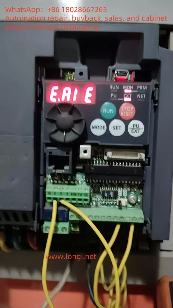
According to the Mitsubishi E700 Inverter Manual (hereinafter referred to as the manual), the E.AIE fault code indicates an abnormality in the analog input. This fault is typically related to the analog input signals (e.g., 0-10V voltage or 4-20mA current) received through terminals (such as terminals 2 or 4), which are used to set motor operating frequency or other control parameters. When the inverter detects that these signals are out of range, missing, or unstable, it triggers the E.AIE protection function, halting output and displaying the fault code on the operation panel.

Possible Triggering Conditions

  1. Signal Out of Range: Input signal exceeds the inverter’s supported range (e.g., voltage > 10V or current > 20mA).
  2. Signal Transmission Issues: Wiring problems or electromagnetic interference causing signal interruption or distortion.
  3. External Device Failure: Malfunction of devices providing the signal (e.g., potentiometers, sensors, or PLCs).
  4. Parameter Setting Errors: Incorrect settings for parameters related to analog input, such as PR.73 and PR.267.
  5. Internal Inverter Issues: Damage to the analog input circuit.

Understanding the meaning of E.AIE allows for a multi-angle analysis of its causes and the development of troubleshooting strategies.

3. Possible Causes of the E.AIE Fault

The E.AIE fault may stem from external factors or issues within the device itself. The following is a detailed breakdown of potential causes:

3.1 Abnormal Analog Input Signal

The analog input signal is typically provided by an external device to control frequency or parameters. The manual (PAGE 71) notes that the E700 series supports 0-5V, 0-10V voltage inputs, and 4-20mA current inputs. If the signal exceeds these ranges, the inverter triggers protection.

  • Possible Issues:
    • Abnormal output from an external device (e.g., voltage exceeding 10V).
    • Unstable or missing signal.
  • Example: A damaged potentiometer causing voltage fluctuations, or a PLC output module failing, resulting in current exceeding 20mA.

3.2 Wiring Issues

Wiring problems are a common cause of analog input abnormalities. The manual (PAGE 19 and PAGE 23) provides detailed wiring requirements for control circuit terminals.

  • Possible Issues:
    • Loose or Disconnected Wiring: Poor contact at terminals 2 (voltage input), 4 (current/voltage input), or 5 (common terminal).
    • Wiring Errors: Voltage signal mistakenly connected to a current terminal, or the common terminal not properly connected.
    • Electromagnetic Interference: Unshielded signal lines or proximity to power lines causing signal distortion.
  • Example: Signal lines not using shielded cables, affected by electromagnetic interference from nearby motor operation.

3.3 External Device or Sensor Failure

Analog signals are often sourced from external devices such as potentiometers, sensors, or PLCs. If these devices fail, it can lead to signal abnormalities.

  • Possible Issues:
    • Aged potentiometer causing unstable voltage output.
    • Damaged sensor interrupting the 4-20mA current signal.
    • Abnormal power supply to external devices affecting signal output.
  • Example: A 4-20mA pressure sensor outputting abnormal current due to an internal short circuit.

3.4 Parameter Setting Errors

Inverter parameter settings directly affect analog input recognition. The manual (PAGE 49 and PAGE 71) highlights key parameters:

  • PR.73 (Analog Input Selection): Defines the input type for terminal 2 (e.g., 0-10V or 4-20mA).
  • PR.267 (Terminal 4 Input Selection): Defines the input type for terminal 4, supporting 0-5V, 0-10V, or 4-20mA.
  • PR.125/PR.126 (Frequency Setting Gain): Calibrates the relationship between analog signals and frequency.
  • Possible Issues: Mismatched settings for PR.73 or PR.267 with the actual signal type, preventing correct signal recognition.
  • Example: PR.267 set to “0” (4-20mA) while the actual input is a 0-10V signal, leading to a read error.

3.5 Internal Inverter Circuit Failure

If external signals and wiring are normal but the fault persists, it may indicate a hardware issue.

  • Possible Issues:
    • Damage to the analog input circuit (e.g., A/D conversion module).
    • Aging or moisture-related degradation of internal circuits.
  • Example: Long-term operation in a humid environment causing circuit board corrosion.
E.AI E

4. Role of PR.267 in the E.AIE Fault

PR.267 is a critical parameter related to analog input, specifically used to set the input type for terminal 4. According to the manual (PAGE 71), PR.267 options include:

  • 0: 4-20mA current input.
  • 1: 0-5V voltage input.
  • 2: 0-10V voltage input.

The purpose of PR.267 is to inform the inverter how to interpret the analog signal received via terminal 4. For instance, if PR.267 is set to “0,” the inverter expects a 4-20mA current signal; if set to “2,” it expects a 0-10V voltage signal.

Relationship Between PR.267 and E.AIE Fault

When the PR.267 setting does not match the actual input signal type, the inverter may fail to recognize or process the signal correctly, triggering an E.AIE fault.

  • Mismatch Example: If PR.267 is set to “0” (current input) but the input is a voltage signal, the inverter misinterprets the data, leading to an E.AIE error.
  • Signal Out of Expected Range: Even with the correct signal type, if the PR.267 setting causes the inverter to expect a range that differs from the actual input (e.g., voltage input but exceeding 10V), a fault may occur.

Thus, checking the PR.267 setting is essential during E.AIE fault troubleshooting.

5. Steps to Resolve the E.AIE Fault

Based on the above causes, the following are systematic troubleshooting and resolution steps:

5.1 Check the Analog Input Signal

  • Action:
    • Use a multimeter to measure the signal between terminals 2 (voltage input) or 4 (current/voltage input) and terminal 5.
    • Verify the signal is within the normal range (0-5V, 0-10V, or 4-20mA).
  • Solution:
    • If the signal exceeds the range, adjust the external device output.
    • If the signal is missing, check the external device’s operation.

5.2 Inspect Wiring and Shielding

  • Action:
    • Check the integrity of terminals 2, 4, and 5 wiring, referring to the manual (PAGE 15) for the wiring diagram.
    • Ensure signal lines use shielded cables with the shield grounded (PAGE 33).
  • Solution:
    • Tighten loose terminals or replace damaged wiring.
    • Install shielded cables and keep them away from power lines to reduce interference.

5.3 Test External Devices

  • Action:
    • Disconnect the external device and use a signal generator to input a standard signal, observing if the fault disappears.
  • Solution:
    • If the fault resolves with a direct input, inspect and replace the faulty external device.

5.4 Check Parameter Settings (Focus on PR.267)

  • Action:
    • Enter parameter mode to verify PR.73 (terminal 2) and PR.267 (terminal 4) match the input signal types.
    • Specific steps:
      • Check the current value of PR.267.
      • Confirm the actual signal type at terminal 4 (voltage or current).
      • Adjust PR.267 to the matching value (e.g., “2” for 0-10V).
    • Verify PR.125 and PR.126 are correctly calibrated (PAGE 70).
  • Solution:
    • Adjust PR.73 and PR.267 to the correct values.
    • If unsure, reset parameters to factory settings (PAGE 42) and reconfigure.

5.5 Inspect Inverter Hardware

  • Action:
    • Check terminals for signs of burning or damage.
    • If possible, replace the control board for testing.
  • Solution:
    • If hardware failure is confirmed, contact Mitsubishi service or a professional technician (PAGE 113).

5.6 Reset and Test

  • Action:
    • Press the “STOP/RESET” key to reset the fault (PAGE 95).
    • Restart the inverter and conduct a trial run.
  • Solution:
    • If the fault persists, repeat the steps or seek technical support.

6. Preventive Measures

To reduce the occurrence of E.AIE faults, consider the following measures:

  1. Regular Wiring Checks: Inspect terminal integrity and signal line condition monthly.
  2. Use Quality Equipment: Select external devices compatible with the inverter.
  3. Optimize Installation Environment: Follow manual guidelines (PAGE 14) to avoid harsh conditions.
  4. Parameter Backup and Verification: Back up parameters after initial setup and periodically check PR.267 and other key settings.
  5. Regular Maintenance: Clean the inverter annually and inspect internal circuits as recommended (PAGE 113).

7. Case Study

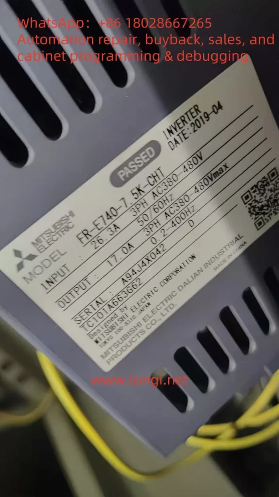
Consider a FR-E740-7.5K-CHT inverter displaying an E.AIE fault:

  • Troubleshooting: Measurement shows a 0-10V voltage input at terminal 4, but PR.267 is set to “0” (4-20mA).
  • Root Cause: PR.267 mismatch with the actual signal type.
  • Solution: Adjust PR.267 to “2” (0-10V), reset the inverter, and the fault is cleared.
  • Prevention: Record PR.267 settings and regularly inspect external devices.

8. Conclusion

The E.AIE fault in Mitsubishi E700 (E740) inverters is typically caused by abnormal analog input signals, wiring issues, external device failures, parameter setting errors (especially PR.267), or internal hardware damage. By inspecting signals, wiring, devices, parameters, and hardware, users can effectively resolve the issue. Notably, correctly setting PR.267 is crucial to avoiding E.AIE faults. Preventive measures, such as regular parameter checks and backups, enhance equipment reliability. If troubleshooting proves challenging, contacting Mitsubishi technical support is recommended to ensure production efficiency and equipment safety.

    Posted on

    Investigation into Configuration Error Issues with Siemens TIA Portal V20 S7-1500 Station_1

    1. Default Generation of Station_1 and Compilation Check Behavior

    In TIA Portal V20, when a new project is created and any S7-1500 CPU (e.g., 1517F-3 PN/DP) is added, a hardware station named “S7-1500/ET200MP station_1” (Station_1) appears in the project tree. This is a default behavior of the TIA Portal system: Whenever a PLC device is added, a station is created for hardware configuration, and automatic consistency/integrity checks are performed. Compared to the earlier STEP7 V5.x software, TIA Portal implements stricter compilation validation for hardware configurations. Even if only the default CPU itself is present without any added expansion modules, TIA Portal includes Station_1 in the compilation check scope to ensure the completeness and correctness of the hardware configuration. This is reflected in the official support documentation: Issues with incomplete station checks in older software versions have been improved in TIA to perform default integrity validations. Therefore, the automatic generation of Station_1 after adding a CPU to each new project and its verification during hardware compilation are normal system behaviors, not faults.

    S7-1500/ET200MP station_1

    2. Reasons for Integrity Errors Despite No Added Modules

    Even when no expansion modules are added and only the CPU itself remains, hardware compilation still reports a configuration error for Station_1. The main reason lies in TIA Portal’s integrity and consistency checks on hardware stations, which encompass two aspects: hardware component integrity and security/access configuration integrity.

    Firstly, from a hardware perspective, TIA checks whether the station lacks necessary modules or terminals. For example, in distributed I/O stations (such as ET200SP/ET200MP interface modules), if there is no at least one signal module or if the end “server module” (used for termination/power supply) is not inserted, compilation errors indicating incomplete configuration (e.g., “missing server module”) will be reported. This check mechanism aims to prevent empty or incorrect station configurations. For instance, some materials state: “The server module must be configured; otherwise, compilation will report an error indicating the absence of the server module.” Therefore, even if users do not manually add modules, the system performs integrity validation on Station_1 and reports errors when the default station does not meet the expected complete configuration.

    Secondly, from a security configuration perspective, TIA Portal V20 introduces a new feature of local user management and access control (UMAC) to manage CPU access permissions. If access control is enabled (enabled by default in V19 and later versions), the integrity of the CPU’s security configuration is checked even without additional modules. This means that if essential users/roles are not configured, compilation errors will also be reported (see Section 4 for details). In summary, TIA Portal still performs station integrity checks even when no modules are added because the system assumes that even with only the CPU, minimum configuration requirements in terms of both hardware and security must be met; otherwise, a “configuration error” is indicated.

    3. Default Requirements for Rail_0 Regarding Configuration Integrity

    “Rail_0” under “S7-1500/ET200MP station_1” represents the rack/rail where the CPU is located. By default, this rail station is set to require configuration integrity, meaning basic configuration completeness conditions must be satisfied.

    • Module Configuration Integrity: For modular rail systems like ET200MP/ET200SP, TIA Portal requires that each station must be correctly configured with necessary modules and end pieces. For example, in an ET200SP station, the first slot must have a module, and a server module must be inserted at the end to close the backplane bus; otherwise, compilation errors will be reported. Although the S7-1500 main station integrates the backplane and does not require a separate server module like remote stations, Rail_0 still assumes by default that “unreasonable empty configurations” are not allowed. If a user adds a remote ET200MP station under Station_1 but does not place any modules, the system will also report errors during compilation indicating missing modules or accessories, thereby forcing the user to complete the hardware configuration.
    • Configuration Integrity Check Options: In TIA hardware configuration, there is no explicit requirement to fill in parameters such as “total number of slots” (the system automatically determines this based on the configured modules). However, the station itself has an implicit integrity validation mechanism that does not allow the absence of key components. This includes situations such as module absence mentioned above and the absence of security-related configurations in the case of safety CPUs. Rail_0 enables these integrity check rules by default, so even with only the CPU, it must pass security configuration checks (see the following section for details).

    It should be noted that a power module is not a mandatory configuration item for the S7-1500 main station. The S7-1500 CPU comes with basic power supply and does not require a separate power module like the S7-300. Therefore, Rail_0 does not require a power module to be inserted for successful compilation (unless additional power supply expansion is actually needed). Rail_0 is more concerned with the logical integrity of the station: for remote stations, whether there are I/O modules and terminals; for local main stations, whether access control configurations are met, etc. Therefore, “Rail_0 requires configuration integrity” is manifested in the fact that errors are triggered by the absence of necessary modules or necessary configurations. This is a system default setting used to ensure that the hardware configuration is consistent with the actual hardware installation.

    4. F-CPU Security Functions and User Role Requirements

    When using an S7-1500 F-CPU with fail-safe functions (such as 1517F-3 PN/DP), compilation errors are often related to security access permission configurations. Since TIA Portal V19, a new mechanism of local user and role management (access control) has been introduced and is enabled by default for all newly added CPUs. Once enabled, the system requires that at least one user be granted full access permissions to the CPU; otherwise, hardware configuration cannot pass compilation. The official documentation clearly states: “At least one user must have full access permissions to the CPU; otherwise, the configuration cannot be compiled.” For fail-safe CPUs (F-CPUs), the requirements are further enhanced—this user must also have “full access including fail-safe” permissions to perform download and operation operations on the F-CPU. In other words, if an F-series CPU is used but no user is granted fail-safe access permissions in user management, compilation/download operations will terminate with error reports. This is usually manifested as error messages in the compilation information similar to “at least one user must have full access permissions including fail-safe.”

    The reason for this requirement is that F-CPUs involve security functions. To prevent unauthorized changes, TIA Portal includes fail-safe permissions as part of the configuration integrity check. When access control is activated, the old method of protecting access levels through simple passwords is replaced by user/role permission management. Therefore, for CPUs like the 1517F, user role configurations must be in place (e.g., creating an “Admin” user and granting it the “full access (including F access)” role) before hardware can be successfully compiled and loaded. If the user does not configure any local user roles (the TIA Portal starts with an empty configuration for new projects), the compiler considers the security configuration incomplete and reports errors indicating configuration errors.

    In short, security functions make F-CPUs subject to an additional check compared to ordinary CPUs: whether a user with sufficient permissions exists. If not, Station_1 will fail during compilation. This is the root cause of the problems encountered by many users and needs to be resolved by appropriately configuring user roles.

    CPU 1518TF-4 PN/DP

    5. Impact of Project Templates or System Default Settings

    After investigation, it has been found that TIA Portal V20 does not have a special “project template” that would generate an ET200MP station for no reason and cause errors; the problems are more likely due to the combined effects of system default settings and the selected CPU type:

    • Local User Access Control Enabled by Default: As mentioned earlier, since V19, access control functions for CPUs have been enabled by default in new TIA projects. This is not a template specifically chosen by the user but a system-wide default behavior. Therefore, after adding a CPU to each new project, the “enable access control” option is already checked in its properties, forcing the user management mechanism to take effect. If the user is unaware of this change and directly compiles without configuring any users, errors will occur.
    • Default Requirements for Fail-Safe CPUs: When a user selects an F-series CPU, it is equivalent to enabling fail-safe support by default. This is not forced by a template but is triggered by the hardware’s own characteristics, which lead TIA Portal to require security configurations (i.e., requiring F-CPU to configure F user permissions). Therefore, it is not a template that causes errors in Station_1 but rather the incomplete default security settings that prevent successful compilation.
    • Automatic Generation of Station_1: When creating a new project in TIA Portal using a wizard, a PLC device (Station_1) may sometimes be automatically added. However, whether added manually or generated through default configuration, this station itself is not the source of errors; the errors lie in the incomplete configuration within the station. In other words, TIA does not generate an invalid station for no reason; instead, it generates a station that requires further configuration. If no modifications are made and compilation is performed directly, error messages will be seen. All of this is attributable to the system default configuration strategy of TIA Portal V20, not to the user selecting an incorrect project template.

    In summary, the system default settings of TIA Portal V20 (enabling access control, hardware integrity checks, etc.) are the main reasons for compilation errors in Station_1. There is currently no evidence indicating the existence of an official project template that specifically “forces the generation” of this station and causes errors; rather, it is the general default mechanisms that are at play.

    6. Solution Steps to Eliminate Such Hardware Compilation Errors

    For Station_1 hardware configuration errors that occur when no additional modules are added, users have several feasible countermeasures to eliminate the errors:

    • Configure Local Users and Role Permissions: This is the officially recommended method. If access control functions continue to be used, add at least one user in the project’s “Users and Roles” editor and create/assign a role with full access permissions (for F-CPUs, assign the role of “full access (including fail-safe)”). For example, create a user named “Admin” and grant it full control permissions over the CPU. In this way, during hardware configuration compilation, TIA Portal will detect that the necessary user roles exist, and the errors will disappear.
    • Disable Access Control: If the project does not require enabling CPU user access management, this function can be turned off. Select the CPU and, in the property window’s “Protection & Security > Access control” tab, uncheck “enable access control.” After disabling it, TIA will revert to traditional simple access level protection (or no protection) and will no longer require configuring users/roles. It should be noted that after disabling access control, ensure that no CPU services requiring user authentication (such as Web servers, OPC UA servers, etc.) are enabled, as these services will also require at least one user to have corresponding access permissions if enabled. In general, disabling access control can immediately eliminate compilation errors caused by the absence of user roles.
    • Complete Hardware Station Configuration: If the error is not due to security settings but rather due to incomplete configuration of the station itself (e.g., an additionally added ET200MP remote station has no modules), the configuration should be completed according to hardware requirements. For example, add at least one I/O module to the remote station and insert a server module (e.g., the server end cap module for ET200SP systems) in the last slot, or delete unnecessary empty stations. Ensure that each hardware station has a reasonable composition: for the main station CPU, usually the CPU itself is sufficient; for remote stations, at least an interface module + I/O module + server end cap are required.
    • Replace with a Non-Safety CPU (Optional): If the project does not actually require safety functions and the error is only caused by selecting an F-CPU, consider replacing it with a corresponding standard CPU (e.g., replacing the 1517F with the 1517 standard model). Standard CPUs only require a “full access” user when access control is enabled and do not involve “fail-safe” permissions, making the configuration slightly simpler. However, this measure should only be adopted when it is certain that safety functions are not needed; usually, the problem can be solved by configuring user roles as mentioned above without replacing the CPU hardware.
    • Check and Delete Redundant Stations: Confirm whether there are duplicate or unused stations in the project unintentionally. For example, some users have encountered conflicts between two stations with the same name when uploading/merging projects. If there is an unfinished Station_1 in the project in addition to the main CPU station, it can be deleted. Usually, new projects do not generate extra stations for no reason, but this may happen when importing other configurations or templates. Therefore, keeping the hardware station list in the project clean and removing any unnecessary stations helps avoid compilation errors.

    After following the above steps to handle the issue, recompile the hardware configuration, and the errors should be eliminated. For example, many users report that simply disabling the CPU’s access control or correctly creating user roles can resolve the “S7-1500/ET200MP Station_1” configuration error. In conclusion, the key to solving the problem lies in meeting TIA Portal’s requirements for station integrity: either complete the security settings or adjust the hardware configuration so that Station_1 is no longer considered an incomplete configuration. After making these adjustments, the hardware compilation in TIA Portal V20 will pass successfully without error messages.

    Posted on

    Understanding and Resolving ER055 Hardware Overvoltage Fault in Hilectro HI282 Servo Systems

    Introduction

    In the realm of industrial automation, servo systems are pivotal for achieving precise motion control, finding widespread use in CNC machines, robotics, packaging lines, and more. However, as complex electronic devices, servo systems can encounter faults that disrupt production. The ER055 hardware overvoltage fault (Hardware Overvoltage Fault) in the Hilectro HI282 series servo system is a common issue that can severely impact equipment operation. This article delves into the meaning of the ER055 fault, its potential causes, resolution methods, and preventive measures, empowering users to diagnose and address the problem efficiently while ensuring system stability.

    ER055

    Meaning of the ER055 Fault

    The ER055 fault code in the Hilectro HI282 series servo system signifies a “hardware overvoltage” condition. This indicates that the internal voltage within the servo driver has exceeded its safe operating range, potentially triggering protective mechanisms that halt operation. According to the HI2xx series servo manual (Version 5.51), fault codes are typically displayed as “ErOSX,” where X denotes a specific fault number. For instance, “ErOS5” corresponds to fault number 53, indicating a system error. ER055 likely represents fault number 55, specifically a hardware overvoltage error, often linked to power supply, regenerative energy, or hardware issues requiring immediate attention.

    Common Causes of ER055 Hardware Overvoltage Fault

    Several factors may contribute to a hardware overvoltage fault, including:

    1. Excessive Power Supply Voltage
      If the voltage supplied to the servo driver exceeds its rated value, it can trigger overvoltage protection. For example, the HI282 series driver typically operates within a specified voltage range (details in the manual), and exceeding this range can lead to an ER055 fault.
    2. Excessive Regenerative Energy
      During rapid motor deceleration, the servo motor generates regenerative energy (converting kinetic energy into electrical energy fed back to the driver). If the driver’s regenerative resistor lacks sufficient capacity or is faulty, this energy can cause internal voltage spikes, triggering the fault.
    3. Internal Component Failure
      Faulty voltage detection circuits, power modules, or capacitors within the driver can lead to inaccurate voltage monitoring or actual voltage anomalies. For instance, aged capacitors or damaged transistors might be culprits.
    4. Wiring and Grounding Issues
      Improper wiring, loose connections, or inadequate grounding can result in voltage fluctuations or interference, activating overvoltage protection. Examples include loose power lines or improper grounding setups.

    The following table summarizes potential causes and their characteristics:

    CauseCharacteristicsPotential Impact
    Excessive Power VoltageInput voltage exceeds rated rangeDriver halts, displays ER055
    Excessive Regenerative EnergyVoltage rise during rapid decelerationOvervoltage protection triggered
    Internal Component FailureAbnormal voltage detection or hardware damageFrequent faults or unresolvable issues
    Wiring/Grounding IssuesVoltage spikes or interferenceUnstable operation, intermittent faults
    HI282

    Steps to Resolve ER055 Hardware Overvoltage Fault

    Resolving an ER055 fault requires a systematic troubleshooting approach. The following steps are recommended:

    1. Check Power Supply Voltage
      • Use a multimeter to measure the input voltage to the servo driver, ensuring it aligns with the rated range specified in the HI282 manual.
      • If the voltage is too high, inspect the power source (e.g., transformer or regulator) and adjust it accordingly.
      • Ensure power stability to avoid fluctuations or spikes.
    2. Inspect Regenerative Resistor
      • Confirm the presence and functionality of the regenerative resistor.
      • Check for signs of burnout, open circuits, or shorts.
      • Replace with a resistor of adequate capacity if it’s insufficient (refer to manual recommendations).
    3. Inspect Internal Components
      • Look for abnormal signs in the driver, such as overheating, unusual noises, or a burnt smell, which may indicate component failure.
      • Note: Non-professionals should not disassemble the driver; contact a Hilectro authorized service center for repairs.
    4. Examine Wiring and Grounding
      • Ensure all power, signal, and ground connections are secure and correctly configured, with no loose or broken wires.
      • Verify grounding meets manufacturer standards, as proper grounding reduces interference and voltage spikes.
      • Use an oscilloscope to check for voltage surges or electromagnetic interference.
    5. Reset the Driver
      • Attempt a power cycle by disconnecting the power, waiting a few minutes, then restarting to see if the fault clears.
      • If the driver has a “STOP” button, press it to attempt clearing the error state (ERR status), returning the driver to READY mode.
    6. Review Parameter Settings
      • Access the driver’s parameter settings to check configurations related to voltage or regenerative control.
      • If misconfigured, restore factory settings or adjust parameters per the manual.
    7. Consult the Manual or Contact Technical Support
      • Refer to the HI282 series user manual for the specific definition of ER055 and recommended troubleshooting steps.
      • If unavailable or unresolved, contact Hilectro technical support with details of the fault code and operating conditions.
    8. Consider Driver Replacement
      • If the above steps fail and the driver is out of warranty or repair costs are high, consider replacing it.
      • Ensure the new driver’s model and specifications are compatible with the system.

    The following table outlines the resolution steps and precautions:

    StepActionPrecautions
    Check Power VoltageMeasure input voltageStay within rated range
    Inspect Regenerative ResistorCheck status and capacityAvoid using damaged or mismatched resistors
    Inspect Internal ComponentsObserve for anomaliesRequire professional handling
    Check Wiring/GroundingEnsure secure connections, proper groundingCheck for voltage spikes or interference
    Reset DriverPower cycle or press STOP buttonRecord fault status before/after
    Review ParametersAdjust or reset settingsRefer to manual to avoid errors
    Contact SupportProvide fault detailsPrepare model and logs
    Replace DriverSelect compatible modelEnsure system compatibility

    Preventive Measures for ER055 Faults

    To prevent recurrence of ER055 faults, consider the following measures:

    1. Regular Maintenance
      • Periodically inspect the driver’s operating condition, including temperature, noise, and vibration.
      • Clean cooling fans and heat sinks to ensure effective heat dissipation.
      • Check the aging of capacitors, resistors, and other wear-prone components, replacing them as needed.
    2. Stable Power Supply
      • Use reliable power equipment to maintain input voltage within the driver’s rated range.
      • Install voltage regulators or UPS (uninterruptible power supply) to mitigate voltage fluctuations.
    3. Proper Acceleration/Deceleration Control
      • Set reasonable acceleration and deceleration times in the servo system’s control parameters to minimize regenerative energy.
      • Ensure the regenerative resistor’s capacity is sufficient for rapid deceleration scenarios.
    4. Correct Wiring and Grounding
      • Follow the manual’s guidelines for wiring and grounding to prevent faults caused by improper connections.
      • Use shielded cables to reduce electromagnetic interference.
    5. Train Operators
      • Ensure operators are familiar with the servo system’s operation and maintenance, enabling them to identify and report issues promptly.
      • Provide training on fault troubleshooting and prevention to enhance team capability.
    hi282

    Conclusion

    The ER055 hardware overvoltage fault is a common issue in the Hilectro HI282 series servo systems, typically caused by excessive power voltage, regenerative energy overload, internal component failure, or wiring problems. Through systematic troubleshooting—such as checking the power supply, regenerative resistor, wiring, and parameter settings—users can effectively resolve this fault. Additionally, adopting preventive measures like regular maintenance, stable power, and proper control settings can significantly reduce fault occurrences, ensuring long-term system reliability. If the problem persists, contacting Hilectro technical support or a professional repair service is advised for detailed guidance or repairs.

    Posted on

    Simple Control Guide for Driving General Asynchronous Motors with V/F Mode on Vacon NXP Series Inverters

    According to the “Vacon NXP Programming Manual” (APFIFF08 ADVANCE), to configure the Vacon NXP inverter for use with a general asynchronous motor and employ a simple V/F (Voltage/Frequency) control mode, key parameters and steps must be set. These parameters primarily focus on motor control mode, basic motor parameters, and V/F control settings. Below is a detailed guide:

    application manabe winch

    1. Set Motor Control Mode to V/F Control

    According to Page 143 of the manual, set the motor control mode to V/F control.

    • Parameter: P2.8.1 Motor Control Mode (Motor Ctrl Mode, ID600)
    • Path: Control Panel Menu M2 -> G2.8.1
    • Setting Value: 0 (“Frequency Control”, indicating V/F control mode)
    • Explanation: Selecting V/F control mode allows the inverter to control the motor through a fixed ratio of voltage to frequency, without using closed-loop control (such as speed or torque control).

    2. Set Basic Motor Parameters

    To ensure proper motor operation in V/F control mode, correctly set the motor’s rated parameters, which are typically found on the motor nameplate. The following parameters are described on Pages 63-65 of the manual:

    • P2.1.1 Motor Rated Voltage (Nominal Voltage, ID110)
      • Path: Control Panel Menu M2 -> G2.1
      • Setting Value: According to the rated voltage on the motor nameplate (e.g., 380V, 400V, etc.)
      • Explanation: Set the motor’s rated voltage to ensure the inverter outputs the correct voltage.
    • P2.1.2 Motor Rated Frequency (Nominal Frequency, ID111)
      • Path: Control Panel Menu M2 -> G2.1
      • Setting Value: According to the rated frequency on the motor nameplate (e.g., 50Hz or 60Hz)
      • Explanation: Set the motor’s rated operating frequency.
    • P2.1.3 Motor Rated Speed (Nominal Speed, ID112)
      • Path: Control Panel Menu M2 -> G2.1
      • Setting Value: According to the rated speed on the motor nameplate (e.g., 1470 rpm, etc.)
      • Explanation: Used to calculate the motor’s pole pairs and slip.
    • P2.1.4 Motor Rated Current (Nominal Current, ID113)
      • Path: Control Panel Menu M2 -> G2.1
      • Setting Value: According to the rated current on the motor nameplate (e.g., 10A, 20A, etc.)
      • Explanation: Ensure the inverter does not operate overloaded.
    • P2.1.5 Motor Power Factor (Cos Phi, ID120)
      • Path: Control Panel Menu M2 -> G2.1
      • Setting Value: According to the power factor on the motor nameplate (e.g., 0.85)
      • Explanation: Used to optimize motor efficiency calculations.
    • P2.1.11 Magnetizing Current (Magnetizing Current, ID612) (Optional)
      • Path: Control Panel Menu M2 -> G2.1
      • Setting Value: According to the magnetizing current on the motor nameplate (if provided), or automatically identified through “ID No Run” (see Page 158).
      • Explanation: If unsure, run “ID No Run” (without rotating the motor) to automatically identify the magnetizing current.

    3. Set V/F Curve Parameters

    The V/F control mode requires defining the relationship curve between voltage and frequency to ensure the motor receives the appropriate voltage at different frequencies. These parameters are described in detail on Page 144 of the manual:

    • P2.8.1.1 V/F Curve Type (V/f Curve, ID108)
      • Path: Control Panel Menu M2 -> G2.8.1
      • Setting Value: 0 (“Linear”, linear V/F curve, suitable for general asynchronous motors)
      • Explanation: The linear V/F curve is the simplest control method, suitable for most general asynchronous motor applications.
    • P2.8.1.2 Field Weakening Point (Field Weakening Point, ID602)
      • Path: Control Panel Menu M2 -> G2.8.1
      • Setting Value: Typically set to the motor’s rated frequency (e.g., 50Hz)
      • Explanation: The field weakening point defines the frequency at which the motor enters the field weakening region, usually consistent with the rated frequency.
    • P2.8.1.3 Voltage at Field Weakening Point (Voltage at Field Weakening Point, ID603)
      • Path: Control Panel Menu M2 -> G2.8.1
      • Setting Value: Typically set to 100% (i.e., the motor’s rated voltage)
      • Explanation: Ensure the motor receives the rated voltage at the field weakening point.
    • P2.8.1.4 V/F Midpoint Frequency (V/f Midpoint Frequency, ID604) (Optional)
      • Path: Control Panel Menu M2 -> G2.8.1
      • Setting Value: Typically set to half of the rated frequency (e.g., 25Hz)
      • Explanation: Used to optimize the V/F curve during low-frequency operation, usually not requiring adjustment.
    • P2.8.1.5 V/F Midpoint Voltage (V/f Midpoint Voltage, ID605) (Optional)
      • Path: Control Panel Menu M2 -> G2.8.1
      • Setting Value: Typically set to the percentage of voltage at the midpoint frequency (e.g., 50%)
      • Explanation: Used with the midpoint frequency to define a non-linear V/F curve; the default value can be maintained for general applications.

    4. Set Frequency Range

    According to Pages 10 and 130 of the manual, set the range of the output frequency:

    • P2.1.6 Minimum Frequency (Minimum Frequency, ID101)
      • Path: Control Panel Menu M2 -> G2.1
      • Setting Value: Typically set to 0 Hz or the lowest frequency required by the application (e.g., 5 Hz)
      • Explanation: Defines the lowest frequency output by the inverter.
    • P2.1.7 Maximum Frequency (Maximum Frequency, ID102)
      • Path: Control Panel Menu M2 -> G2.1
      • Setting Value: Set according to application requirements (e.g., 50Hz, 60Hz, or higher, up to a maximum of 599Hz)
      • Explanation: Defines the highest frequency output by the inverter, ensuring it does not exceed the motor’s design range.
    • P2.6.4.1 Negative Frequency Limit (Negative Frequency Limit, ID1286) (Optional)
      • Path: Control Panel Menu M2 -> G2.6.4
      • Setting Value: If reverse operation is not required, set to 0 Hz
      • Explanation: Limits the frequency at which the motor can operate in reverse; typically not required for general asynchronous motor applications.
    Electrical Cabinet Diagram for VACON NXP Application on Ships

    5. Set Acceleration and Deceleration Times

    Acceleration and deceleration times affect the smoothness of motor startup and shutdown. These parameters are described on Pages 90-91 of the manual:

    • P2.3.3 Acceleration Time 1 (Acceleration Time 1, ID103)
      • Path: Control Panel Menu M2 -> G2.3
      • Setting Value: Set according to application requirements (e.g., 5 seconds, 10 seconds, etc.)
      • Explanation: Defines the time required to accelerate from 0 Hz to the maximum frequency.
    • P2.3.4 Deceleration Time 1 (Deceleration Time 1, ID104)
      • Path: Control Panel Menu M2 -> G2.3
      • Setting Value: Set according to application requirements (e.g., 5 seconds, 10 seconds, etc.)
      • Explanation: Defines the time required to decelerate from the maximum frequency to 0 Hz.

    6. Input Signal Settings (Startup/Stop and Frequency Reference)

    V/F control typically requires defining the sources of startup/stop signals and frequency reference signals. The following parameters are described on Pages 94-97 of the manual:

    • P2.4.1.1 Startup/Stop Logic (Start/Stop Logic, ID300)
      • Path: Control Panel Menu M2 -> G2.4.1
      • Setting Value: 0 (“Start/Stop”, simple two-wire control, closed to start, open to stop)
      • Explanation: Select simple startup/stop logic suitable for general applications.
    • P2.2.2 I/O Frequency Reference Selection 1 (I/O Reference Selection 1, ID117)
      • Path: Control Panel Menu M2 -> G2.2
      • Setting Value: 0 (“Analogue Input 1”, analog input 1) or 3 (“Keypad”, control panel)
      • Explanation: Select the source of the frequency reference, such as through an external analog signal (0-10V or 4-20mA) or the control panel.
    • P2.4.3.1 Analog Input 1 Signal Selection (AI1 Signal Selection, ID377)
      • Path: Control Panel Menu M2 -> G2.4.3
      • Setting Value: Select according to actual wiring (e.g., “AI1” for analog input 1)
      • Explanation: If using an external analog signal to control the frequency, configure the correct input channel.

    7. Run Identification (Optional)

    To optimize V/F control performance, it is recommended to run a motor parameter identification once. According to Page 158 of the manual:

    • P2.8.8.1 Identification (Identification, ID631)
      • Path: Control Panel Menu M2 -> G2.8.8
      • Setting Value: 1 (“ID No Run”, identification without rotating the motor)
      • Explanation: Run “ID No Run” to automatically identify motor parameters (such as magnetizing current) without rotating the motor, suitable for initial setup.

    8. Inspection and Verification

    • Check Wiring: Ensure the motor is wired correctly and control signals (such as startup/stop and frequency reference) are connected to the correct terminals (refer to the Control I/O section on Page 11 of the manual).
    • Monitor Values: Check output frequency (V1.1, ID1), motor current (V1.23.1, ID1113), etc., in the control panel menu M1 to ensure normal operation (refer to Pages 16-19 of the manual).
    • Fault Checking: If a fault occurs (such as overcurrent F1, undervoltage F9, etc.), refer to the fault code table on Pages 210-221 of the manual for troubleshooting.

    9. Summary

    Below is the minimum parameter set for configuring the V/F control mode for a general asynchronous motor:

    • P2.8.1 Motor Control Mode: 0 (Frequency Control)
    • P2.1.1 Motor Rated Voltage: Set according to the nameplate (e.g., 380V)
    • P2.1.2 Motor Rated Frequency: Set according to the nameplate (e.g., 50Hz)
    • P2.1.3 Motor Rated Speed: Set according to the nameplate (e.g., 1470 rpm)
    • P2.1.4 Motor Rated Current: Set according to the nameplate (e.g., 10A)
    • P2.1.5 Motor Power Factor: Set according to the nameplate (e.g., 0.85)
    • P2.8.1.1 V/F Curve Type: 0 (Linear)
    • P2.8.1.2 Field Weakening Point: Rated frequency (e.g., 50Hz)
    • P2.8.1.3 Voltage at Field Weakening Point: 100% (rated voltage)
    • P2.1.6 Minimum Frequency: 0 Hz or application requirements
    • P2.1.7 Maximum Frequency: 50Hz or application requirements
    • P2.3.3 Acceleration Time 1: e.g., 5 seconds
    • P2.3.4 Deceleration Time 1: e.g., 5 seconds
    • P2.4.1.1 Startup/Stop Logic: 0 (Start/Stop)
    • P2.2.2 I/O Frequency Reference Selection 1: 0 (Analogue Input 1) or 3 (Keypad)

    It is recommended to run “ID No Run” identification (P2.8.8.1 = 1) after setting up to optimize motor parameters. If further adjustments are needed (such as low-speed torque compensation or prohibited frequencies), refer to Page 85 (Prohibited Frequencies) or Page 144 (U/f Settings) of the manual.

    Posted on

    Solve the OCn Fault (Overcurrent During Constant Speed) of the Sanken SAMCO-VM05 Series Inverter

    Introduction

    In the field of industrial automation, Variable Frequency Drives (VFDs) are core devices for controlling the rotational speed of AC motors, widely used in scenarios such as water pumps, conveyor belts, elevators, and machine tools. The Sanken SAMCO-VM05 series inverter is renowned for its compact design, high performance, and low noise characteristics. However, during operation, inverters may encounter faults, with the OCN fault (overcurrent during constant speed) being one of the more common issues. This article will delve into the definition, possible causes, solutions, and preventive measures of the OCN fault, providing users with a clear and practical guide.

    samco-vm05

    What is an Inverter?

    An inverter is an electronic device that converts a fixed-frequency power supply into a variable-frequency power supply for precise control of the rotational speed of AC motors. By adjusting the output frequency, inverters enable smooth motor starting, energy-efficient operation, and process optimization. In industrial applications, inverters not only improve equipment efficiency but also extend motor life and reduce maintenance costs.

    The Sanken SAMCO-VM05 series inverter is a compact vector control inverter suitable for various industrial scenarios. Its main features include high performance, low noise, and ease of operation, making it particularly suitable for applications such as water pump systems, elevators, and machine tools. However, even high-quality inverters may experience faults due to various reasons, such as the OCN fault.

    Definition of the OCN Fault

    The OCN fault indicates that the Sanken SAMCO-VM05 inverter detects that the motor current exceeds its rated value during constant speed operation. This fault is typically displayed on the inverter’s control panel as “OCN” or a similar code (e.g., “αCη ※ 3”), prompting operators to take immediate action. Overcurrent can lead to damage to the inverter or motor, making timely diagnosis and resolution crucial.

    Based on manuals for similar models (e.g., SAMCO-NS series) and fault code information provided by users, the OCN fault is typically associated with the following issues:

    • Output circuit short-circuit or ground fault.
    • Abnormal internal switching elements (e.g., IGBTs).
    • Excessive or sudden load changes.
    • Improper parameter settings.
    • Motor faults.

    Possible Causes of the OCN Fault

    To effectively resolve the OCN fault, it is essential to understand its potential causes. The following are common factors that may lead to overcurrent during constant speed:

    1. Output Short-Circuit or Ground Fault

    A short-circuit or ground fault in the output circuit can cause a sudden increase in current, triggering the OCN fault. This may be caused by:

    • Cable damage, such as broken or exposed insulation.
    • Loose or poor connections.
    • Insulation failure due to moisture or contamination.

    2. Abnormal Internal Switching Elements

    Power semiconductor elements (e.g., IGBTs) inside the inverter may fail due to:

    • Aging from long-term use.
    • Element damage caused by overheating.
    • Manufacturing defects.

    3. Excessive or Fluctuating Load

    If the motor load exceeds its rated capacity or experiences sudden changes, it may cause a current surge. For example:

    • Load exceeding the design range of the motor and inverter.
    • Mechanical system (e.g., conveyor belt) experiencing jamming or sudden increases in resistance.

    4. Improper Parameter Settings

    The parameter settings of the inverter directly affect its operational performance. The following setting errors may lead to overcurrent:

    • Excessively short acceleration/deceleration times, resulting in high current demand.
    • Excessively high current limit value (e.g., Cd043).
    • Improper torque compensation settings.
    ocn

    5. Motor Faults

    Faults in the motor itself may also trigger the OCN fault, such as:

    • Winding damage or short-circuit.
    • Increased mechanical resistance due to bearing wear.
    • Ground fault caused by motor insulation aging.

    Fault Code Table

    The following table, compiled based on fault code information provided by users, lists codes related to the OCN fault and their descriptions:

    Fault CodeDescriptionCheck Points
    αCη ※ 3Overcurrent during constant speedIs there an output short-circuit or ground fault?
    αCη ※ 3Overcurrent during accelerationIs the operation involving abrupt acceleration/deceleration?
    αCη ※ 3Overcurrent during decelerationIs there an abnormality in the main switching element itself?
    αCPηShort-term overload during constant speedIs the current limit value Cd043 too high?

    Note: The OCN fault corresponds to “overcurrent during constant speed.”

    Steps to Resolve the OCN Fault

    The following are systematic steps to resolve the OCN fault, aimed at helping users quickly locate and resolve the issue:

    1. Check the Output Circuit

    Steps:

    • Inspect the cable from the inverter to the motor for signs of damage, burns, or exposure.
    • Ensure all terminal connections are secure and free from looseness.
    • Use a multimeter to check for short-circuits or ground faults in the circuit.

    Note: Before inspection, be sure to disconnect the power supply to ensure safety.

    2. Verify the Load

    Steps:

    • Confirm that the motor load is within the rated range.
    • Check for sudden load changes, such as mechanical jamming.
    • If the load is excessive, consider reducing the load or replacing the motor and inverter with higher-power units.

    Note: Load fluctuations may require adjustments to the process flow or the addition of buffer devices.

    3. Check the Motor

    Steps:

    • Visually inspect the motor for physical damage, such as a cracked casing or unusual noises.
    • Use an insulation tester to check the motor’s insulation resistance to ensure no ground faults exist.
    • If possible, test the motor with another inverter to confirm whether the fault is caused by the motor.

    Note: Motor maintenance should be performed regularly to avoid potential issues.

    4. Adjust Parameters

    Steps:

    • Enter the inverter’s parameter setting menu to check the current limit value (e.g., Cd043), acceleration/deceleration times, and torque compensation settings.
    • Adjust the parameters according to the load characteristics to ensure they match the application requirements.
    • Refer to the recommended settings in the Sanken SAMCO-VM05 manual.

    Note: Parameter adjustments should be made cautiously, and it is advisable to record the original settings for restoration if necessary.

    5. Check the Cooling System

    Steps:

    • Inspect the cooling systems of the inverter and motor to ensure that the fans and heat sinks are functioning properly.
    • Measure the ambient temperature to ensure it does not exceed the inverter’s rated operating temperature.
    • Clean dust and debris to improve ventilation.

    Note: Overheating can cause element damage and requires special attention.

    6. Reset the Inverter

    Steps:

    • Turn off the inverter’s power supply and wait a few minutes before restarting it.
    • Observe whether the fault disappears. If it does, continue monitoring the system’s operation.

    Note: If the fault recurs, further hardware inspection is required.

    7. Contact Technical Support

    Steps:

    • If the above steps fail to resolve the issue, contact Sanken technical support or a professional technician.
    • Provide the fault code, system configuration, and the steps you have already attempted to facilitate quick diagnosis.

    Note: Internal element faults may require professional repair or replacement.

    Preventive Measures

    To reduce the occurrence of the OCN fault, the following preventive measures are recommended:

    Regular Maintenance:

    • Regularly inspect the inverter, motor, and circuit, clean dust, and ensure proper ventilation.
    • Check for loose terminal connections and aging cables.

    Proper Installation:

    • Install the inverter in a dry, clean, and well-ventilated environment.
    • Use cables that meet specifications and ensure secure connections.

    Appropriate Selection:

    • Ensure that the power of the inverter and motor matches the application requirements to avoid overloading.

    Parameter Configuration:

    • Correctly set parameters according to the Sanken manual and application requirements to avoid faults caused by incorrect settings.

    Personnel Training:

    • Train operators and maintenance personnel to ensure they are familiar with the operation and fault handling procedures of the inverter.

    Conclusion

    The OCN fault (overcurrent during constant speed) of the Sanken SAMCO-VM05 series inverter may be caused by various factors, including output short-circuits, load issues, improper parameter settings, or hardware faults. Through systematic inspection and adjustment, users can effectively resolve this issue. Regular maintenance, proper installation, and appropriate parameter configuration are key to preventing faults. If the problem persists, it is advisable to contact Sanken technical support or a professional technician for in-depth diagnosis.

    By following the guidelines provided in this article, users can better understand and handle the OCN fault, ensuring the stable operation and long-term reliability of the inverter system.

    References

    • Sanken SAMCO-NS Series Manual (Reference for Similar Models)
    • Fault Code List Provided by Users (Attachment ID: 2)
    Posted on

    Comprehensive User Guide for the ParticleTrack™ G400 Laser Particle Characterization System

    The ParticleTrack G400 from Mettler‑Toledo is an advanced in situ particle analysis system based on Focused Beam Reflectance Measurement (FBRM®) technology. It enables real-time, direct measurements of particle size and count in full-concentration processes without the need for sampling or dilution. This comprehensive guide explains the working principle, installation, configuration, calibration, operation, maintenance, troubleshooting, and advanced integration options of the ParticleTrack G400 system. It is designed to support users from first-time setup to expert-level deployment in laboratory or process environments.

    ParticleTrack G400

    1. Working Principle and Key Advantages

    The ParticleTrack G400 uses a rotating 780 nm laser beam focused just beyond the sapphire window of the probe. When the beam intersects a particle or droplet, it reflects back to the detector. The duration of this reflection is converted into a “chord length”, allowing the system to calculate particle size distributions in real time.

    Key advantages include:

    • True in-situ analysis without the need for sample extraction or dilution.
    • Wide dynamic range measuring particles from 0.5 µm to 2 000 µm.
    • Real-time monitoring, with updates as frequently as every second.
    • Modular probe design, including interchangeable tips for different reactor volumes.
    • Process-resilient construction, handling temperatures from –80 °C to +90 °C and pressures up to 100 bar.

    2. System Components and Safety Considerations

    ComponentDescriptionKey Specifications
    Base UnitHouses laser, motor, signal processing hardware100–240 VAC, USB, 3.25 kg
    FBRM ProbeSensor head for immersion in process streamAvailable in 14 mm / 19 mm diameters
    Software (iC FBRM)Interface for configuration, data capture, analyticsWindows-based, OPC UA/DCS compatible

    Safety Notes:

    • The system is classified as a Class 1 laser product and is safe under normal operating conditions.
    • Only trained personnel should handle system components.
    • The internal laser module and electronics are not user-serviceable.
    • Always ensure the system is properly grounded and installed indoors.

    3. Installation and Probe Positioning

    Installation steps:

    1. Hardware setup:
      • Connect the AC power supply and USB cable to the computer.
      • Confirm the “Power” and “HW-Status” LEDs are illuminated steadily.
    2. Process positioning:
      • Install the probe in a location where flow is continuous and representative.
      • The sapphire window should face the flow direction at a 30°–60° angle, ideally 45°, to maximize measurement accuracy and reduce buildup.
    3. Optional air purge:
      • In cold or humid environments, connect clean, dry instrument air at 1 barg during start-up, then reduce to 0.15 SLPM to avoid condensation.

    4. Software Operation (iC FBRM 4.4)

    4.1 Experiment Setup

    • Open iC FBRM.
    • Select New Experiment.
    • Enter a name, define the data storage path, set the total run duration, and choose a measurement interval (e.g., 1s, 5s, 30s).

    4.2 Real-Time Monitoring

    • Color-coded status indicator:
      • Green: Running
      • Yellow: Paused
      • Red: Error
      • Blue: Stopped
    • You can annotate events (e.g., reagent addition) directly onto live trends.

    4.3 Data Review & Reporting

    • Use Trend Viewer to monitor D50, counts/sec, and chord counts over time.
    • Distribution Viewer displays real-time and historical chord length distributions.
    • Statistics Viewer shows mean, mode, and percentile summaries.
    • Export data to Word, Excel, PDF, or CSV for documentation or analysis.

    5. Calibration and Validation

    TaskFrequencyPurpose
    Calibration ValidationEvery 3–6 months or after a fallVerifies scan geometry and optical alignment
    Chord Selection ModelBefore each new experimentOptimize detection for fine/coarse particles

    Validation procedure:

    • Use the Calibration Validation Wizard in iC FBRM.
    • Mount a standard PVC reference sample in a fixed beaker stand.
    • Run validation and compare results to reference data.
    • Acceptable deviation: less than 5%; if more than 10%, clean or inspect optics.

    ParticleTrack G400

    6. Maintenance and Cleaning

    Routine practices:

    • Window cleaning:
      • Wipe using Kimwipes moistened with distilled water, ethanol, or acetone.
      • For stubborn residue, use a fine (0.3 µm) alumina polishing compound.
    • Air purge maintenance:
      • Maintain steady 0.15 SLPM during operation.
      • Shut off only after cool-down to prevent condensation.
    • Preventive Maintenance (PM):
      • Replace probe tip or rotary bearings every 1–2 years depending on use.
      • Keep software updated to enable PM alerts and tracking.
    • Storage:
      • After use, store the probe upright and dry in a protective case.

    7. Troubleshooting

    IssuePossible CauseAction
    Scan Speed Too LowWorn bearings or incorrect configurationReplace bearings; verify probe type in software
    No CountsWindow fouled or probe not immersedClean window; check immersion depth
    Signal Intensity Too HighReflective particles causing saturationSwitch to Macro CSM or dilute sample
    Data Acquisition ErrorUSB or PC performance issueReconnect cable; adjust interval or upgrade PC
    Tach Pulse MissingFaulty motor or encoderContact technical support

    Note: The internal electronics are not user-repairable. For serious hardware faults, contact Mettler-Toledo for Return Material Authorization (RMA).

    8. Extended Capabilities

    • Dual System Operation:
      • You may connect two G400 units to a single computer for simultaneous monitoring.
      • Configure each instrument separately in the software.
    • OPC UA / Modbus Integration:
      • Allows real-time data output to SCADA or DCS systems.
      • Enables feedback control loops for crystallization and particle formation processes.
    • Data Archiving:
      • Integrate with iC Data Center for secure storage of all measurement records in GMP-compliant formats.

    9. Best Practices

    • Pre-warm the probe 30 minutes before use.
    • Choose appropriate measurement intervals:
      • 1–5 s during fast transitions (e.g., seeding),
      • 30–60 s during stable phases to reduce file size.
    • Avoid installing probes parallel to vessel walls or facing baffles.
    • Always validate the system before starting critical experiments.
    • Participate in Mettler-Toledo AutoChem training webinars for advanced topics.

    10. Conclusion

    The ParticleTrack G400 is a powerful and precise tool for monitoring particle dynamics in real time, directly within your process. By following the installation, calibration, and maintenance recommendations provided in this guide, users can achieve high-quality, reproducible measurements that enhance process understanding, control, and optimization. Whether you’re conducting crystallization research, scaling up emulsions, or controlling flocculation, the G400 provides data you can trust.

    Posted on

    KV-4C-24V-A-+A1 Weighing Display Controller

    1. Product Overview

    The KV-4C-24V-A-+A1 weighing display controller, developed by RAYTEI, is a high-precision signal display and control instrument designed for use with strain gauge load cells. It is ideal for monitoring and controlling forces such as tension, compression, weight, and pressure in industrial applications.

    This controller features rich I/O capabilities, easy parameter configuration, dual-row LED real-time display, and analog/digital outputs. It integrates seamlessly into systems like packaging machines, injection molding, press machines, and testing equipment.


    2. Features and Working Principle

    2.1 Key Features

    • High Precision: Accuracy up to ±0.02% FS, suitable for demanding industrial measurements.
    • Dual Display Windows: Simultaneously shows current value and peak/valley/setting value.
    • Multiple Units Supported: Supports unit switching between kg, g, N, and t.
    • Multi-output: Includes 2 relay outputs (OUT1, OUT2), analog output (4–20mA, 0–10V, etc.).
    • RS-485 Communication: Supports Modbus protocol for PLC or HMI communication.
    • User-Friendly Panel: 5-key panel for quick access to settings, calibration, peak/valley, and zeroing.
    • Strong EMC Protection: Industrial-grade electromagnetic compatibility, suitable for harsh environments.

    2.2 Working Principle

    The controller reads analog microvolt signals from a load cell through a strain bridge input. It performs high-resolution A/D conversion and computes the corresponding force value. The system displays real-time values and outputs control signals (digital or analog) based on user-defined parameters like thresholds, peaks, valleys, or calibration settings.


    3. Front Panel and Basic Operation

    3.1 Indicator Overview

    • IN1: Input signal indicator (e.g., signal from load cell detected)
    • OUT1 / OUT2: Relay output indicators
    • Status LEDs:
      • Zero – Zeroing active
      • Mot – Motion state
      • Peak / Valley – Peak and valley tracking indicators

    3.2 Key Functions

    ButtonFunction Description
    SWITCHSwitch between display modes or menu pages
    ZEROTare (zero the current load)
    OFTENCommon function key (save, view peaks, etc.)
    SET/CALIEnter setup or calibration mode

    4. Operating Instructions

    4.1 Basic Startup Procedure

    1. Power On → Device performs self-check and version display.
    2. Connect Load Cell → Wire sensor input to IN1, VCC, and GND terminals.
    3. Tare the Scale → Ensure no load is applied, press and hold ZERO to reset to zero.
    4. Set Capacity → Enter SET/CALI to configure rated capacity and calibration points.
    5. Set Thresholds → Define upper/lower limits for OUT1/OUT2 triggers.
    6. Output Test → Apply force/load to verify relay activation or analog output change.
    7. Save Settings → Press and hold OFTEN to store changes.

    5. Calibration Methods

    5.1 Quick Calibration (CAL1)

    Used for simple field calibration:

    1. Remove load → Display reads 0.
    2. Press SET/CALI to enter CAL1.
    3. Confirm zero load point.
    4. Apply full load → Enter expected value.
    5. Confirm and exit.

    5.2 Multi-Point Calibration (CAL3)

    For non-linear sensors or high-accuracy demand:

    • Supports up to 7 calibration points.
    • Sequentially apply known loads and enter each value.

    5.3 Analog Output Calibration (CAL4)

    To match analog signal range (4–20mA / 0–10V) with actual force range:

    • Requires digital multimeter to monitor output.
    • Use CAL4 to adjust span and offset precisely.

    6. Parameter Settings Overview

    Use SWITCH to navigate between function pages (F1 to F9). Below are key groups:

    GroupDescription
    F1Sampling, filter, unit selection
    F2Peak/valley hold settings
    F3Upper/lower limit for relay outputs
    F4–F6Analog output scaling and mode
    F7RS-485 communication settings
    F9Password protection, parameter lock

    Reminder: Always press OFTEN to save settings before exiting.


    7. Maintenance Guidelines

    7.1 Regular Calibration

    • Calibrate every 6–12 months for optimal accuracy.
    • Recalibrate if load cell or mounting configuration changes.
    • If analog output drifts, recalibrate using CAL4.

    7.2 Cleaning and Handling

    • Clean panel surface with a dry soft cloth. Avoid solvents.
    • Prevent moisture from entering connector ports.
    • Periodically inspect terminal screws and wire condition.

    7.3 Common Fault Diagnosis

    Error CodeDescription
    Err01Upper limit exceeded
    Err02Lower limit exceeded
    Err03No sensor signal
    Err06RS-485 communication failed
    Err09Power supply fault

    In case of errors, verify power, sensor wiring, configuration, and hardware status.


    8. Technical Specifications

    SpecificationValue
    Power Supply24VDC
    Power Consumption≤3W
    Accuracy±0.02%FS
    Input TypeStrain gauge (±20mV)
    OutputRelay × 2, Analog, RS-485
    Panel Size107×44mm (cutout 92×44mm)
    Mounting TypePanel embedded
    Operating Temp-10℃ to +50℃

    9. Summary

    The KV-4C-24V-A-+A1 weighing controller is a robust, compact, and user-friendly industrial force display solution, featuring excellent accuracy and diverse I/O functionality. It is an ideal choice for automated production lines, force testing systems, press-fit machines, and similar applications.

    For detailed Modbus register maps, calibration flowcharts, and electrical schematics, please refer to the official product manual provided by RAYTEI Load Cell Co., Ltd or consult their technical support team.


    Posted on

    Automatic Chili Pepper Cooking Production Line: Process, Equipment Design, Automation, and Control System

    1. Overview of the Process

    The automatic chili pepper cooking production line consists of six main steps:

    1. Raw Material Transport and Cleaning
      • Conveyor/Screw Lifter: Transports fresh chili peppers to the cleaning section.
      • Bubble Washing Machine: Uses water flow and bubbles to remove dirt, pesticides, and residues from the peppers.
    2. Preprocessing: Sorting and Cutting
      • Sorting and Grading: Manual or vibrating conveyors automatically sort out defective peppers.
      • Cutting Equipment: Cuts peppers into segments or small pieces, ensuring uniform size for cooking and grinding.
    3. Cooking for Flavor Extraction
      • Continuous Cooking Machine: Uses steam or electric heating to cook the peppers at 70°C to 90°C for 30 to 90 minutes, extracting flavor and heat while softening the peppers.
    4. De-watering and Separation
      • Vibration Dewatering Machine: Removes excess water from the cooked peppers, making them easier to grind.
    5. Flavoring and Grinding
      • Chili Paste Machine: Adds seasonings such as salt, sugar, garlic, and oil, then grinds the mixture into chili paste.
    6. Packaging and Sterilization
      • Filling Machine → Sterilization Cooker: Quickly fills containers, seals, and sterilizes the chili paste to ensure freshness and shelf-life.
    7. Storage
      • The finished products are stored in a cold storage or shipped for distribution.

    Chili pepper cooking production line

    2. Equipment and Process Design Logic

    The equipment configuration and sequence design are tailored to meet process requirements, enhancing automation and efficiency.

    StageKey EquipmentFunction
    Transport & CleaningScrew Lifter → Bubble Washing MachineEnsures uniform raw material size and cleanliness
    CuttingSorting Table → Cutting MachineEnsures uniform size for efficient cooking and grinding
    Cooking → De-wateringContinuous Cooking Machine → Vibration Dewatering MachineEvenly softens and separates water for easier processing
    Flavoring & GrindingChili Paste MachineUniform mixing and grinding for consistent texture
    Packaging & SterilizationFilling Machine → Sterilization CookerQuick filling and sterilization to preserve quality
    • Conveying and Cleaning: The screw lifter evenly transports peppers to the washing station, where bubbles and spray jets ensure thorough cleaning.
    • Cutting: The cutting machine ensures uniform sizes, which is critical for consistent cooking and grinding results.
    • Cooking: The peppers are evenly cooked using steam or electric heating, with mechanisms in place to ensure uniform heat distribution.
    • De-watering: The vibration dewatering machine removes excess water, reducing processing load for the next stages.
    • Flavoring & Grinding: The chili paste machine grinds the chili, creating uniform products with controlled spice levels.
    • Packaging: The filling machine ensures consistent product weight, while the sterilization process ensures food safety.

    Chili pepper cooking production line

    3. Automation Logic and Control Principles

    The core of the automation system includes PLC + HMI + Frequency Inverter + Temperature Control System, working together to ensure seamless operation.

    1. PLC (Programmable Logic Controller)

    • Receives signals from various sensors (temperature, flow, level, photoelectric, encoder, etc.).
    • Executes sequential control: cleaning → cutting → cooking → grinding → packaging.
    • Integrates alarm systems and fault-switching logic for automatic downtime in case of issues.

    2. HMI (Human-Machine Interface)

    • Allows operators to set parameters via a touchscreen: cooking temperature, time, motor speeds, etc.
    • Displays real-time operation status, alarms, and performance statistics.

    3. Frequency Inverter Control (Longi 900 Series)

    • Controls the speed of motors in equipment such as the conveyor, cutting machine, chili paste machine, and filling machine.
    • Provides soft start, stepless speed regulation, and overload protection, ensuring longer equipment life.
    • Allows precise adjustment of flow rates, coordinated with the PLC for a closed-loop system.

    Example Promotion: The Rongji 900 Series Frequency Inverter uses advanced vector control technology, supporting V/F and FOC vector control, with multiple industrial network protocols such as Modbus, Profibus, and Profinet. It offers quick response times, strong anti-interference capabilities, and excellent flexibility, making it an ideal choice for food processing equipment that requires precise flow, torque, and load adjustments. It can save up to 20-30% in energy, reducing operating costs and maintenance needs.

    4. Temperature Control System

    • Multiple temperature probes monitor cooking conditions, with feedback to the PID controller.
    • The PLC uses PID adjustment to control steam valves or electric heating power, maintaining a constant temperature within ±1-2°C.

    5. Flow and Level Control

    • Water flow for cleaning and spraying is regulated by the frequency-controlled pumps, optimizing water use.
    • The sterilization system uses level control sensors to ensure the correct liquid levels are maintained.

    Chili pepper cooking production line

    4. Control Workflow and System Principles

    4.1 PLC Master Logic Architecture

    1. Initial diagnostics → Reset all equipment.
    2. Set parameters via HMI.
    3. Start the sequence by pressing the “Start” button.
    4. Cleaning → Cutting → Cooking → Grinding → Filling → Packaging.
    5. Critical sensors (temperature, weight, flow) monitor performance and stop the system if any issue is detected.
    6. Data is recorded for traceability.

    4.2 Variable Regulation and Protection

    • Temperature Deviation: PID control adjusts heating power; deviations beyond ±5°C trigger alarms and stop the system.
    • Flow Speed Abnormality: Encoders and inverters monitor the speed; if deviations persist for over 10 seconds, the system halts.
    • Filling Weight Deviation: Weight sensors ensure accurate filling; deviations beyond ±2% trigger alarms.

    4.3 Equipment Protection

    • The frequency inverter provides protection against overload, undervoltage, short circuits, and overheating.
    • The PLC monitors emergency stops, door locks, and temperature extremes, halting operations immediately if necessary.
    • Faults are automatically reported and logged for further troubleshooting.

    Chili pepper cooking production line

    5. Material Selection for Control System

    5.1 Frequency Inverter Selection

    • Rongji 900 Series Frequency Inverter:
      • Stable performance with high dynamic V/F and FOC control.
      • Compatible with Modbus RTU, Profinet, and EtherCAT, allowing easy integration with PLC systems.
      • Built-in motor protection features, extending system life.
      • Energy-saving up to 20-30%, significantly reducing operational costs.

    5.2 Motors and Sensors

    • Food-grade, waterproof motors, paired with the frequency inverter for speed control.
    • Temperature Sensors: PT100 or thermocouple types for high-temperature resistance.
    • Level Sensors: Capacitive or ultrasonic types for high accuracy in sterilization tanks.

    5.3 Piping and Materials

    • The entire system uses SUS304 or SUS316 stainless steel for food-grade safety, easy cleaning, and corrosion resistance.
    • All parts in contact with chili peppers are designed for easy disassembly and cleaning.

    5.4 Electrical Control and Distribution

    • Control cabinets made from cold-rolled steel or stainless steel, meeting IP protection standards.
    • Circuit breakers, grounding protection, and surge protectors are incorporated.
    • Remote monitoring capabilities for integration with MES/SCADA systems.

    Chili pepper cooking production line

    6. Advantages of Longi 900 Series Frequency Inverter in the System

    The Rongji 900 Series Frequency Inverter is perfectly suited for controlling equipment in chili pepper processing lines due to its advanced features:

    • Application: Ideal for motors with variable speeds and torque requirements, such as conveyors, grinders, and pumps.
    • Performance: Offers rapid response with steady output, capable of handling sudden load changes without destabilizing operations.
    • Communications: Features Modbus, Profibus, Profinet, and Ethernet for seamless PLC integration.
    • Maintenance: Built-in protection features minimize system downtime, enhancing reliability.
    • Energy Efficiency: Energy savings up to 30%, leading to lower operational costs.

    7. Conclusion and Suggested Learning Path

    1. Understanding the Process: Familiarize yourself with each step of the production line, from cleaning to packaging, and the risks involved at each stage.
    2. Equipment Coordination: Recognize how each piece of equipment contributes to the overall flow, reducing downtime and optimizing efficiency.
    3. Automation System: Understand how the PLC, HMI, frequency inverter, and sensors work together to ensure smooth operations.
    4. Material Selection: Make sure you choose high-quality components like the Rongji 900 Series Frequency Inverter, which ensures system longevity and reduces operating costs.
    5. Learning Path:
      • Study the equipment manuals and PLC programming.
      • Visit production lines for hands-on experience.
      • Attend supplier training for a deeper understanding of the Longi 900 Series Frequency Inverter.
      • Conduct simulations and optimize PID parameters to improve system response.

    Posted on

    Detailed Explanation of Brake Control Fault in Schneider ATV71 Inverter: Cause Analysis and Solutions

    The ATV71 inverter displays a message at the top of the screen stating “Last fault occurred Brake control,” with status words listed below (ETA state word 0037 Hex, ETI state word 8812 Hex, Cmd word 000F Hex). This indicates that the last fault was related to brake control. Based on the documentation, we determine that this corresponds to fault codes “brF” or “bLF,” which are typical indicators of feedback anomalies or release failures detected by the brake controller.

    ATV71

    I. Fault Meaning and English Title

    In the manufacturer’s documentation, such faults are referred to as “Brake feedback fault” or “Brake control fault.” The Chinese translations are often “Mechanical brake feedback fault” or “Brake control fault.”

    • sl1: When the brake feedback contact signal does not match the internal logic of the inverter, a brF error is immediately triggered.
    • sl2: When incorrect parameter settings or improper brake current and logic control prevent the brake from releasing correctly, this fault is also indicated.

    II. Main Causes of the Fault

    1. Abnormal Brake Feedback Contact Status

    The internal logic expects the electromagnetic brake to be in a certain state (open or closed), but the actual feedback does not match, leading to the assumption that the brake has not been released or closed, thus triggering the fault.

    2. Insufficient Brake Release Current / Improper Parameter Settings

    Parameters Ibr (forward) and Ird (reverse) represent the brake release current thresholds. If these are set too low, they may not provide enough energy to the brake (controlled via GPIO), preventing it from releasing.

    3. Unreasonable Brake Release Time Settings

    Parameters bEn (brake closing frequency/logic control related) and bEt (brake release time), if not set or set unreasonably, can cause the inverter to mistakenly believe that the brake has failed to release and trigger a fault.

    4. Brake Mechanical or Feedback Unit Fault

    Brake bushing wear, spring fatigue, coil disconnection, feedback switch disconnection, or loose wiring can all cause inconsistencies between the mechanical state and the logic.

    5. Brake Unit Electrical Short Circuit (bUF Error)

    Although not identical to brF, a short circuit in the brake unit can also trigger a logic-based brake failure.

    III. Manufacturer’s Official Setting Recommendations

    1. Enable Brake Logic Parameters in Expert Mode
      • Parameter brH b2: If set to “1,” feedback contact confirmation is included in the brake release logic; if set to “0,” only the preset time is relied upon.
      • Parameter bEt (Brake Engage/Release Time): Set to a value not less than the actual inertial closing time required by the brake. For example, if the actual time is approximately 1s, set it to at least 1s or more. Otherwise, a fault will be认定 (determined) if the feedback does not close within the time limit.
    2. Calibrate Brake Release Current Parameters
      • Adjust Ibr and Ird to ensure they provide sufficient current to fully release the brake.
    3. Check Feedback Logic
      • Verify that the feedback contacts are correctly connected to the digital inputs, the control logic is properly assigned, and the wiring is correct.

    IV. Comprehensive Fault Troubleshooting Process

    Based on the above information, the following systematic process is summarized:

    ✅ Step 1: Reset and Confirm Fault Recurrence

    • Power off and reset or click STOP/RESET, then run again to see if the fault clears or recurs.

    🛠 Step 2: Check Brake Circuit and Feedback Wiring

    • After powering off, use a multimeter to measure the coil and feedback switch, confirming that the wiring is tight, the cables are undamaged, and there are no short circuits or open circuits.

    ⚙️ Step 3: Observe Brake Mechanical Status

    • Manually operate the brake to detect any sticking, wear, or spring failure. If abnormalities are found, repair or replace as necessary.

    🔧 Step 4: Adjust Inverter Parameters

    • Enter Expert mode and adjust the following parameters sequentially:
      • brH b2 = 1 (Enable feedback logic)
      • bEt ≥ Actual brake release time
      • Ibr, Ird to sufficient release current
      • If bEn has an “automatic” mode, enable it; if controlling manually, disable it to avoid conflicts.

    💡 Step 5: Monitor Operating Status

    • After setting the parameters, observe the brake action response time to the inverter, feedback status, and status words to confirm that no further brF faults are reported.

    🧩 Step 6: Fault Logging and Duty Strategy

    • Summarize experiences, regularly inspect the brake and feedback components, establish maintenance norms, and perform regular resets and checks.
    Brake conttrol

    V. Developer and Engineering Recommendations

    • If a third-party brake unit is used instead of a Schneider original, be sure to disable the internal cam cable control logic of the brake and fully outsource the control and feedback loops to the third-party system to avoid brF faults.
    • Reasonably set automatic restart parameters (e.g., blF, obF may be set to Atr-) to allow automatic reset after the fault disappears, but a conservative mode is recommended to avoid restarting before the brake is released, which could cause injury or mechanical impact.
    • Key on-site recommendation: Configure an alarm linkage strategy to monitor the BCA (brake contact alarm) and BSA (brake speed alarm) in the status words and promptly反馈 (feedback) abnormal states.

    VI. Conclusion and Recommendations

    AspectRecommendation
    Parameter SettingsIn Expert mode, correctly set key parameters such as brH b2, bEt, Ibr, Ird.
    Hardware InspectionInspect the brake mechanical status, coil, feedback switch, and wiring together.
    Process StrategyClarify the maintenance boundaries between electrical control and mechanical feedback logic to avoid internal and external conflicts.
    Maintenance SystemEstablish a regular inspection system, save fault records, and ensure long-term safe operation.

    🔚 Conclusion

    Brake control faults (brF / bLF) in the ATV71 series are often caused by a lack of synchronization between logic and actual actions. By adopting a three-pronged approach of hardware detection, feedback verification, and parameter tuning, the root cause of the fault can be effectively located. After enabling Expert parameters, the inverter will intelligently distinguish between brake action time and feedback contact response, avoiding false alarms and improving system stability. It is hoped that the systematic analysis and references provided in this article will offer practical assistance in resolving brake system issues and ensuring reliable equipment operation.

    If you still have questions or require further diagnosis, you can consult the official user manual or contact Schneider’s after-sales technical support for rapid assistance.

    Posted on

    LG iC5 Series Inverter User Manual Guide

    The LG (now LS) iC5 series inverter is a versatile and reliable variable frequency drive designed for precise motor control in various industrial applications. This guide provides a comprehensive overview of using the iC5 series inverter, focusing on the operation panel functions, parameter initialization, parameter access restrictions, password management, external terminal control for forward/reverse operation, external potentiometer frequency control, and fault code troubleshooting. This article aims to help users effectively operate and maintain the iC5 inverter based on the provided manual.

    SV022IC5-1

    1. Operation Panel Functions and Parameter Management

    Operation Panel Overview

    The operation panel of the LG iC5 series inverter is a critical interface for configuring and monitoring the device. It features a 7-segment LED display, status LEDs, and multiple keys for navigation and control:

    • LED Display and Indicators:
      • FWD LED: Illuminates during forward operation and flashes when a fault occurs.
      • REV LED: Illuminates during reverse operation.
      • 7-Segment LED Display: Shows operational status, parameter codes, and values.
    • Keys:
      • Run Key: Initiates inverter operation.
      • Stop/Reset Key: Stops the inverter or resets faults.
      • Four-Directional Keys (Up/Down/Left/Right): Used for navigating parameter groups, selecting codes, or adjusting values.
      • Prog/Ent Key: Confirms parameter settings or saves changes.
      • Potentiometer: Adjusts the running frequency manually.

    The panel organizes parameters into four groups: Drive Group (basic parameters like target frequency and acceleration/deceleration times), Function Group 1 (basic frequency and voltage adjustments), Function Group 2 (advanced features like PID control), and I/O Group (input/output terminal settings).

    Parameter Initialization

    Parameter initialization resets all parameters to factory defaults, which is useful when troubleshooting or reconfiguring the inverter. To initialize parameters in the Function Group 2 at parameter H93:

    1. Navigate to H0: Access Function Group 2 by pressing the Right key repeatedly until “H 0” is displayed.
    2. Enter H93: Press the Prog/Ent key, then use the Up key to set the code to “93” (adjust digits with Left/Right keys as needed). Confirm with Prog/Ent.
    3. Set Initialization: The default value is “0”. Use the Up key to change it to “1” to enable initialization, then press Prog/Ent. The display will flash, indicating completion.
    4. Return to H0: Press Left or Right to return to the first code of Function Group 2.

    Note: After initialization, all parameters revert to factory settings, requiring re-configuration for specific applications.

    Parameter Access Restrictions and Password Management

    To prevent unauthorized changes, the iC5 series allows setting parameter access restrictions and passwords:

    • Setting Parameter Access Restrictions:
      • In Function Group 2, navigate to H94 (Parameter Lock).
      • Press Prog/Ent, set a value (e.g., “1” for lock), and confirm. This restricts access to parameter modifications until unlocked.
      • To unlock, return to H94, set the value to “0”, and confirm.
    • Setting a Password:
      • Navigate to H95 in Function Group 2.
      • Press Prog/Ent, enter a desired password (e.g., a number between 0 and 9999) using Up/Down and Left/Right keys, then confirm with Prog/Ent.
      • The password will be required to access or modify parameters when H94 is locked.
    • Removing a Password:
      • Access H95 and enter the current password.
      • Set the value to “0” and confirm with Prog/Ent to disable the password.
      • Ensure H94 is set to “0” to fully remove access restrictions.

    Note: If the password is forgotten, contact LS technical support, as there is no user-accessible reset method.

    2. External Terminal Control and Potentiometer Frequency Setting

    Forward/Reverse Control via External Terminals

    The iC5 series supports forward and reverse motor control using external terminals. The following steps outline the wiring and parameter settings:

    • Wiring:
      • P1 (FX): Connect to a switch for forward run (I20 = 0, default setting for FX).
      • P2 (RX): Connect to a switch for reverse run (I21 = 1).
      • CM: Common terminal for P1 and P2.
      • Example: Wire a switch between P1 and CM for forward, and another between P2 and CM for reverse.
    • Parameter Settings:
      • Drive Group, drv: Set to “1” (terminal control) to enable external terminal operation.
        • Navigate to “drv”, press Prog/Ent, set to “1”, and confirm.
      • I/O Group, I20: Ensure set to “0” (FX for forward run).
      • I/O Group, I21: Ensure set to “1” (RX for reverse run).
      • Function Group 1, F1: Set to “0” to enable both forward and reverse operations (if set to “1”, reverse is disabled).
    • Operation:
      • Closing the P1-CM circuit initiates forward rotation.
      • Closing the P2-CM circuit initiates reverse rotation.
      • Ensure the frequency reference is set (e.g., via potentiometer or keypad).

    External Potentiometer Frequency Control

    To control the motor speed using an external potentiometer:

    • Wiring:
      • VR: Provides 12V DC power for the potentiometer.
      • V1: 0-10V analog voltage input for frequency setting.
      • CM: Common terminal.
      • Connect a 1-5 kΩ potentiometer: one end to VR, the wiper to V1, and the other end to CM.
    • Parameter Settings:
      • Drive Group, Frq: Set to “1” (V1: 0-10V input) for analog voltage frequency control.
        • Navigate to “Frq”, press Prog/Ent, set to “1”, and confirm.
      • I/O Group, I7-I10: Adjust analog input scaling if needed (e.g., I7 for minimum voltage, I8 for corresponding frequency).
        • Example: Set I7 = 0V, I8 = 0Hz; I9 = 10V, I10 = 60Hz for linear scaling.
      • Function Group 1, F21: Set the maximum frequency (e.g., 60Hz) to limit the frequency range.
    • Operation:
      • Adjust the potentiometer to vary the voltage between 0-10V, which proportionally changes the output frequency from 0 to the maximum set frequency.
    IC5

    3. Fault Codes, Meanings, and Troubleshooting

    The iC5 series inverter provides fault codes to diagnose issues, displayed on the operation panel. Below are common fault codes, their meanings, and troubleshooting steps:

    • Over Current (OC):
      • Meaning: Output current exceeds 200% of rated current.
      • Causes: Short acceleration/deceleration times, excessive load, output short circuit, or mechanical brake issues.
      • Solution: Increase acceleration/deceleration times (Drive Group: ACC, dEC), upgrade inverter capacity, check output wiring, or adjust mechanical brakes.
    • Ground Fault (GF):
      • Meaning: Ground fault current exceeds internal limits.
      • Causes: Faulty output wiring or motor insulation failure.
      • Solution: Inspect output wiring and replace the motor if insulation is damaged.
    • Inverter Overload (IOL):
      • Meaning: Output current exceeds 150% for 1 minute.
      • Causes: Excessive load or incorrect inverter capacity.
      • Solution: Upgrade inverter/motor capacity or reduce load.
    • Overload Protection (OL):
      • Meaning: Output current exceeds 150% for a set time.
      • Causes: Similar to inverter overload.
      • Solution: Adjust load, increase inverter capacity, or modify ETH settings (Function Group 1: F51, F52).
    • Heat Sink Overheat (OH):
      • Meaning: Heat sink temperature is too high.
      • Causes: Cooling fan failure or high ambient temperature.
      • Solution: Clear heat sink obstructions, replace the fan, or maintain ambient temperature below 40°C.
    • Output Phase Loss (OPL):
      • Meaning: One or more output phases (U, V, W) are open.
      • Causes: Faulty contactor or wiring issues.
      • Solution: Check output wiring and contactor functionality.
    • Over Voltage (OV):
      • Meaning: DC bus voltage exceeds 400V during deceleration.
      • Causes: Short deceleration time or high line voltage.
      • Solution: Increase deceleration time (Drive Group: dEC) or use a dynamic braking unit.
    • Low Voltage (LV):
      • Meaning: DC bus voltage drops below 200V.
      • Causes: Low input voltage or excessive load.
      • Solution: Verify input voltage and adjust bus capacity.
    • Electronic Thermal Protection (ETH):
      • Meaning: Motor overheating detected.
      • Causes: Overloaded motor or low ETH settings.
      • Solution: Reduce load, adjust ETH settings (Function Group 1: F51, F52), or add external cooling.
    • Parameter Save Error, Hardware Fault, Communication Error:
      • Meaning: Issues with parameter storage, control circuit, or panel communication.
      • Solution: Contact LS technical support for assistance.
    • Cooling Fan Fault:
      • Meaning: Cooling fan malfunction.
      • Causes: Obstructions or fan wear.
      • Solution: Clear obstructions or replace the fan.
    • External Fault A/B:
      • Meaning: Triggered by external signals (I20-I24 set to 18 or 19).
      • Solution: Remove external fault signal or correct wiring.
    • Frequency Command Loss:
      • Meaning: Loss of analog or communication frequency reference.
      • Solution: Check V1/I wiring or communication settings (I/O Group: I62).

    Conclusion

    The LG iC5 series inverter is a robust solution for motor control, offering intuitive operation through its panel, flexible external control options, and comprehensive fault diagnostics. By understanding the operation panel functions, parameter management, external control setups, and fault troubleshooting, users can maximize the inverter’s performance and reliability. Regular maintenance, proper wiring, and adherence to the manual’s safety guidelines are essential for safe and efficient operation. For further details or support, refer to the official LS documentation or contact their technical support team.