Posted on

Understanding and Resolving the E-09 Undervoltage Fault in Shenzhen Tai Da V680 Series Variable Frequency Drives

Introduction

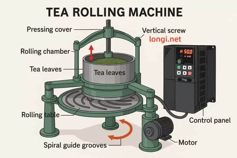
Variable frequency drives (VFDs) are critical components in industrial automation, enabling precise control of motor speed and torque to enhance efficiency and performance. The V680 series VFD, produced by Shenzhen Tai Da Holdings, is a high-performance model widely used in applications such as manufacturing, HVAC systems, and conveyor operations. However, like all sophisticated electronic devices, it may encounter faults that disrupt operations. One common issue is the “E-09” fault code, which indicates an undervoltage condition. This article provides a comprehensive analysis of the E-09 fault’s mechanisms, implications, diagnostic procedures, solutions, and preventive strategies, drawing from technical insights and industry resources.

E-09

Technical Background of the V680 Series VFD

Role of VFDs

VFDs regulate the speed and torque of AC motors by adjusting the frequency and voltage of the power supplied. This capability optimizes energy consumption, reduces mechanical stress, and enhances process control in industrial settings. The V680 series, with its advanced vector control algorithms, is designed for demanding applications requiring high reliability and precision.

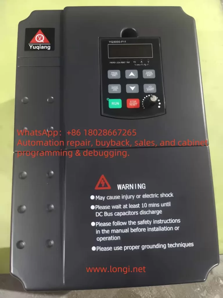
V680 Series Specifications

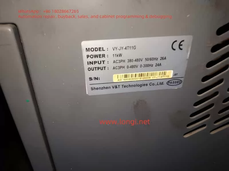
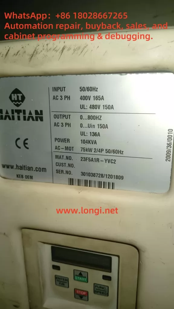
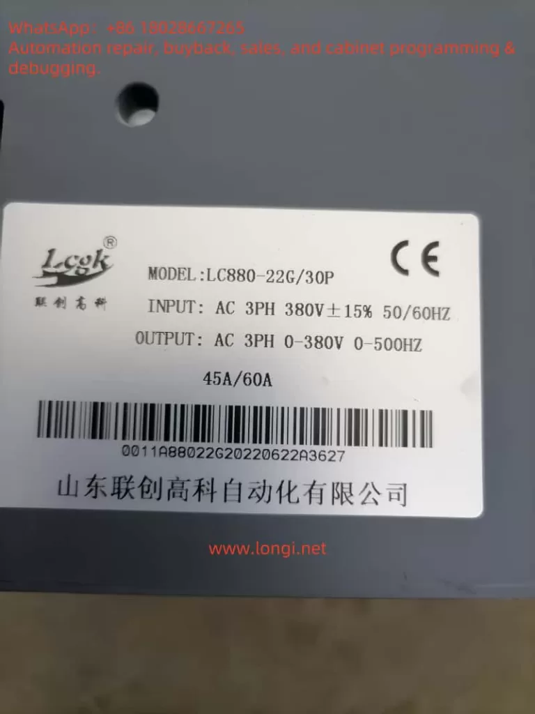
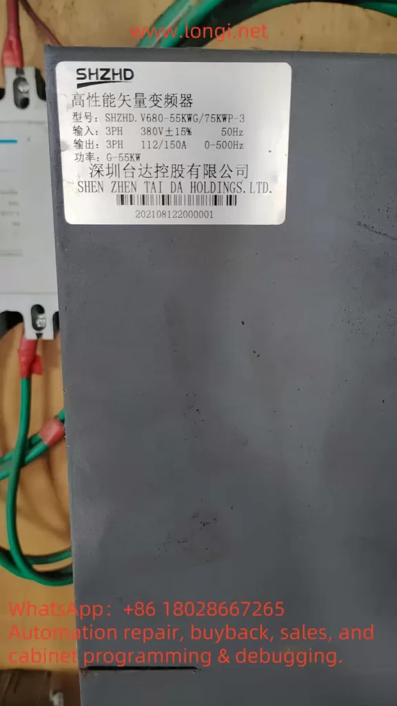
Based on available information, the V680 series (model: SHZHD.V680-55KW/75KWP-3) has the following key specifications:

ParameterSpecification
Input3-phase, 380V ±15%, 50Hz
Output3-phase, 112/150A, 0-500Hz
PowerG-55kW
ManufacturerShenzhen Tai Da Holdings Co., Ltd.

The input voltage range of 323V to 437V is critical for understanding the E-09 fault, as voltages below 323V trigger undervoltage protection.

Definition and Implications of the E-09 Undervoltage Fault

Definition

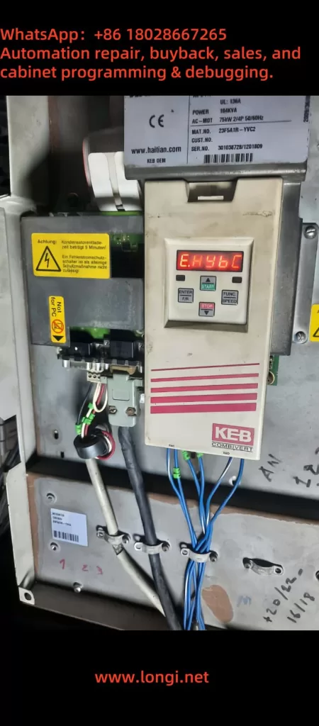
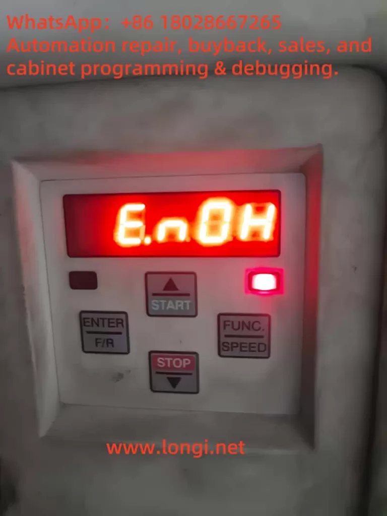
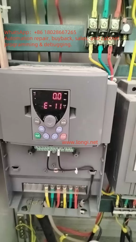
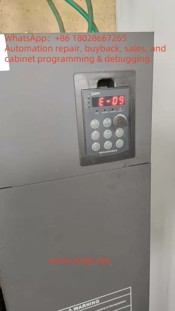
The E-09 fault code signifies that the VFD’s input voltage has fallen below the minimum threshold required for safe operation, typically around 323V for a 380V system. This undervoltage condition prompts the VFD to halt operation to protect itself and the connected motor, displaying “E-09” on the control panel.

Implications

The E-09 fault can have significant consequences:

  • Operational Downtime: The VFD’s shutdown halts motor operation, disrupting production processes and potentially causing financial losses in industries reliant on continuous operation.
  • Component Wear: Prolonged undervoltage can stress electrolytic capacitors and other components, reducing their lifespan and increasing maintenance costs.
  • Performance Issues: In applications requiring precise motor control, such as conveyor systems, undervoltage may lead to erratic motor behavior, compromising product quality.

Mechanisms Behind the E-09 Undervoltage Fault

VFD Operational Principles

A VFD converts input AC power to DC through a rectifier, stores it in a DC bus with capacitors, and then inverts it back to AC with adjustable frequency and voltage to drive the motor. The DC bus voltage, typically around 520V for a 380V input, is crucial for stable operation. A drop in input voltage reduces the DC bus voltage, triggering the E-09 fault if it falls below the undervoltage threshold (approximately 60% of nominal, or ~312V DC).

Causes of Undervoltage

The E-09 fault may result from several factors:

  1. External Power Supply Instability:
    • Grid Fluctuations: Variations in the utility power supply, such as voltage sags or outages, can lower the input voltage.
    • Heavy Load Demands: Simultaneous operation of high-power equipment may cause voltage drops.
    • Phase Loss: Loss of one phase in a three-phase system increases DC bus ripple and may trigger undervoltage protection.
  2. Internal Component Failures:
    • Capacitor Degradation: Electrolytic capacitors in the DC bus may lose capacity over time, failing to smooth voltage fluctuations.
    • Rectifier Issues: Damaged diodes or rectifiers in the power conversion circuit can impair voltage regulation.
    • Pre-Charge Circuit Problems: Faulty pre-charge relays or resistors can prevent proper DC bus charging, especially during startup.
  3. Wiring and Connection Issues:
    • Loose or corroded connections increase resistance, causing voltage drops at the VFD’s input.
    • Improper wiring, as outlined in the V680 manual’s connection diagrams, can exacerbate the issue.
  4. Environmental Factors:
    • High temperatures or humidity can degrade component performance, indirectly contributing to undervoltage.
    • Dust accumulation may cause overheating or short circuits, affecting voltage stability.
  5. Sensing Circuit Malfunction:
    • A faulty DC voltage sensing circuit within the VFD may incorrectly detect low voltage, causing nuisance trips.

Trigger Mechanism

The VFD continuously monitors the DC bus voltage. When it detects a voltage below the undervoltage threshold, it activates the E-09 fault, halting operation. For the V680 series, this threshold is likely set to protect against voltages below 323V AC, corresponding to a DC bus voltage of approximately 312V. The fault may reset automatically after 5 seconds if the voltage stabilizes, as noted in some Tai Da VFD documentation.

Diagnostic Steps for the E-09 Fault

Diagnosing the E-09 fault requires a systematic approach to identify the root cause:

  1. Verify Input Voltage:
    • Measure the input voltage at the VFD’s terminals using a multimeter, ensuring it is within 380V ±15% (323V–437V).
    • Check all three phases for balance and absence of phase loss.
    • If the voltage is low, investigate upstream power supply issues with the utility provider.
  2. Inspect Internal Components:
    • Power down the VFD and inspect for visible signs of damage, such as capacitor leakage, bulging, or burn marks on the rectifier or control board.
    • Test capacitors and rectifiers with appropriate equipment, if qualified, or consult a technician.
    • Check the pre-charge circuit for relay or resistor functionality.
  3. Examine Wiring and Connections:
    • Refer to the V680 manual’s wiring diagrams to verify correct connections.
    • Tighten all terminal connections and inspect cables for damage or corrosion.
  4. Evaluate Environmental Conditions:
    • Ensure the VFD operates within the recommended temperature (-10°C to +40°C) and humidity (≤95% RH, non-condensing) ranges.
    • Clean dust from the VFD and improve ventilation if necessary.
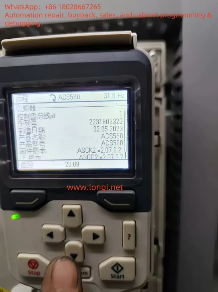
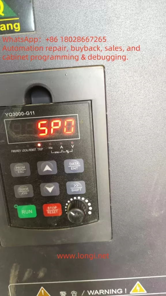
  5. Review Control Panel Diagnostics:
    • Note any additional indicators on the control panel, such as “Hz” or “RUN” status, to contextualize the fault.
    • Cross-reference the E-09 code with the manual’s fault table, if available, for specific guidance.
  6. Test DC Bus Voltage:
    • If equipped, measure the DC bus voltage to confirm it aligns with the expected value (~520V for 380V input). Discrepancies may indicate internal issues or sensing circuit faults.

Solutions to Resolve the E-09 Undervoltage Fault

Immediate Corrective Actions

  1. Reset the Fault:
    • Power cycle the VFD by turning off the main supply, waiting a few minutes, and restarting. Alternatively, use the control panel’s reset function.
    • Verify if the fault clears after voltage stabilization.
  2. Address Power Supply Issues:
    • Install a voltage stabilizer or uninterruptible power supply (UPS) to maintain consistent 380V input.
    • Use a line reactor or isolation transformer to mitigate voltage sags and surges.
    • Coordinate with the utility provider to adjust transformer tap settings or resolve grid issues.
  3. Repair Internal Components:
    • Replace faulty capacitors, rectifiers, or pre-charge circuit components, adhering to the manual’s maintenance guidelines and using manufacturer-approved parts.
    • Engage a qualified technician for complex repairs to avoid further damage.
  4. Correct Wiring Issues:
    • Tighten loose connections and replace damaged cables as per the manual’s wiring specifications.
    • Ensure proper grounding to prevent electrical interference.
  5. Mitigate Environmental Factors:
    • Relocate the VFD to a cooler, drier location or enhance ventilation with fans or air conditioning.
    • Install dust filters to protect internal components.

Long-Term Preventive Measures

  1. Regular Maintenance:
    • Schedule monthly or quarterly inspections to check wiring, components, and cleanliness, as recommended in the V680 manual.
    • Monitor capacitor health and replace them proactively based on their rated lifespan.
  2. Power Protection Systems:
    • Deploy surge protectors, phase loss relays, and dynamic voltage restorers to safeguard against power anomalies.
    • Consider a static var compensator for facilities with frequent voltage sags.
  3. Environmental Optimization:
    • Maintain a controlled environment with stable temperature and humidity levels.
    • Enclose the VFD in a protective cabinet if exposed to harsh conditions.
  4. Operator Training:
    • Train personnel to recognize E-09 and other fault codes, enabling quick initial responses.
    • Provide access to the V680 manual for reference during troubleshooting.
  5. Manufacturer Support:
    • Establish a relationship with Shenzhen Tai Da Holdings’ customer service for technical support and access to firmware updates or replacement parts.
SHZHD.V680

Comparison with Other VFD Faults

To contextualize the E-09 fault, consider other common VFD faults:

Fault CodeDescriptionCommon Causes
E-10OvervoltageExcessive input voltage, regenerative energy
E-06OvercurrentMotor overload, short circuit
E-04OverheatingPoor ventilation, high ambient temperature
E-07Ground FaultMotor or wiring insulation failure

While E-09 is specific to undervoltage, its diagnostic and resolution strategies overlap with these faults, particularly in checking power supply and environmental conditions.

Additional Insights from Industry Resources

Research indicates that undervoltage faults, like E-09, are common in VFDs due to their sensitivity to power quality. , undervoltage protection is typically based on DC bus voltage, which for a 380V system should be around 520V. A drop to 60% of this value (~312V) triggers the fault. The site also highlights phase loss as a frequent cause.

Troubleshooting Flowchart

Below is a simplified flowchart for addressing the E-09 fault:

Start
  ↓
Check Input Voltage (380V ±15%)
  ↓
Voltage Normal? → Yes → Inspect Internal Components
  ↓ No
Adjust Power Supply (Stabilizer/UPS)
  ↓
Fault Cleared? → Yes → End
  ↓ No
Inspect Wiring/Connections
  ↓
Connections Secure? → Yes → Check Environment
  ↓ No
Tighten/Replace Wiring
  ↓
Environment Normal? → Yes → Reset Fault
  ↓ No
Improve Ventilation/Cleanliness
  ↓
Fault Cleared? → Yes → End
  ↓ No
Contact Manufacturer Support

Conclusion and Best Practices

The E-09 undervoltage fault in the V680 series VFD is a manageable issue when approached systematically. By identifying whether the cause is external power instability, internal component failure, wiring issues, or environmental factors, users can implement targeted solutions to restore operation. The V680 manual is a critical resource, providing wiring diagrams, safety guidelines, and maintenance protocols to support troubleshooting.

Best practices include:

  • Stable Power Supply: Use voltage stabilizers and UPS systems to ensure consistent 380V input.
  • Routine Maintenance: Conduct regular inspections to detect and address component wear early.
  • Environmental Control: Maintain optimal operating conditions to protect the VFD.
  • Operator Training: Equip staff with the knowledge to respond to fault codes promptly.
  • Manufacturer Support: Leverage Shenzhen Tai Da Holdings’ expertise for complex issues.

By adopting these strategies, users can minimize downtime, extend the VFD’s lifespan, and ensure reliable performance in industrial applications. This comprehensive approach not only resolves the E-09 fault but also enhances overall system resilience against future power-related issues.

Posted on

V&T VY-JY Injection Molding Machine Dedicated Asynchronous Servo Drive User Guide

I. Product Overview and Core Advantages

1. Product Positioning

The VY-JY series is a high-performance asynchronous servo drive specifically designed for the hydraulic systems of injection molding machines. It employs sensorless vector control technology to adjust the speed of the oil pump motor to match the flow/pressure requirements of the injection molding process, eliminating overflow energy consumption and achieving a 25%-70% energy savings rate.

2. Technical Highlights

Dual Vector Control Modes:

  • Vector Control 1: 180% starting torque at 0.50 Hz, speed regulation range of 1:100, and speed stability accuracy of ±0.5%.
  • Vector Control 2: 180% starting torque at 0.25 Hz, speed regulation range of 1:200, and speed stability accuracy of ±0.2% (comparable to DC motor control).

Core Energy-Saving Technologies for Injection Molding:

  • Real-time reception of injection molding machine pressure/flow signals to dynamically adjust oil pump speed, eliminating high-pressure overflow losses.
  • Support for 3 customizable flow-pressure curves (4-point, 5-segment correction) to adapt to different mold processes.

High Reliability Design:

  • Wide voltage range (DC 360-720V) and triple-protection technology (PCB coating, copper busbar plating, and sealed components).
  • Short-term overload capacity: 200% rated load for 0.5 seconds, 150% rated load for 1 minute.
V&T VY-JT

II. Installation and Wiring Specifications

1. Installation Environment Requirements

ParameterStandard ValueRemarks
Ambient Temperature-10°C to +40°CDerate rated current by 1% for every 1°C increase above 40°C
Humidity5% to 95%Condensation prohibited
Altitude≤2000 metersDerate by 1% for every 100 meters above 1000 meters
Vibration≤15 m/s² (200-500 Hz)Avoid metal dust/corrosive gases

2. Main Circuit Wiring Essentials

  • Power Terminals: Connect R/L1, S/L2, and T/L3 to a three-phase power supply (380-480V ±15%).
  • Motor Terminals: Connect U/T1, V/T2, and W/T3 to the motor. Reverse connection or short-circuiting is strictly prohibited.
  • Brake Resistor:
    • Models from 11-15 kW come with a built-in brake unit (terminals B1/B2) as standard.
    • Models above 18.5 kW require an optional brake resistor with a resistance value greater than the lower limit specified in the manual (e.g., ≥7Ω for a 55 kW model).
  • Grounding Requirements:
    • The PE terminal must be independently grounded (resistance <10Ω).
    • The grounding wire diameter should be selected based on power rating (e.g., 35 mm² for a 90 kW model).

3. Control Circuit Wiring

  • Analog Inputs:
    • AI1/AI2: 0-10V or 0-20mA (selectable via jumpers).
    • AI3: -10V to +10V (supports direction control).
  • Digital Inputs: X1-X7 support 24VDC switch/pulse signals (up to 50 kHz).
  • Communication Interface: Dual 485 ports (Modbus-RTU protocol), supporting master-slave control and parameter reading/writing.

⚠️ Safety Warning:

  • Separate or vertically cross the main and control circuit wiring to prevent interference.
  • When the motor cable exceeds 100 meters, an output reactor must be installed, and the carrier frequency must be reduced (≤5 kHz).

III. Operation Procedures and Parameter Settings

1. Initial Power-On Operation Procedure

mermaidgraph TD    A[Power On] --> B[Restore Factory Parameters P0.01=3]    B --> C[Set Motor Nameplate Parameters P9.00-P9.04]    C --> D{Can the Load Be Disconnected?}    D -->|Yes| E[Rotating Auto-Tuning P9.15=2]    D -->|No| F[Stationary Auto-Tuning P9.15=1]    E & F --> G[Press RUN Key to Execute Auto-Tuning]    G --> H[Set Operating Frequency P0.05]    H --> I[Select Control Mode P0.03]    I --> J[Start Operation]

2. Injection Molding-Specific Function Configuration

Energy-Saving Mode Activation (H0 Group Parameters):

Function CodeNameExample SettingFunction Description
H0.00Plastic Machine Frequency Setting Mode Selection1Enable User-Defined 1
H0.03Plastic Machine Frequency Setting User-Defined 10000Both Flow and Pressure Signals Are Valid
H0.09-H0.16Flow-Frequency Curve 1A0=0%, B0=0%
A3=100%, B3=100%
4-Point Linear Mapping

Soft PLC Logic Programming (H1 Group Parameters):
Perform logical operations (AND/OR/NOT) or mathematical operations (addition, subtraction, multiplication, division) on digital/analog quantities, and output the results to the Y terminal or control frequency.
Example: H1.00=111 enables 3-channel logical operations, and H1.01=123 sets X1/X2/X3 as input sources.

3. Key Operating Parameters

Parameter GroupFunction CodeNameRecommended ValueImpact
P0P0.08Acceleration Time 020.0sExtend for large inertia loads
P3P3.05Stopping Method2 (Deceleration + DC Braking)Prevent pump reversal
PAPA.00Carrier Frequency8.0kHzReduce for high-frequency noise-sensitive applications

IV. Fault Diagnosis and Maintenance

VY-JY-4T11G

1. Common Fault Handling

Fault CodeMeaningTroubleshooting Steps
E.OC1Acceleration Overcurrent1. Check for motor cable short-circuits.
2. Extend acceleration time.
E.OUDeceleration Overvoltage1. Check brake resistor value.
2. Enable energy dissipation braking.
E.PTCMotor Overheating1. Check PTC sensor wiring.
2. Reduce load rate.

2. Regular Maintenance Items

CycleItemOperation
MonthlyRadiator CleaningUse compressed air to remove dust (operate with power off).
Semi-AnnuallyElectrolytic Capacitor InspectionCheck for bulging/leakage; replace if capacity drops by ≥20%.
AnnuallyInsulation Resistance TestMotor winding-to-ground insulation resistance ≥5MΩ (500VDC).

🔧 Maintenance Note: Wait 10 minutes after power-off (until the CHARGE light goes out) before operating to ensure bus capacitor discharge is complete.

V. Energy-Saving Benefit Analysis

Energy Savings Rate Calculation Model:
Energy Savings Rate=(1−Servo System Energy ConsumptionPower Frequency System Energy Consumption​)×100%

Influencing Factors:

  • Mold Process Speed Value: Energy savings rate ≈70% at 30% speed and ≈25% at 90% speed.
  • Net Cooling Time: Energy savings rate decreases without cooling time.

✅ Case Study: Post-retrofit measurements for a 220T injection molding machine at a certain factory:

  • Power Frequency Monthly Energy Consumption: 18,600 kWh
  • Servo Monthly Energy Consumption: 7,440 kWh
  • Energy Savings Rate: 60%

VI. Appendix: Key Parameter Quick Reference Table

CategoryFunction CodeNameFactory Default
Motor ParametersP9.02Rated Speed1500 rpm
Communication SettingsPC.02Local Address1
Protection FunctionsPA.21Auto-Reset Count0 (Disabled)
Plastic Machine-SpecificH0.34AI1/AI2 Extended Input Enable0 (Disabled)

This guide covers the entire process of installation, parameter configuration, fault handling, and energy-saving optimization. It is compiled in conjunction with Chapter 9 (Injection Molding Energy-Saving Principles) and Chapter 10 (Technical Features) of the manual to ensure users quickly master the core applications of the VY-JY series. Before operation, be sure to read the manual’s “Safety Precautions” (Pages 14-16) in detail. Unauthorized operation is strictly prohibited.

Posted on

Rockwell PowerFlex 400 Series Inverter FAULT 008 Troubleshooting and Resolution

Key Points:

  • FAULT 008, known as “Heatsink Over Temperature,” indicates that the inverter’s heatsink temperature has exceeded safe limits, likely to protect the device from overheating damage.
  • Common causes include blocked or dirty heatsink fins, high ambient temperatures, or cooling fan failure.
  • Troubleshooting involves cleaning the heatsink, verifying ambient temperature, and checking fan operation.
  • Preventive measures include regular maintenance, temperature monitoring, and proper installation to ensure adequate airflow.

What is FAULT 008?
When a Rockwell PowerFlex 400 series inverter displays FAULT 008, labeled “Heatsink OvrTmp,” it signals that the heatsink temperature has surpassed its safe operating threshold. This fault halts the inverter to prevent damage to internal components, such as the power electronics. The control panel will show “FAULT 008 Heatsink Ovrtmp” with a yellow or orange indicator light, alerting the user to take immediate action.

fault  008

Why Does It Happen?
The overheating of the heatsink can stem from several issues:

  • Blocked or Dirty Heatsink Fins: Dust or debris accumulation reduces the heatsink’s ability to dissipate heat.
  • High Ambient Temperature: Operating environments exceeding 40°C (104°F) for IP 30/NEMA 1/UL Type 1 installations or 50°C (122°F) for open-type installations can overwhelm the cooling system.
  • Fan Failure: A malfunctioning or stopped cooling fan disrupts airflow, causing heat buildup.

How to Address It?
To resolve FAULT 008, follow these steps:

  • Clean the Heatsink: Power off the inverter, open the enclosure, and use compressed air or a soft brush to remove dust or debris from the heatsink fins.
  • Check Ambient Temperature: Measure the surrounding temperature to ensure it is within the specified limits. If too high, improve ventilation or relocate the inverter.
  • Inspect the Fan: Verify that the cooling fan is operational. Replace it if it’s not functioning, using a compatible part.

Preventing Future Issues
Regular maintenance, such as cleaning the heatsink and monitoring ambient conditions, along with proper installation to ensure good airflow, can help avoid this fault in the future.


Comprehensive Analysis and Solutions for FAULT 008 in Rockwell PowerFlex 400 Series Inverters

Introduction

The Rockwell PowerFlex 400 series inverters are widely used in industrial automation for controlling AC motor speed and torque, particularly in applications like fans and pumps. Known for their reliability and versatility, these inverters occasionally encounter faults that require prompt attention. One such fault, FAULT 008 (Heatsink Over Temperature), indicates that the inverter’s heatsink has exceeded its safe temperature threshold. This article provides a detailed exploration of FAULT 008, including its definition, causes, troubleshooting steps, solutions, and preventive measures to ensure reliable operation.

This content is based on information from the Rockwell PowerFlex 400 User Manual and fault code documentation, ensuring accuracy and relevance for users addressing this issue.

1. Understanding FAULT 008

FAULT 008, labeled “Heatsink OvrTmp,” is a critical fault in the PowerFlex 400 series that occurs when the heatsink temperature exceeds the safe operating limit. The heatsink is a vital component responsible for dissipating heat generated by the inverter’s power electronics, such as IGBT modules. When this fault is triggered, the inverter halts operation to prevent thermal damage, displaying “FAULT 008 Heatsink Ovrtmp” on the control panel with a yellow or orange indicator light. This fault is classified as an Auto-Reset/Run type, meaning it may attempt to reset automatically if configured (via parameters A092 and A093), provided the underlying issue is resolved.

2. Causes of FAULT 008

Several factors can lead to the heatsink overheating, triggering FAULT 008. The primary causes include:

2.1 Blocked or Dirty Heatsink Fins

The heatsink relies on air circulation to dissipate heat. Dust, oil, or debris accumulation on the fins can obstruct airflow, significantly reducing cooling efficiency. This is particularly common in dusty industrial environments.

2.2 High Ambient Temperature

The PowerFlex 400 has specific environmental temperature limits:

  • IP 30/NEMA 1/UL Type 1 Installations: Maximum ambient temperature of 40°C (104°F).
  • Open-Type Installations: Maximum ambient temperature of 50°C (122°F).
    If the operating environment exceeds these limits, the heatsink may struggle to maintain safe temperatures.

2.3 Cooling Fan Failure

The inverter’s cooling fan ensures adequate airflow over the heatsink. A malfunctioning fan—due to mechanical issues (e.g., worn bearings), electrical faults, or blockages—can lead to insufficient cooling and overheating.

2.4 Excessive Load or Duty Cycle

Running the inverter at or beyond its rated capacity for extended periods generates excessive heat, which the cooling system may not handle effectively.

2.5 Poor Ventilation

Improper installation, such as placing the inverter in a confined space or obstructing air inlets/outlets, can trap heat and cause the heatsink to overheat.

CauseDescriptionImpact
Blocked Heatsink FinsDust or debris reduces airflow, impairing heat dissipation.Heatsink temperature rises.
High Ambient TemperatureEnvironment exceeds 40°C (IP 30) or 50°C (Open type).Cooling system overwhelmed.
Cooling Fan FailureFan stops or operates inefficiently, reducing airflow.Inadequate heatsink cooling.
Excessive LoadProlonged high-load operation generates excessive heat.Heatsink temperature exceeds limits.
Poor VentilationRestricted airflow due to improper installation or obstructions.Heat accumulation.
powerflex 400

3. Troubleshooting FAULT 008

Resolving FAULT 008 requires a systematic approach to identify and address the root cause. Below are the recommended steps:

3.1 Inspect and Clean Heatsink Fins

  • Procedure: Disconnect the inverter from power, open the enclosure, and inspect the heatsink fins for dust, oil, or debris.
  • Tools: Use compressed air or a soft brush to clean the fins, ensuring no contaminants remain.
  • Precautions: Avoid introducing foreign objects into the inverter during cleaning.

3.2 Verify Ambient Temperature

  • Procedure: Measure the ambient temperature around the inverter using a thermometer.
  • Standards:
  • IP 30/NEMA 1/UL Type 1: ≤40°C (104°F).
  • Open Type: ≤50°C (122°F).
  • Action: If the temperature exceeds limits, enhance ventilation (e.g., add fans or air conditioning) or relocate the inverter to a cooler area.

3.3 Check Cooling Fan Operation

  • Procedure:
  • Power on the inverter and confirm the fan is running by listening for operation or checking for airflow.
  • Inspect for blockages or damage to the fan blades.
  • Listen for unusual noises indicating bearing wear or mechanical issues.
  • Action: Replace a faulty fan with a genuine Rockwell part, following the manual’s replacement instructions.

3.4 Evaluate Load and Duty Cycle

  • Procedure:
  • Check the inverter’s load to ensure it does not exceed the rated capacity.
  • Review parameter A089 [Current Limit 1] to confirm it matches the motor’s specifications.
  • Action: Reduce the load or adjust parameters if overloading is detected. Consider upgrading to a higher-capacity inverter if necessary.

3.5 Ensure Adequate Ventilation

  • Procedure:
  • Verify that the inverter has sufficient clearance (at least 10-15 cm) around air inlets and outlets.
  • Check for obstructions blocking airflow.
  • Action: Reposition the inverter or remove obstructions to improve ventilation.

4. Solutions and Preventive Measures

4.1 Solutions

Based on the troubleshooting results, apply the following solutions:

  • Dirty Heatsink Fins: Clean thoroughly to restore airflow.
  • High Ambient Temperature: Install cooling equipment or relocate the inverter.
  • Fan Failure: Replace the fan with a compatible part.
  • Excessive Load: Adjust load or parameters, or upgrade the inverter.
  • Poor Ventilation: Reconfigure the installation to ensure proper airflow.

4.2 Preventive Measures

To minimize the risk of FAULT 008 recurring, adopt these practices:

  • Regular Maintenance:
  • Clean heatsink fins and inspect fans every 3-6 months, adjusting frequency based on environmental conditions.
  • Replace aging fans proactively to avoid unexpected failures.
  • Environmental Monitoring:
  • Use temperature sensors to monitor ambient conditions and alert for exceedances.
  • Install cooling systems in high-temperature environments.
  • Load Management:
  • Ensure the inverter’s capacity matches the application’s demands.
  • Avoid prolonged operation at maximum load.
  • Proper Installation:
  • Adhere to the PowerFlex 400 User Manual’s installation guidelines, ensuring adequate clearance and ventilation.
  • Avoid enclosed or poorly ventilated spaces.

5. Conclusion

FAULT 008 (Heatsink Over Temperature) in the Rockwell PowerFlex 400 series inverters is a critical issue that requires immediate attention to prevent equipment damage. By understanding its causes—such as blocked heatsink fins, high ambient temperatures, or fan failures—users can systematically troubleshoot and resolve the fault. Implementing regular maintenance, monitoring environmental conditions, and ensuring proper installation are key to preventing recurrence. This comprehensive guide equips users with the knowledge and steps needed to maintain reliable and efficient operation of their PowerFlex 400 inverters.

Posted on

Analysis and Solution for ABB ACS580 Fault 4310 (A4B0): Power Unit Module Temperature Excessive

Introduction

Variable frequency drives (VFDs) like the ABB ACS580 are vital in industrial automation, offering precise control over motor speed and torque for applications such as pumps, fans, and conveyors. These drives enhance efficiency but can encounter faults that disrupt operations. One common issue is fault code 4310, also known as A4B0, which signals that the power unit module temperature has exceeded safe limits. This article explores the causes, mechanisms, troubleshooting steps, and preventive measures for this fault, providing a comprehensive guide for users and maintenance personnel to ensure reliable operation.

4310 FAULT

Understanding Fault 4310 (A4B0)

Fault 4310 (A4B0) in the ABB ACS580 indicates that the temperature of the power unit module, which contains insulated gate bipolar transistors (IGBTs) responsible for converting DC to AC for motor control, has become excessively high. IGBTs generate heat during operation due to switching and conduction losses. When the temperature exceeds a safe threshold (typically 90-100°C, depending on the model), the drive triggers this fault to halt operation and protect internal components from thermal damage. The fault code appears on the control panel, often with auxiliary codes indicating specific issues, such as overheating in the U, V, or W phase, or environmental factors.

Causes of Fault 4310 (A4B0)

Several factors can contribute to the power unit module overheating, including:

  1. High Ambient Temperature: The ACS580 is designed to operate in environments up to 40°C (104°F). If the surrounding temperature exceeds this, the cooling system may struggle to dissipate heat effectively, especially in enclosed or poorly ventilated spaces.
  2. Insufficient Cooling: The drive relies on cooling fans to draw air over heat sinks attached to the power modules. Fan failures due to worn bearings, electrical issues, or blocked airflow paths (e.g., by debris or improper placement) reduce cooling efficiency.
  3. Dust Accumulation: In industrial environments, dust and particulate matter can accumulate on heat sinks, acting as an insulator and hindering heat transfer. This reduces the cooling system’s effectiveness.
  4. Overloading: Operating the drive beyond its rated power capacity causes the IGBTs to generate excessive heat. This can occur if the connected motor or load exceeds the drive’s specifications.
  5. Incorrect Installation: ABB provides specific installation guidelines, including minimum clearance distances for airflow. Installing the drive in a confined space or near heat-generating equipment can trap heat, leading to overheating.

Mechanism of Fault 4310 (A4B0)

The ACS580 is equipped with temperature sensors that continuously monitor the power unit module’s temperature. These sensors are integrated into the drive’s control system, which compares the measured temperature against a predefined limit. If the temperature exceeds this threshold, the drive activates fault 4310 (A4B0) to stop operation, preventing damage to the IGBTs and other components. The fault may be accompanied by auxiliary codes that pinpoint the issue, such as specific phase overheating (U, V, or W), environmental temperature issues, or internal component failures. This protective mechanism ensures the drive’s longevity and reliability by addressing thermal risks promptly.

Troubleshooting and Solutions

To resolve fault 4310 (A4B0), follow these systematic steps:

  1. Check Ambient Temperature: Measure the temperature near the drive using a reliable thermometer. Ensure it is within the 0-40°C range specified for the ACS580. If the temperature is too high, improve ventilation by adding fans or air conditioning, or relocate the drive to a cooler area.
  2. Inspect Cooling Fans: With the drive powered off, check all cooling fans for proper operation. Look for signs of damage, loose connections, or worn bearings. Listen for unusual noises indicating fan issues. Replace faulty fans with ABB-approved components and verify that the fan direction supports proper airflow.
  3. Clear Airflow Paths: Ensure that air intake and exhaust vents are free from obstructions such as cable bundles, dust filters, or other objects. Remove any covers or panels that restrict airflow and reposition items as needed.
  4. Clean Heat Sinks: Disconnect the drive from power and use compressed air or a soft brush to remove dust and debris from the heat sinks. Avoid using liquids that could leave residues or damage components. Ensure the heat sinks are clean to maximize heat transfer.
  5. Verify Load: Compare the drive’s rated power (listed on its nameplate) with the motor’s specifications and the actual load. If the load exceeds the drive’s capacity, consider reducing the load or upgrading to a higher-capacity drive model.
  6. Review Installation: Consult the ABB ACS580 installation manual to confirm that the drive is mounted correctly. Ensure there is at least 100 mm (4 inches) of clearance on all sides for airflow. Verify that the drive is not exposed to direct sunlight or other heat sources.
  7. Reset the Drive: After addressing the above issues, reset the drive by cycling power or using the reset button on the control panel. Monitor the drive’s operation to ensure the fault does not recur. Check the event log for any additional diagnostic information.
ACS580

Troubleshooting Steps Table

StepActionNotes
Check Ambient TemperatureMeasure temperature near the driveEnsure within 0-40°C; improve ventilation if needed
Inspect Cooling FansCheck for operation, damage, or noiseReplace faulty fans; confirm correct airflow direction
Clear Airflow PathsRemove obstructions from ventsEnsure no cables or debris block intake/exhaust
Clean Heat SinksUse compressed air or brush to cleanPower off drive; avoid liquids
Verify LoadCompare drive and motor ratingsReduce load or upgrade drive if necessary
Review InstallationCheck clearance and placementEnsure 100 mm clearance; avoid heat sources
Reset DriveCycle power or use reset buttonMonitor for fault recurrence

Preventive Measures

To minimize the risk of fault 4310 (A4B0), implement these preventive strategies:

  1. Regular Maintenance Schedule: Establish a maintenance routine, inspecting and cleaning the cooling system every 6-12 months, depending on the environment’s dust levels. Regular checks prevent dust buildup and ensure fan reliability.
  2. Temperature Monitoring: Utilize the ACS580’s built-in temperature monitoring features (accessible via parameters like 04.11-04.13) to track temperature trends. Set alarms to alert personnel if temperatures approach critical levels, enabling early intervention.
  3. Load Management: Design systems with adequate headroom for peak loads. Avoid operating the drive at or near its maximum capacity for extended periods. Use energy-saving modes or adjust parameters to optimize performance for variable loads.
  4. Proper Installation Practices: Adhere to ABB’s installation guidelines, ensuring proper mounting, electrical connections, and grounding. Maintain specified clearance distances to support airflow and prevent heat buildup.
  5. Environmental Control: In harsh environments (e.g., dusty or hot locations), use NEMA-rated enclosures and maintain air filters. In high-temperature settings, consider additional cooling solutions like heat exchangers or air conditioning.

Preventive Measures Table

MeasureActionFrequency
Regular MaintenanceInspect and clean cooling systemEvery 6-12 months
Temperature MonitoringTrack temperature trends via parametersWeekly or monthly
Load ManagementEnsure load matches drive capacityDuring system design
Proper InstallationFollow ABB guidelines for mountingDuring installation
Environmental ControlUse enclosures, filters, or coolingAs needed per environment

Conclusion

Fault 4310 (A4B0) in the ABB ACS580, indicating excessive power unit module temperature, is a critical issue that demands prompt attention to prevent damage to the drive. By understanding its causes—such as high ambient temperatures, cooling failures, dust accumulation, overloading, or improper installation—users can follow systematic troubleshooting steps to resolve the issue. Preventive measures, including regular maintenance, temperature monitoring, load management, and proper installation, are essential for minimizing the risk of recurrence. Familiarity with the drive’s documentation, such as the user manual and fault tracing guide, and ongoing training for maintenance personnel further enhance operational reliability. By addressing this fault effectively, users can ensure the ACS580 operates efficiently, supporting uninterrupted industrial processes.

Posted on

Fault Analysis and Solutions for SPO Fault in Yuqiang Frequency Converter YQ3000-G11

Introduction

In industrial automation and control systems, Variable Frequency Drives (VFDs) are indispensable core devices. They convert fixed-frequency AC power into variable-frequency AC power, enabling precise control over the speed and torque of AC motors. This functionality is crucial in various fields, including manufacturing, Heating, Ventilation, and Air Conditioning (HVAC), and water pump systems. The Yuqiang YQ3000-G11 frequency converter, manufactured by Foshan Yuqiang Electromechanical Co., Ltd., is widely popular in the market for its reliability and high performance. However, like any electronic device, it may encounter faults, with the SPO fault (Output Phase Loss) being one of the common issues faced by YQ3000-G11 users. This article delves into the nature, causes, solutions, and preventive measures of the SPO fault, providing comprehensive guidance to ensure efficient and stable system operation.

FAULT SPO

Definition and Manifestation of SPO Fault

The SPO fault is displayed as “SPO” or “5P0” on the control panel of the YQ3000-G11 frequency converter, accompanied by the illumination of the “TRIP” indicator light. This indicates that the frequency converter has detected the absence of at least one phase or severe imbalance in the three-phase (U, V, W) output load. According to the provided diagnostic table (attached “image.png”), the SPO fault is described as “U, V, W phase loss output (or severe three-phase load asymmetry),” advising users to “check output wiring; check motor and cables.” This fault prevents the motor from starting or operating normally, potentially leading to overheating, inefficiency, and even damage to the motor or frequency converter.

In a three-phase power system, the U, V, and W phases must remain balanced to ensure proper motor operation. A phase loss means the absence of voltage or current in one phase, causing an imbalance in the three-phase system. This situation may manifest as:

  • Unstable motor operation, with抖动 (vibration) or abnormal noise.
  • Inability of the motor to reach the expected speed or power output.
  • Automatic shutdown of the frequency converter to protect the system, displaying the SPO fault code.

Nature of SPO Fault

The essence of the SPO fault is the imbalance or absence of three-phase power on the output side of the frequency converter. This anomaly can be caused by several factors:

Wiring Issues:

  • Loose or disconnected output cables, preventing normal power transmission in one phase.
  • Damaged cables, such as wear, burnout, or breakage.
  • Wiring errors, such as incorrect connection of the U, V, W phase sequence or improper connection.

Motor Issues:

  • Open circuit in the motor windings, preventing a complete circuit in one phase.
  • Internal short circuit or insulation damage in the motor, affecting current balance.
  • Loose or damaged motor connection terminals.

Internal Frequency Converter Faults:

  • Damaged Insulated Gate Bipolar Transistor (IGBT) modules, affecting the output of one phase.
  • Control circuit or drive board faults, leading to abnormal output signals.
  • Internal overvoltage or overheating protection triggering, suspending output.

External Factors:

  • Overloading, exceeding the rated capacity of the frequency converter or motor.
  • Environmental factors, such as high temperature, high humidity, or dust accumulation, affecting device performance.
  • Grid voltage fluctuations or interference, potentially indirectly affecting output stability.

Parameter Setting Issues:

  • Improper setting of the phase loss protection threshold in the frequency converter, which may be overly sensitive or incorrectly configured.
  • Mismatch between other parameters (such as current limit or frequency setting) and the actual load.

These causes may occur individually or in combination, leading to the occurrence of the SPO fault. Understanding the nature of the fault helps users quickly locate the problem and take effective measures.

Solutions for SPO Fault

Resolving the SPO fault requires a systematic troubleshooting approach. The following is a detailed diagnostic and repair process:

Step 1: Check Output Wiring

  • Inspect Cable Condition: Carefully examine the U, V, and W phase cables from the frequency converter to the motor for signs of wear, burnout, or breakage.
  • Confirm Secure Connections: Ensure all wiring terminals are tightened and free from looseness or poor contact.
  • Verify Wiring Correctness: Refer to the YQ3000-G11 frequency converter manual (attached “YQ3000-G11 Yuqiang Frequency Converter Manual.pdf”) to confirm the correct connection of the U, V, and W phase sequence.

Step 2: Check Motor

  • Measure Winding Resistance: Use a multimeter to measure the resistance between U-V, V-W, and W-U on the motor. Normally, the resistance of each phase should be close and balanced. Significant differences may indicate an open circuit or damage to the windings.
  • Check for Short Circuits: Test for continuity between each phase and ground to ensure no short circuits exist.
  • Disconnect Motor Test: Disconnect the motor from the frequency converter, run the frequency converter, and measure the output voltage. If the fault disappears, the problem may lie with the motor or load.

Step 3: Verify Frequency Converter Output

  • No-Load Test: With the motor disconnected, start the frequency converter and use a multimeter to measure the output voltage between U-V, V-W, and W-U. Normally, the three-phase voltage should be balanced and conform to the frequency converter specifications.
  • Check for Internal Faults: If the output voltage is unbalanced or missing, it may indicate an IGBT module or control circuit fault. Further hardware inspection or contact with professional maintenance personnel is required at this point.

Step 4: Check Load and Environment

  • Confirm Load Matching: Ensure the connected load is within the rated capacity of the frequency converter and motor. Overloading may trigger protection mechanisms, leading to the SPO fault.
  • Check Environmental Conditions: Confirm that the operating environment temperature and humidity of the frequency converter are within the recommended ranges (refer to the manual). High temperatures or humidity may cause component performance degradation.

Step 5: Check Parameter Settings

  • Enter Parameter Settings: Access the parameter settings menu through the control panel (attached “spo.jpg”) and check parameters related to phase loss protection.
  • Adjust Thresholds: Ensure the phase loss protection threshold is suitable for the current application and adjust it if necessary.
  • Restore Factory Settings: If unsure about the parameter configuration, try restoring the factory settings and reconfiguring them.

Step 6: Seek Professional Help

  • If the above steps fail to resolve the issue, it is recommended to contact us for technical support.
  • For internal hardware faults (such as IGBT module damage), professional technicians using specialized tools are required for repair or replacement.
YQ3000-G11

Fault Troubleshooting Flowchart

StepInspection ContentToolsExpected Results
1Check output cablesVisual inspection, screwdriverCables undamaged, connections secure
2Measure motor winding resistanceMultimeterBalanced three-phase resistance, no short circuits
3Test frequency converter output voltageMultimeterBalanced three-phase voltage, conforming to specifications
4Check load and environmentAmmeter, thermometerLoad within rated range, suitable environment
5Check parameter settingsControl panelCorrect parameter configuration
6Contact professional supportPhone/emailObtain further guidance or repair

Preventive Measures

To reduce the occurrence of SPO faults and extend the service life of the YQ3000-G11 frequency converter, the following preventive measures can be taken:

Regular Maintenance:

  • Inspect and tighten all electrical connections quarterly.
  • Regularly clean the frequency converter and motor to prevent dust accumulation leading to overheating.

Proper Installation:

  • Install the frequency converter in a well-ventilated area away from high temperatures and humidity.
  • Use high-quality cables and connectors that meet specifications.

Load Management:

  • Ensure the motor load is within the rated range to avoid overloading.
  • Use soft start or progressive acceleration functions to reduce electrical shock during startup.

Monitoring System:

  • Install monitoring equipment to track frequency converter performance in real-time and detect anomalies promptly.
  • Regularly review fault logs to address potential issues.

Training and Documentation:

  • Train operators to ensure they are familiar with the correct use and basic troubleshooting of the frequency converter.
  • Keep the frequency converter manual (attached “YQ3000-G11 Yuqiang Frequency Converter Manual.pdf”) for easy reference.

Conclusion

The SPO fault is a common issue that may be encountered during the operation of the Yuqiang YQ3000-G11 frequency converter. Its essence is the absence or imbalance of three-phase power on the output side, which may be caused by wiring issues, motor faults, internal frequency converter problems, or external factors. Through systematic troubleshooting steps, such as checking wiring, motor, output voltage, and parameter settings, users can effectively diagnose and resolve the fault. Regular maintenance, proper installation, and load management are key measures to prevent SPO faults. For further assistance, it is recommended to refer to the manual or contact the technical support team of Yuqiang Electromechanical. By taking these measures, users can ensure the stable operation of the frequency converter system, maximizing equipment lifespan and production efficiency.

Posted on

Tea Rolling Machine: Working Principles and Structural Analysis

The rolling of tea leaves is a critical process in tea production. Its main goal is to twist the leaves into tight strips, rupture some of the leaf cells to promote the release of tea juice, and enhance the aroma and liquor of the tea. The tea rolling machine, as the key mechanical equipment for this task, has gradually replaced traditional manual rolling and is now widely used in the production of black, green, oolong, and other types of tea.


During the tea production process using a tea rolling machine

1. Working Principle of the Tea Rolling Machine

The rolling machine operates by applying pressure between a top press cover and a rotating bottom disc, sandwiching the tea leaves. Through the combined motion of pressing and rotation, the leaves are subjected to extrusion, friction, and kneading forces, causing them to bend, twist, and partially rupture. This helps to form the desired strip shape and allows the internal tea juice to be released.

The main forces at work during rolling include:

  • Shear Force: Facilitates shaping by shearing the leaves between two surfaces;
  • Frictional Force: Generated as the leaves tumble between the disc and the cover, enhancing curl formation;
  • Vertical Pressure: Continuously applied by the top cover to control the rolling intensity and leaf breakage rate.

The rolling process typically follows a sequence of “light pressure – medium pressure – heavy pressure – decompression” to ensure optimal shaping and internal quality.


Schematic diagram of the principle and structure of a tea rolling machine

2. Key Structural Components

Tea rolling machines are robustly built and functionally arranged, typically consisting of the following parts:

  1. Main Frame and Base Support
    Made of cast iron or steel, often tripod-style for excellent stability and vibration resistance.
  2. Rolling Disc (Rotating Plate)
    Located at the base, made from stainless steel or cast aluminum, featuring spiral guide ribs to move the tea in a circular path. The surface is polished for easy cleaning.
  3. Rolling Drum (Barrel)
    A cylindrical chamber fixed above the rotating disc where tea leaves are placed. Smooth and seamless inside for even rolling.
  4. Pressing Cover Mechanism
    Positioned above the barrel, adjustable manually or electrically. The inner surface is curved or grooved to apply even downward pressure. A spring mechanism provides buffering.
  5. Motor and Gearbox Drive
    Drives the rotating disc via belts or gears. Speed is typically reduced to 30–60 rpm for controlled operation.
  6. Control Panel
    May include timers, press height adjustment knobs, power switches, and emergency stops.
  7. Discharge Port
    Once rolling is complete, tea is discharged by lifting the cover or opening a side outlet. Some models have scraper mechanisms for efficient leaf removal.

Schematic diagram of the principle and structure of a tea rolling machine

3. Operational Workflow

1. Leaf Loading

Processed (withered or de-enzymed) leaves are evenly spread into the barrel. No pressure is applied at this stage.

2. Initial Pressing

The press cover is gently lowered to just contact the leaves, stabilizing their position and forming the initial shape.

3. Rolling Phase

The motor activates the rotating disc. Under spiral guidance, the leaves tumble while being pressed by the top cover. This produces combined shearing and extrusion forces. Duration is 3–10 minutes depending on the tea type and batch size.

Rolling can be broken down into:

  • Light rolling (low pressure, low speed)
  • Medium rolling (increased pressure, steady speed)
  • Heavy rolling (max pressure, fixed speed)
  • Final shaping (reduced pressure, slow speed)

4. Discharging

The motor stops, the press cover is lifted or the outlet opened, and the rolled leaves are released.

5. Cleaning and Reset

Residual tea is cleaned off the disc and barrel to prepare for the next batch.


4. Technical Specifications

ItemTypical RangeDescription
Motor Power1.1–3 kWDepends on size and capacity
Rolling Disc Diameter500–1200 mmLarger size accommodates higher loads
Rotation Speed30–60 rpmAdjustable per tea type
Pressing Stroke100–180 mmDefines maximum compression depth
Rolling Time2–15 minutesVaries by tea type
Batch Capacity10–100 kg per batchBased on machine model
Pressing MechanismManual / Electric / PneumaticVaries in precision and efficiency

 tea rolling machine

5. Control Logic Overview

Modern machines include integrated control features such as:

  • Time Setting: Allows rolling duration to be preset;
  • Press Cover Control: Motorized or electric actuator to fine-tune press height and pressure;
  • Speed Regulation: When equipped with an inverter, stepless speed control is achievable;
  • Emergency Stop: Ensures safe halt during abnormal operation;
  • Directional Control: Enables clockwise and counterclockwise rotation alternation for uniform rolling.

These systems promote repeatable, standardized rolling results and reduce operator dependency.


6. Structural Advantages and Craft Adaptability

  1. Durable, Low-Wear Construction: Cast frame design minimizes vibration and extends service life;
  2. Adjustable Pressure Cover: Adapts to different moisture levels and leaf volumes;
  3. Spiral Ribbed Disc: Ensures continuous tumbling and even pressure distribution;
  4. Easy Maintenance: Smooth surfaces reduce cleaning time and prevent residue build-up;
  5. Automation-Friendly: Compatible with external control systems or PLC upgrades.

7. Process Optimization Through Variable Speed Control

In modern tea production, varying tea varieties demand different rolling speeds and pressures. Equipping the machine with a variable frequency drive (VFD) allows flexible speed regulation to match these needs.

By adjusting the disc speed based on tea type (e.g., low speed for green tea, medium for black tea), the shaping and juice extraction can be precisely controlled. Multi-stage speed profiles—such as low for initial shaping, medium for heavy rolling, and low again for final adjustment—are easily managed by inverter systems, ensuring quality and efficiency.

A high-performance inverter like the Longi 900 series offers precise speed control, strong torque at low speeds, smooth acceleration, and good compatibility with industrial tea machinery. This enhances the consistency of rolling results while optimizing energy use and equipment protection.


 tea rolling machine

8. Conclusion

The tea rolling machine is central to the quality of processed tea. Its structural design, technical parameters, and control mechanisms must harmonize with tea characteristics to ensure optimal results.

As electrical and automation technology evolves, upgrading rolling machines with intelligent control and variable speed capability is becoming a standard in tea factory modernization. These advances preserve traditional craftsmanship while enhancing efficiency, consistency, and adaptability in production.


Posted on

High-Precision Spin Coater Design: For Nanometer-Scale PLGA Film Deposition on Top of Micropillar Arrays in PDMS Chips

I. Background and Application Needs

In the fields of cell engineering, biomaterials, and drug delivery systems, high-throughput microstructured chip platforms are becoming a key research tool. Especially platforms combining PDMS micropillar array chips with controlled biodegradable thin films (e.g., PLGA) are widely used in:

  1. Single-cell drug delivery and sensitivity evaluation;
  2. Cell-material interface interaction studies (adhesion, migration, differentiation);
  3. Multi-factor high-throughput screening and biomimetic microenvironment construction;
  4. Precise control of nanoscale drug release behavior.
spin coater

These applications often require construction of highly uniform, nanometer-scale (100–300 nm) functional film layers specifically on the tops of the pillars, with PLGA (poly(lactic-co-glycolic acid)) as the typical material due to its biocompatibility, biodegradability, and tunable release properties.

However, traditional planar spin coaters with vacuum suction platforms are not suitable for achieving uniform nanoscale coatings on non-planar structures like micropillars, especially when coating only the pillar tops. This presents a demand for a specially designed spin coater to meet these challenges.


II. Spin Coating Principle Overview

Spin coating is a widely used technique in microelectronics, optics, and biomaterials for the rapid formation of uniform thin films. The basic steps include:

  1. Dropping solution onto a substrate;
  2. Rapid rotation creates centrifugal force spreading the liquid evenly;
  3. Simultaneous solvent evaporation leads to film formation within seconds.

Based on simplified Meyerhofer’s model, film thickness “h” relates to:

h ∝ (c * μ) / ω^{1/2}

Where:

  • c = solution concentration;
  • μ = viscosity;
  • ω = rotation speed (rpm);

By adjusting these parameters, film thicknesses from tens to hundreds of nanometers can be reliably achieved. For pillar-top coating, this must be combined with specialized jigs, non-vacuum mechanisms, and multi-stage programmatic rotation control.


III. Functional Requirements for the Spin Coater

To satisfy the target application, the spin coater must meet the following specifications:

1. Microstructure-Compatible Platform

  • Substrate size: 55 mm × 55 mm PDMS chip;
  • Non-vacuum clamping to prevent microstructure collapse;
  • Compatible with curved/non-planar substrates for optimal pillar-top coating.

2. Precision Rotational Control

  • Speed range: 100–10,000 rpm;
  • Speed resolution: 1 rpm;
  • Acceleration range: 100–10,000 rpm/s;
  • Multi-stage programmable control (min. 10 segments);
  • Each stage must set: speed, time, acceleration.

3. Nanofilm Thickness Control Module

  • Automated dispensing system (micro syringe pump):
    • Volume range: 0.1–10 μL;
    • Precision: ±0.01 μL;
  • Optional heating lid (to improve uniform solvent evaporation);
  • Environmental sealing (for use inside glovebox);
  • Gas inlet for nitrogen or controlled airflow.

4. Software and Feedback Control

  • Color LCD touchscreen for programming and monitoring;
  • Real-time display of speed, time, temp, steps;
  • At least 20 custom program sets storage;
  • USB export of spin data logs;
  • External sensor interfaces (e.g., ellipsometer, IR monitor).

High-precision spin coater in use.

IV. Key Innovation Highlights

  1. Non-vacuum clamping system:
    • Avoids PDMS micropillar collapse;
    • PTFE precision slot clamp secures the chip without central blockage.
  2. Pillar-top coating optimization:
    • Multi-stage program: pre-spread (low speed), main spin (high speed), dry-out (moderate speed);
    • Sample protocol: 300 rpm (10s) → 2000 rpm (30s) → 1000 rpm (20s).
  3. Micro-volume drop dispensing system:
    • Controlled center-drop of PLGA solution (2–5 wt% in DCM);
    • Precision stage and optional laser alignment.
  4. Anti-edge-thickening logic:
    • Delay spin or pre-wet stage to prevent solution migrating to chip edges.
  5. Open programming interface:
    • Supports MATLAB / Python SDK;
    • Integration with AI or bioassay automation platforms.

V. Workflow Example

  1. Deposit 0.5–2 μL PLGA solution at the center of PDMS chip;
  2. Spin program:
    • Step 1: 300 rpm for 10 s (pre-spread);
    • Step 2: 2000 rpm for 30 s (uniform coating);
    • Step 3: 1000 rpm for 20 s (controlled dry);
  3. Optional: N2 gas flow to assist solvent removal;
  4. Post-process: film thickness validated by ellipsometry or AFM.

VI. Implementation and Materials

  • Control system: STM32/ESP32 + encoder + BLDC driver;
  • Syringe pump: stepper-driven microinjection with replaceable tips;
  • Heating lid: PTFE shell + PTC film heater + PID temp control;
  • Housing: CNC-machined aluminum frame + acrylic protective cover;
  • Chip holder: laser-cut PTFE tray, supporting 3–4 mm thick PDMS chips.

VII. Market Benchmarks and Outlook

Comparison with existing devices:

  • Ossila Advanced Spin Coater (UK);
  • Laurell WS-650 series (USA);
  • MTI VTC-100PA (China);

Our design focuses on the niche need for micropillar-top nanofilm coating in biological applications, filling a gap in existing commercial equipment that primarily supports flat wafer processing.

Future development roadmap includes:

  • Multi-solution switching module (e.g., for combinatorial screening);
  • Vision-assisted chip alignment and coating path planning;
  • Closed-loop AI control based on film thickness feedback.

VIII. Conclusion

This design addresses the unmet need for high-precision nanocoating on micropillar arrays in PDMS chips—especially relevant in single-cell drug screening and cell-material interface studies. By integrating multi-stage programmable spin control, non-vacuum platform, microfluidic injection, and programmable environment conditioning, this spin coater provides a complete solution for researchers working on nanoscale PLGA film deposition in structured biological interfaces.

It is expected to contribute significantly to advanced biomedical research, high-throughput drug screening, and future bioMEMS development.

Posted on

From Power Module Overheating to Advanced Error Code: A Complete Record of Fault Evolution and Troubleshooting for KEB F5 Drive

I. Overview (Introduction)

In industrial drive equipment, the KEB COMBIVERT F5 series inverter is widely used in injection molding machines, elevators, and automation equipment. This series is renowned for its high stability and rich programmable functions. However, precisely due to its complexity, the prompt messages for different types of faults and the error evolution logic often confuse maintenance personnel during drive debugging and repair.

This article takes a real on – site fault as a clue, systematically sorting out the fault causes, parameter checks, and handling procedures from the initial E.OH (power module overheating) → subsequent recovery state E.nOH → E.H496 (extended error code) after replacing the motherboard. It also summarizes a standard troubleshooting logic to help you locate problems more efficiently.

23F5A1R‑YVC2

II. Drive Model and Hardware Background

  • Model: KEB COMBIVERT F5 series (e.g., MAT.NO example: 23F5A1R – YVC2)
  • Power rating: Approximately 75 kW, with an input of 400V AC three – phase, 165A; an output supporting a frequency range of 0 – 800 Hz, and a maximum current of about 150 A (UL 136A)
  • Control board and power board combination: The drive unit is composed of an F5 – General or F5 – Basic control board in combination with a power module. The structured hardware connection is stable.
    This system has undergone initial power – on, multiple fault resets, and motherboard replacement, eventually entering a complex error stage.
CPU board

III. Stage 1: Initial Fault – E.OH (Power Module Overheating)

When the variable – frequency drive detects that the temperature of the power module (heat sink) is too high, it triggers the E.OH error, and at this time, the drive shuts off the output to protect the module. Such errors are often caused by:

  • Blocked or failed cooling fans
  • Severe dust accumulation on the heat sink
  • Excessively high ambient temperature
    According to the documentation (TRD Error codes / KEB F5 manual):
  • For E.OH, one must wait for the internal temperature to drop by at least 3 °C before entering the reset stage.
  • The drive displaying E.nOH indicates that the overheating state has been lifted, and the power module has cooled to a safe level.
    Maintenance operations include:
  • Powering off and waiting for cooling
  • Cleaning the fans and heat sink
  • Checking and improving the ambient ventilation
E.HybC

IV. Stage 2: From E.nOH to Replacing the Control Board

The E.nOH state confirms that the drive has returned to normal. Everything operates normally for a short period.
If the control motherboard is then replaced (e.g., replacing an old faulty board or upgrading the firmware), it may change the internal identification of the drive.
If the drive’s main control board and power board do not correctly match the firmware or power unit identification parameters at this time, new advanced errors may be triggered.

V. Stage 3: E.H496 – Advanced Extended Error Code After Replacing the Motherboard

1. What is E.H496?

E.H496 belongs to the advanced error code (extension error class), specifically indicating a communication or identification anomaly between the control board and the power unit.
In the KEB error manual, it is classified as “power unit changed” or “EEPROM configuration mismatch”. The error prompts may appear in forms such as E.PUCH, E.PUCH, etc., but some new firmware versions may display it as H496.

2. Cause Analysis

  • The control board detects a change in the power unit identification number but the parameters are not synchronized.
  • The power unit configuration saved in the EEPROM does not match.
  • Inconsistent firmware versions lead to a failure in the parameter group SY.3 checksum.
  • The physical connection between the control board and the power board is loose or the communication lines are loose.

VI. Standard Troubleshooting and Handling Procedures 🧭

Step 1: Check the Error History

  • Set the parameter Ud.00 = 660 to enable the LF error log function.
  • View the 0.LF.98 log to analyze the error generation time, type, and sequence.

Step 2: Verify the Connection between the Control Board and the Power Board

  • Check whether the ribbon cables of the X interface are secure and free of oxidation.
  • If there is dust or poor contact, clean and re – plug them.

Step 3: Confirm EEPROM and Firmware Matching

  • Compare the firmware versions of the new and old motherboards with the power board version.
  • If the drive prompts “power unit changed”, write the displayed power unit identification code into the parameter group SY.3 for confirmation.
  • If the SY.3 parameter is written incorrectly, the system will load default values or lock the startup.

Step 4: Perform Synchronization and Initialization

  • If there is an identification anomaly after replacing the control board, write the correct value of SY.3 according to the manual and only reload the power – related parameters.
  • If it still fails, write other values to perform a complete parameter reload (load the KEB default set) and restart the drive.
  • After completing the operations, it is recommended to restart the system (Power – on reset) to ensure synchronization between the drive board and the power module.

Step 5: Re – check Thermal Management and Hardware Status

  • After cooling, power on again to ensure that the fans are working and the ambient temperature is reasonable.
  • Avoid the recurrence of E.OH, which may affect subsequent diagnosis.
E.nOH

VII. Summary Table of Fault Evolution Logic

StageDisplay CodeMeaningPossible CausesMain Handling Measures
InitialE.OH → E.nOHFirst overheating of the power module and return after coolingPoor heat dissipation, high ambient temperatureClean the fans and heat sink, improve ventilation
IntermediateE.nOH state returns to normalNo new errors in the moduleTemporary parameter recovery processNo additional operations required
After replacing the motherboardE.H496 or E.PUCHAdvanced error: Power unit identification anomalyControl board/firmware mismatch, identification code change, communication errorRewrite SY.3, check communication, re – initialize parameters

VIII. Recommended Further Operation Plans and Prevention Points

  • Record the LF error log
    Save the LF.98 content completely before and after state switching to facilitate tracing the root cause of errors.
  • Synchronize parameter groups after replacing the motherboard
    Especially for SY.3 and related LF/enc parameters, confirm that the motherboard and power module are properly matched.
  • Fan and ventilation maintenance
    Regularly maintain the cooling system to avoid long – term dust accumulation and overheating faults.
  • Perform encoder reset and learning (if applicable)
    If there has been a recent replacement of the encoder card or a change in the feedback interface, check parameters such as LF.26 and LF.27 and re – execute the automatic learning process (refer to the previous handling of E.HYBc – type errors).
  • Collaborate with KEB technical support if necessary
    If the firmware version is unclear or the error code is ambiguous, provide information such as SY.3 / LF.98 to KEB support engineers for targeted guidance.

IX. Conclusion

The process from E.OH (power module overheating) → recovery to E.nOH → entering the E.H496 advanced error after replacing the motherboard actually reflects the strong mechanism of KEB drives for hardware identification and power unit consistency verification. Reasonable understanding and operation according to the standard procedures can minimize the fault recovery time and improve equipment stability.

Posted on

LCGK LC880 Series Inverter E-11 Power Module Fault Analysis and Solutions

Introduction

In the field of industrial automation and motor control, inverters are indispensable core devices used to convert direct current (DC) into alternating current (AC) for precise control of motor speed. The LCGK LC880 series inverter is widely applied in industrial scenarios such as manufacturing, mining, and energy systems due to its high performance and reliability. However, like any electronic device, faults can occur, with the E-11 error code being a common issue in the LC880 series, indicating a “power module fault.” This article delves into the meaning of the E-11 error, its potential causes, detailed troubleshooting steps, and preventive measures to help users effectively address this problem.

E-11

What is a Power Module in an Inverter?

The power module is the core component of an inverter, responsible for converting input DC into AC output. Typically, power modules consist of Insulated Gate Bipolar Transistors (IGBTs) or Intelligent Power Modules (IPMs), semiconductor devices capable of handling high voltage and current. Through high-frequency switching operations, the power module converts DC into the required AC waveform to drive motors or other loads. Given its critical role, any fault in the power module can cause the inverter to cease operation, affecting the entire system’s normal functioning.

In the LC880 series inverter, the power module supports a three-phase 380V input, with an output range of 0-380V and a frequency range of 0-500Hz. The rated current is 45A/60A (depending on the specific model). Thus, the health status of the power module directly relates to the inverter’s performance and reliability.

Meaning of the E-11 Error Code

In the LC880 series inverter, the E-11 error code explicitly indicates a “power module fault.” When this error occurs, the inverter’s display will show “E-11”, often accompanied by an “ALM” (alarm) indicator, signifying that the inverter has entered a protective state and stopped running to prevent further damage. This error can be triggered by various factors, including internal short circuits, overvoltage, overcurrent, or damage to the module itself.

Common Causes of Power Module Faults

Power module faults may arise from the following reasons:

Overvoltage or Overcurrent

If the input voltage or current exceeds the inverter’s rated range (e.g., the LC880’s input voltage is 380V ±15%), it can damage the power module. This may result from grid fluctuations, sudden power changes, or improper parameter settings.

Short Circuit

A short circuit at the output or within the inverter can cause excessive current to flow through the power module, damaging its internal components. Short circuits may stem from wiring errors, load faults, or cable insulation damage.

Overheating

Inverters generate significant heat during operation. If the cooling system (e.g., fans) fails or the environment lacks proper ventilation, the power module may overheat and suffer damage. Prolonged high-temperature operation can also accelerate module aging.

Module Aging

As electronic components, power modules have a finite lifespan. Prolonged operation may lead to degraded insulation performance or semiconductor contact failures, triggering faults.

Manufacturing Defects

Although rare, defects during the manufacturing process can cause power modules to fail early in use.

LC880

Steps to Troubleshoot the E-11 Error

When the LC880 inverter displays the E-11 error, it is recommended to follow these systematic troubleshooting steps:

Check Power Input

Use a multimeter to measure the input voltage, ensuring it falls within the 380V ±15% range (approximately 323V to 437V). If the voltage is abnormal, check grid stability or use voltage stabilization equipment.

Inspect Wiring

Carefully examine all connections between the inverter, power supply, and motor to ensure they are secure, free from corrosion, looseness, or damage. Pay special attention to the input and output terminals of the power module.

Check Cooling System

Confirm that the inverter’s fans are operating correctly and check for dust or debris blocking the heat sink. Ensure the inverter is installed in a well-ventilated environment, away from high temperatures or humidity.

Verify Load Conditions

Ensure the connected load is within the inverter’s rated capacity (e.g., the LC880-22G/30P has a rated current of 45A/60A). Overloading or sudden load changes may trigger protective mechanisms.

Reset the Inverter

Disconnect the inverter from the power supply, wait at least 5 minutes, and then reconnect it to observe whether the E-11 error disappears. This can rule out faults caused by transient issues.

Use Diagnostic Tools

The LC880 series inverter may feature built-in diagnostic functions. Use the “PRG,” “ENTER,” and “FUNC” buttons on the control panel to view error logs or detailed status information for further insight into the fault cause.

Contact Professional Technical Support

If the above steps fail to resolve the issue, the power module itself may be damaged. Contact LCGK technical support or a professional technician, as replacing the power module requires specialized equipment and skills. Do not attempt this operation yourself.

Preventive Measures

To reduce the occurrence of E-11 errors and other faults, the following preventive measures can be taken:

Regular Maintenance

Develop a regular maintenance schedule, including cleaning the heat sink, inspecting wiring, and monitoring the inverter’s operating status. A comprehensive inspection every 6 months is recommended.

Proper Installation

Ensure the inverter is installed in a well-ventilated area, away from dust and humidity. Follow the LC880 series installation guidelines to avoid stacking devices or obstructing ventilation openings.

Real-Time Monitoring

Use the inverter’s monitoring system or external monitoring devices to track parameters such as voltage, current, and temperature. Early detection of anomalies can prevent severe faults.

Personnel Training

Train operators and maintenance personnel to ensure they are familiar with the correct usage and maintenance methods of the LC880 inverter, avoiding faults caused by misoperation.

Case Studies

Case 1: Loose Wiring

Suppose an LC880 inverter in a manufacturing plant displays the E-11 error. The operator first checks the input voltage, confirming it is stable at 380V. Subsequently, an inspection reveals a loose cable at the power module’s output terminal. After re-securing the cable and restarting the inverter, the error disappears, and the system resumes normal operation. This case illustrates that loose wiring is a common cause of faults that can often be resolved through simple checks.

Case 2: Power Module Damage

In another scenario, the operator completes all preliminary checks but still cannot resolve the issue. By consulting the manual, they confirm that the E-11 error may indicate power module damage. After contacting LCGK technical support, a technician arrives and replaces the faulty module, restoring the inverter to normal operation. This case emphasizes the importance of seeking professional help for complex faults.

Conclusion

The E-11 power module fault in the LC880 series inverter is a problem that requires prompt attention to avoid production interruptions or equipment damage. By understanding the fault causes and following systematic troubleshooting steps, users can resolve many common issues. For complex faults, it is advisable to refer to the LC880 user manual or contact us for professional support. Through regular maintenance, proper installation, and real-time monitoring, users can significantly reduce fault occurrences and ensure the long-term stable operation of the inverter.

Posted on

Troubleshooting ER062 Fault in Hilectro HI200 Series Servo Drives

Introduction

The Hilectro HI200 series servo drives are widely utilized in industrial automation for their high-performance capabilities, enabling precise control of servo motors to achieve efficient and accurate production processes. However, in practical applications, various faults may arise, with ER062 (phase current acquisition fault) being a common error code. This fault typically indicates an issue with the drive’s ability to acquire or measure phase current. If left unaddressed, it can lead to drive or motor damage and disrupt the stability of an entire production line.

This article leverages the user-provided screenshots and servo drive manual, combined with general servo drive troubleshooting expertise, to provide a detailed explanation of the potential causes, diagnostic steps, and solutions for the ER062 fault. The goal is to offer clear, logically sound, and practical guidance to help users resolve this issue effectively.

ER062

Section 1: Understanding the ER062 Fault (Phase Current Acquisition Fault)

1.1 What is Phase Current?

Phase current refers to the current flowing through each phase (A, B, C) in a three-phase AC system. In servo drives, measuring and controlling phase current is critical, as it directly impacts motor performance and protection mechanisms. Drives use current sensors (such as Hall effect sensors or shunt resistors) to acquire phase current, which is then processed by the control circuitry for vector control, overcurrent protection, and other functions.

1.2 Meaning of the ER062 Fault

The ER062 error code signifies a fault in the drive’s phase current acquisition process. Specifically, this could mean:

  • The drive fails to accurately read or process phase current signals.
  • There is an issue with the phase current acquisition circuit, such as a faulty sensor, broken wiring, or short circuit.
  • An abnormality exists within the drive’s internal control circuitry.

As ER062 is specific to the Hilectro HI200 series, referencing the provided manual (Attachment ID: 2) or user screenshots (Attachment ID: 0) is essential for precise details. The flowchart (Attachment ID: 0) groups ER062 with ER057 and ER061 under phase current acquisition faults, suggesting a potential hardware or connection issue.

1.3 Why Phase Current Acquisition Faults Matter

Phase current acquisition is a core function of the drive. A fault in this area can result in:

  • Inaccurate motor control, affecting position or speed precision.
  • Disabled overcurrent protection, increasing the risk of motor or drive damage.
  • Reduced overall system stability, impacting production efficiency.

Prompt diagnosis and resolution of the ER062 fault are therefore crucial.

Section 2: Common Causes of the ER062 Fault

Based on the characteristics of the Hilectro HI200 series and typical servo drive failure modes, the ER062 (phase current acquisition fault) may stem from the following causes:

2.1 Connection Issues

  • Loose or Disconnected Cables: If the connection cables between the drive and motor (especially current acquisition lines) are loose or broken, the drive may fail to acquire phase current.
  • Improperly Seated Plugs: The current acquisition module may rely on plugs, and poor contact due to incomplete insertion can trigger the fault.

2.2 Sensor Failures

  • Damaged Current Sensors: Faulty sensors (e.g., Hall effect sensors or shunt resistors) due to aging or overloading can disrupt current acquisition.
  • Calibration Issues: Uncalibrated sensors may prevent the drive from accurately reading phase current values.

2.3 Wiring Problems

  • Short Circuits or Open Circuits: A short or open in the phase current acquisition wiring (from motor to drive) can compromise signal integrity.
  • Interference or Noise: External electromagnetic interference or noise in the wiring may cause the drive to misinterpret current signals.

2.4 Internal Drive Issues

  • Control Board Failure: The control board, responsible for processing current signals, may malfunction due to chip damage or poor soldering.
  • Firmware or Software Bugs: Though rare, an outdated firmware version or software glitch could affect current acquisition functionality.

2.5 Motor Issues

  • Short or Open Windings: Internal motor winding faults can disrupt normal phase current flow, leading to acquisition errors.
  • Faulty Motor Cables: Damaged or poorly connected motor cables may also contribute to the problem.

2.6 Environmental Factors

  • High Temperature or Dust: Excessive heat or dust accumulation can destabilize internal components like sensors or connectors.
  • Vibration or Shock: Industrial vibrations or impacts may loosen connections or damage components.

The following table summarizes potential causes of the ER062 fault and their characteristics:

Cause CategorySpecific CauseSymptoms/Characteristics
Connection IssuesLoose or disconnected cables, unseated plugsER062 appears; may resolve temporarily after reseating
Sensor FailuresDamaged sensors, calibration errorsAbnormal or missing phase current signals
Wiring ProblemsShort circuits, open circuits, electromagnetic interferenceUnstable current signals, possible additional electrical faults
Internal Drive IssuesControl board failure, firmware bugsPersistent fault despite normal connections
Motor IssuesShort or open windings, faulty cablesMotor runs abnormally, possibly with overheating
Environmental FactorsHigh temperature, dust, vibrationIntermittent faults linked to environmental changes
HI200

Section 3: Diagnostic and Resolution Steps for ER062 Fault

Below are detailed diagnostic and resolution steps for the ER062 fault in the Hilectro HI200 series, based on the user’s flowchart (Attachment ID: 0) and general servo drive troubleshooting practices.

3.1 Verify Phase Current Status

  • Steps:
    • Use a multimeter or oscilloscope to check the phase current signals on the A, B, and C phases.
    • Ensure the current waveforms are sinusoidal and within expected values during normal operation.
  • Judgment:
    • If phase current is abnormal (e.g., no signal or erratic readings), the issue may lie in connections or wiring.
    • If phase current is normal but ER062 persists, an internal drive problem is likely.
  • Tools: Multimeter, oscilloscope.

3.2 Inspect Connections

  • Steps:
    • Ensure the cables between the drive and motor (especially current acquisition lines) are secure.
    • Check that plugs are fully inserted and contacts are good.
    • Reseat cables if necessary.
  • Precautions:
    • Disconnect power before inspecting to avoid electrical hazards or equipment damage.
    • This is the first step recommended by the flowchart (Attachment ID: 0).

3.3 Troubleshoot Wiring and Sensors

  • Steps:
    • Use a multimeter to test the phase current acquisition wiring for short circuits or open circuits.
    • If accessible, verify the output of the current sensors.
  • Precautions:
    • Replace damaged wiring if found.
    • Replace the sensor module if defective (refer to the manual, Attachment ID: 2).

3.4 Check Internal Drive Components

  • Steps:
    • If prior steps fail, the issue may be an internal control board or firmware problem.
    • Per the flowchart (Attachment ID: 0), if phase current is normal but the fault persists, return the drive to the factory for professional inspection.
  • Special Note:
    • For the Hi282 model, a boot alarm may require mainboard replacement.
  • Reference: Hilectro HI200 Series Manual (Attachment ID: 2).

3.5 Inspect the Motor

  • Steps:
    • Use a multimeter to check motor windings for shorts or opens.
    • Ensure motor cables are intact.
  • Precautions:
    • Replace or repair the motor if issues are detected.

3.6 Environmental Assessment

  • Steps:
    • Verify that the ambient temperature around the drive is below 40°C.
    • Remove dust from the drive’s surface and ventilation areas.
  • Precautions:
    • Keep the drive away from strong electromagnetic interference sources.

3.7 Restart and Parameter Check

  • Steps:
    • Restart the drive to see if the fault clears.
    • If possible, review drive parameter settings (e.g., current feedback gain) for accuracy.
  • Precautions:
    • Refer to the manual (Attachment ID: 2) for parameter details, ensuring settings match the application.

3.8 Contact Technical Support

  • Steps:
    • If all else fails, contact Hilectro technical support or arrange for factory service.
  • Precautions:
    • Provide the error code, model number, and a detailed fault description when seeking support.

The following table outlines the diagnostic steps and their priority:

StepPriorityTools RequiredExpected Outcome
Verify Phase Current StatusHighMultimeter, oscilloscopeConfirm normal current signals
Inspect ConnectionsHighNoneEnsure secure connections
Troubleshoot Wiring/SensorsMediumMultimeterRule out shorts or opens
Check Internal ComponentsMediumNone (professional tools)Determine need for factory service
Inspect MotorMediumMultimeterExclude motor winding/cable issues
Environmental AssessmentLowNoneEnsure suitable operating conditions
Restart and Parameter CheckLowNoneResolve temporary faults
Contact Technical SupportLast ResortNoneObtain professional assistance

Section 4: Preventive Measures

To prevent the recurrence of the ER062 (phase current acquisition fault), users can adopt the following preventive strategies:

4.1 Regular Maintenance

  • Periodically inspect drive-to-motor cable connections for tightness and plug integrity.
  • Clean the drive’s surface and vents to prevent dust buildup.

4.2 Environmental Control

  • Maintain operating temperatures below 40°C and humidity below 90%.
  • Avoid installing the drive in areas prone to vibration or impact.

4.3 Parameter Management

  • Regularly back up drive parameter settings for easy recovery during restarts or replacements.
  • Understand parameter meanings before adjustments, referencing the manual (Attachment ID: 2).

4.4 System Monitoring

  • Use monitoring systems to track drive performance, particularly phase current values.
  • Set alarm thresholds to detect anomalies early.

4.5 Firmware Updates

  • Check for and apply the latest firmware updates to address known issues.
HI200

Conclusion

The ER062 (phase current acquisition fault) in Hilectro HI200 series servo drives, though common, can typically be resolved through systematic diagnosis and repair steps. This article, informed by user-provided screenshots and the manual, along with general servo drive troubleshooting knowledge, offers a comprehensive approach to addressing the issue.

It’s important to note that since ER062 is specific to the Hilectro HI200 series, users should prioritize consulting the official manual or contacting technical support for the most accurate guidance. If the problem cannot be resolved independently, returning the drive to the factory for professional servicing is recommended.

By implementing regular maintenance, environmental controls, and proper operating practices, users can significantly reduce the likelihood of ER062 faults, ensuring the stability and efficiency of their production systems.