
Introduction
The Cydem VT Automated Cell Culture System, as a vital tool in modern biotechnology, significantly enhances the efficiency and stability of cell culture through its highly integrated automation design. Based on the core content of the system manual and combined with operational logic and practical tips, this guide provides researchers with a comprehensive reference for use. Covering the entire process from system overview to advanced applications, including installation, operation, maintenance, and troubleshooting, it aims to help users fully master the operation essence of this advanced equipment. The following content is strictly written in accordance with the manual specifications to ensure practicality and accuracy.
Chapter 1: System Overview and Core Advantages
1.1 System Definition and Application Scope
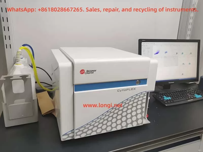
The Cydem VT system is a modular, fully automated cell culture platform that integrates four core modules: temperature control, gas regulation, liquid handling, and real-time monitoring. Designed to replace traditional manual operations, it is suitable for scenarios requiring high repeatability and sterile conditions, such as pharmaceutical research and development, oncology research, and stem cell culture. The system enables human-machine interaction through a touchscreen interface and remote control software, supporting multi-task parallel processing.
1.2 Technical Features Analysis
- Precise Environmental Control: The incubator maintains a temperature fluctuation range of ≤ ±0.2°C, CO₂ concentration control accuracy of ±0.1%, and humidity above 95%, ensuring a stable environment for cell growth.
- Automated Liquid Handling: Equipped with a built-in multi-channel pipetting arm, it supports liquid transfer from 1 μL to 50 mL with an error rate below 2%.
- Contamination Prevention Mechanism: It employs a dual safeguard of HEPA filtration and UV sterilization, with key pipelines equipped with check valves to prevent cross-contamination.
- Data Traceability Function: All operational parameters and cell images are automatically stored and can be exported in CSV or PDF formats.
Chapter 2: Hardware Installation and Initial Configuration
2.1 Site Preparation Requirements
The system should be placed on a level and stable laboratory bench with a surrounding clearance of at least 50 cm for heat dissipation. The power supply requirement is 220 V ± 10%/50 Hz, and an independent grounding line must be connected. The ambient temperature is recommended to be maintained between 18°C and 25°C, avoiding direct sunlight or direct alignment with ventilation openings.
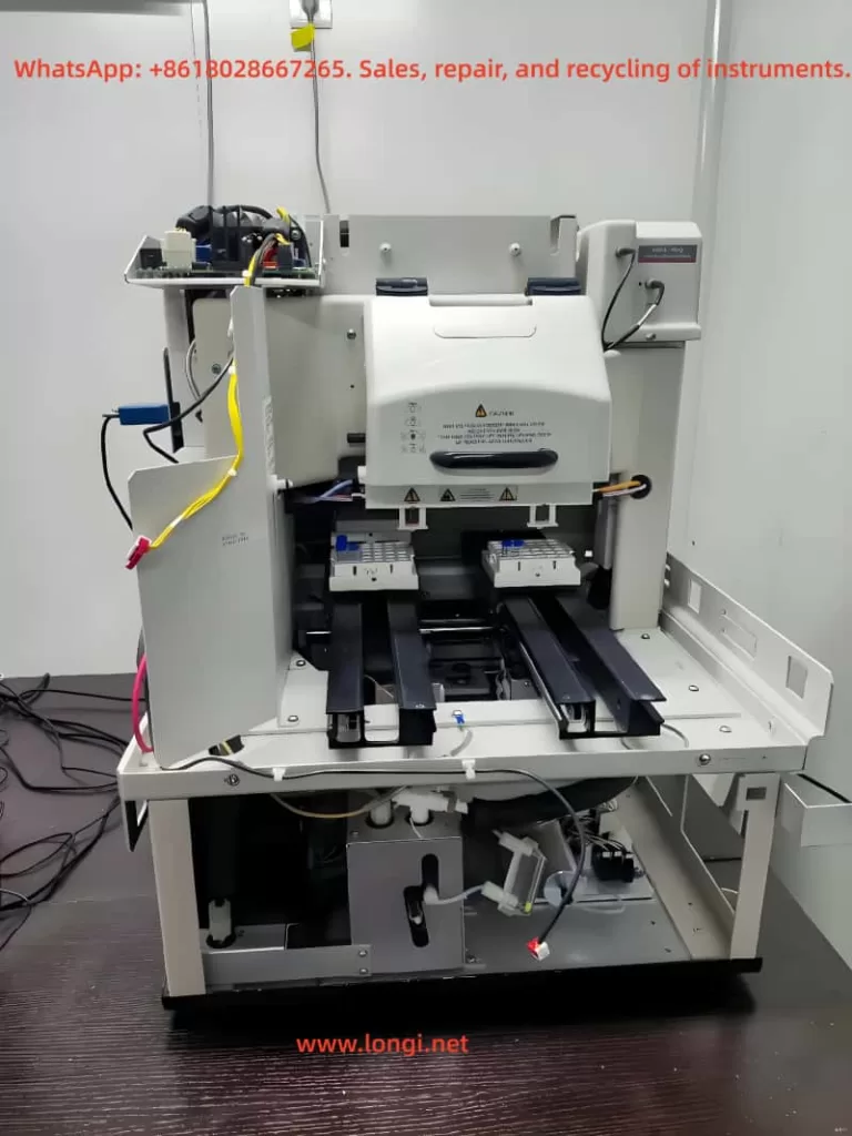
2.2 Core Component Installation Process
- Main Unit Positioning: Remove the transportation fixing bolts and adjust the feet until the level indicator shows green.
- Culture Module Assembly: Insert the culture dish holder into the slide rail until it locks into place with a click. Handle glass components gently.
- Liquid Pathway Connection:
- Connect the culture medium bottle and waste liquid bottle to the color-coded interfaces respectively (blue for air intake, red for liquid pathway).
- Perform pipeline priming: Select “Liquid Pathway Cleaning” in the software interface until there are no air bubbles in the pipeline.
- Gas Source Configuration: Connect the CO₂ cylinder to the back interface of the system through a pressure reducer, with an initial pressure setting recommended at 0.1–0.15 MPa.
2.3 First-time Startup and Calibration
After powering on, the system performs a self-check (approximately 5 minutes), and the touchscreen displays the initialization interface. Follow the prompts to complete:
- Sensor Calibration: Including pH electrode calibration (using standard buffer solutions) and O₂ probe calibration (zeroing in air).
- Mechanical Arm Origin Correction: The pipetting arm automatically moves to the preset position and records the coordinates.
- User Permission Settings: Assign administrator and operator accounts, set passwords, and define operational scope restrictions.
Chapter 3: Full Process Analysis of Daily Operations
3.1 Culture Initiation Phase
- Step 1 – Program Creation: Create a new task in the “Protocol Editor,” with key parameters including:
- Culture type (adherent/suspension cells)
- Liquid exchange frequency (e.g., every 48 hours)
- Termination conditions (OD value ≥ 0.8 or time threshold)
- Step 2 – Sample Loading:
- Use sterile forceps to place the culture dish on the loading platform and scan the barcode to associate sample information.
- For adherent cells, allow them to settle for 10 minutes; for suspension cells, directly initiate the mixing program.
- Step 3 – Environmental Parameter Setting: Select a preset mode according to the cell type (e.g., the HEK-293 mode automatically sets to 37°C/5% CO₂), or manually input:
Temperature: 37.0°C
CO₂: 5.0%
O₂: Set as required (conventionally 20%)
Humidity: ≥ 95%
3.2 Monitoring During Operation
- Real-time Data Viewing: Switch to the “Monitoring” tab on the main interface to view temperature fluctuation curves and pH trend graphs.
- Abnormal Alarm Handling: When a “Liquid Insufficient” warning appears, pause the task → replace the culture medium bottle → resume operation.
- Intermediate Intervention Operations: Wear sterile gloves, pause the mechanical arm using the emergency stop button, and quickly complete sampling or liquid supplementation.
3.3 Culture Termination and Sample Collection
Select the target experiment from the task list and click “Terminate.” The system automatically performs:
- The pipetting arm aspirates and discards the waste liquid.
- It injects 0.25% trypsin (for adherent cells).
- The low-temperature preservation module is lowered to 4°C.
After removing the samples, immediately execute the “Quick Clean” program (taking approximately 15 minutes).
Chapter 4: Maintenance and Upkeep Specifications
4.1 Daily Maintenance Checklist
- Check the waste liquid bottle level (empty if it exceeds 80%).
- Wipe the touchscreen and exterior surfaces with 70% ethanol.
- Confirm the remaining pressure in the CO₂ cylinder (replace if it is below 0.05 MPa).
4.2 Weekly In-depth Maintenance
- Pipeline Disinfection: Run the “Sterilization” program and circulate 0.1 M NaOH solution for 30 minutes.
- Mechanical Arm Lubrication: Apply specialized silicone grease to the XYZ-axis guide rails (never use Vaseline).
- Sensor Calibration: Soak the pH electrode in 3 M KCl storage solution and perform air calibration for the O₂ sensor.
4.3 Monthly Inspection Items
- Replace the HEPA filter (Part Number: CYD-FIL-01).
- Check the aging of the sealing rings of the pipette tips.
- Back up system logs and user data to an external storage device.
Chapter 5: Fault Diagnosis and Emergency Response
5.1 Common Alarm Handling Solutions
| Alarm Code | Meaning | Handling Action |
|---|---|---|
| E-102 | Temperature Exceeding Limit | Check the incubator door seal and reset the heating module. |
| E-205 | Liquid Pathway Blockage | Execute the pipeline backflush program and replace the 0.22 μm filter. |
| E-311 | Communication Timeout | Restart the control computer and check the network cable connection. |
5.2 Emergency Situation Response
- Power Interruption: The system automatically activates the backup battery to maintain the operation of key sensors. Power must be restored within 2 hours.
- Contamination Incident: Immediately initiate “Emergency Sterilization” (UV + 75% ethanol spray). Contaminated culture dishes must be autoclaved before disposal.
- Mechanical Arm Collision: Enter “Maintenance Mode” to manually adjust the arm position and calibrate the track encoder.
Chapter 6: Advanced Functions and Application Expansion
6.1 Multi-task Parallel Strategy
Through the “Batch Scheduler” function, up to 6 independent experiments can be managed simultaneously. It is recommended to group them according to the following principles:
- Arrange the same type of cells in the same batch.
- Prioritize high-frequency detection tasks for daytime periods.
- Set resource conflict warnings (e.g., detection of overlapping pipette usage).
6.2 Data In-depth Analysis Techniques
- Growth Curve Fitting: After exporting OD data, use the built-in Gompertz model in the system to calculate the doubling time.
- Morphological Analysis: Combine with the microscopic imaging module to quantify cell aggregation degree through image segmentation algorithms.
- Custom Report Template: In the “Report Generator,” drag and drop fields to generate experimental reports compliant with GLP specifications.
6.3 Remote Control Configuration
After connecting to the laboratory local area network via Ethernet:
- Enable “Remote Access” permissions in the administrator account.
- Use the official app (Cydem Controller) to scan the device QR code for binding.
- Set operation delay compensation (recommended ≤ 200 ms within the local area network).
Conclusion
The value of the Cydem VT system lies not only in replacing manual operations with automation but also in ensuring the repeatability and traceability of experimental data through standardized processes. It is recommended that users establish a complete set of SOP documentation, participate in technical training organized by the manufacturer at least once a year, and stay updated on firmware update announcements to obtain functional optimizations. This guide covers the core operational scenarios of the system, and parameters should be flexibly adjusted according to specific experimental needs in actual use to maximize equipment performance.