
Introduction
In modern industrial drive systems, a Variable Frequency Drive (VFD) is not merely a device for motor speed control; it also serves as a central node for signal exchange, system protection, and process optimization. Among the wide range of VFDs available, the Vacon NXP series (now part of Danfoss Drives) is recognized for its modular design, high performance, and adaptability across heavy-duty applications such as pumps, fans, compressors, conveyors, and marine propulsion.
However, despite its robustness, engineers often encounter specific fault codes related to device recognition, most notably F38 (Device Added) and F40 (Device Unknown). These alarms typically arise from issues with option boards, particularly the I/O extension boards (OPT-A1 / OPT-A2), which play a crucial role in extending the input and output capacity of the drive.
This article presents an in-depth technical analysis of these faults, explains their root causes, outlines systematic troubleshooting methods, and provides best practices for handling input option boards in Vacon NXP drives.
1. Modular Architecture of Vacon NXP Drives
1.1 Control and Power Units
The NXP drive family is built on a modular architecture:
- Power Unit (PU): Performs the AC–DC–AC conversion, consisting of rectifiers, DC bus, and IGBT inverter stage.
- Control Unit (CU): Handles PWM logic, motor control algorithms, protective functions, and overall coordination.
Communication between the control unit and the power unit is essential. If the CU cannot properly identify the PU, the drive triggers F40 Device Unknown, Subcode S4 (Control board cannot recognize power board).
1.2 Option Boards
To extend the standard functionality, Vacon NXP supports a variety of option boards:
- OPT-A series: Basic input/output expansion (digital/analog I/O).
- OPT-B series: Specialized I/O or measurement inputs (temperature, additional analog channels).
- OPT-C/OPT-D series: Communication boards (Profibus, Modbus, CANopen, EtherCAT, etc.).
At power-up, the drive scans all inserted option boards. A new detection event will cause F38 Device Added, while a failed recognition will raise F40 Device Unknown.
2. Meaning of F38 and F40 Faults
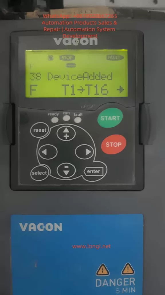
2.1 F38 Device Added
This alarm indicates that the drive has detected the presence of a new option board.
It may be triggered when:
- A new board is inserted after power-down.
- An existing board has been reseated or replaced.
- Faulty hardware causes the system to misinterpret the card as newly added.
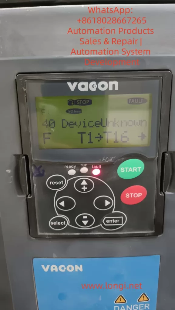
2.2 F40 Device Unknown
This alarm indicates that the drive recognizes the presence of a board but cannot identify it correctly.
Typical subcodes include:
- S1: Unknown device.
- S2: Power unit type mismatch.
- S4: Control board cannot recognize the power board.
In real-world cases, F40 combined with S4 strongly suggests a mismatch or communication failure between the control unit and an option board or power board.

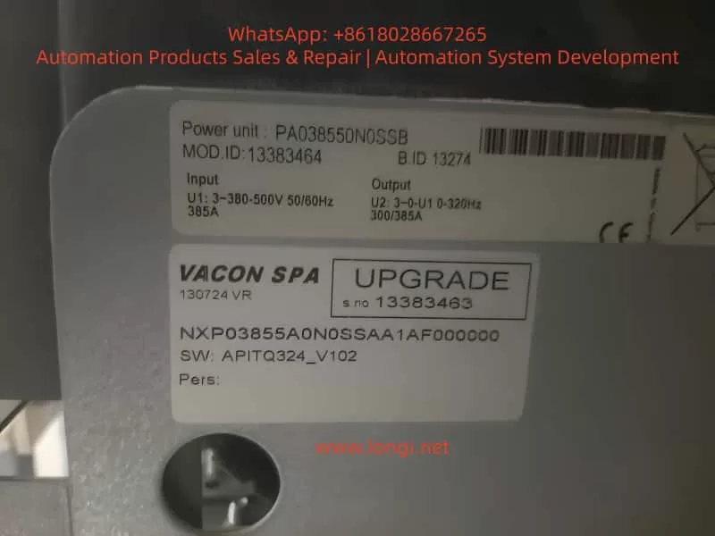
3. Case Study: Iranian Customer Drive
A real field case involved a Vacon NXP drive model NXPO3855A0N0SSAA1AF000000, rated for 3×380–500V, 385A. The customer reported the following sequence of issues:
- The drive raised F40 Device Unknown during operation.
- After resetting and further testing, F38 Device Added appeared.
- Removing a particular I/O option board eliminated the fault, and the drive operated normally.
- Reinserting the same board or attempting with an incompatible new board caused the fault to reappear.
- Investigation revealed that the input board had previously suffered a short circuit, leading to control board shutdown.
This case confirmed that the root cause of the alarm was linked directly to the damaged input option board.
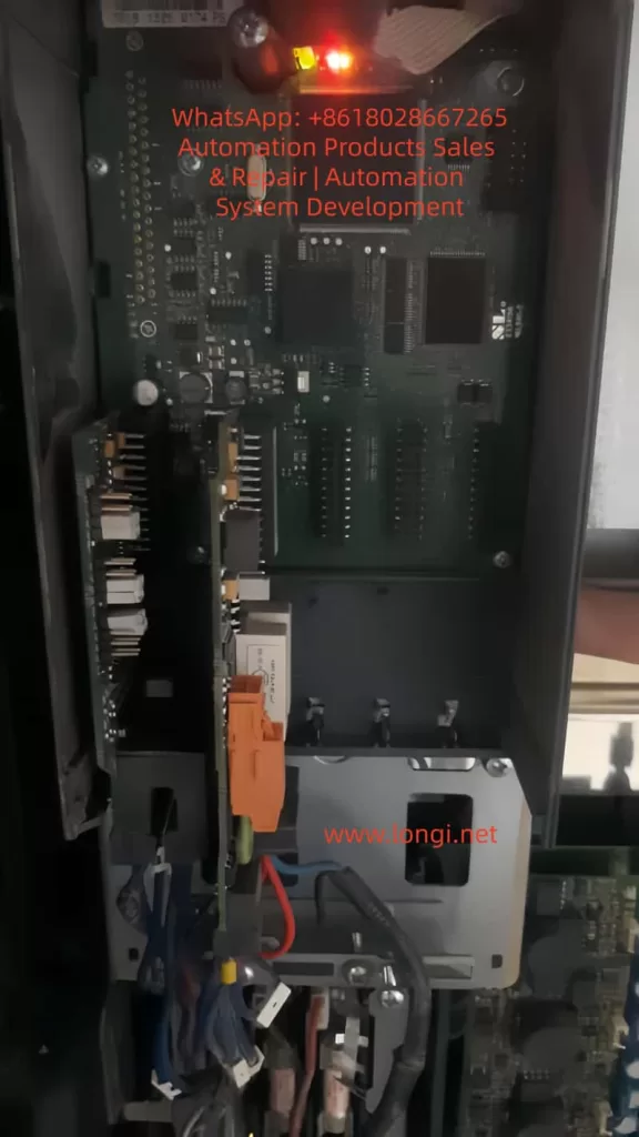
4. I/O Option Boards and Their Roles
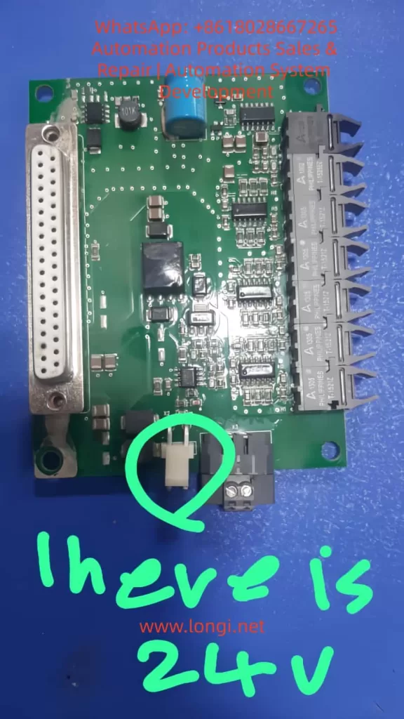
4.1 OPT-A1 Standard I/O Board
- Provides multiple digital inputs, digital outputs, analog inputs, and analog outputs.
- Includes a DB-37 connector for external I/O expansion.
- Contains configuration jumpers (X1, X2, X3, X6) to select between current/voltage modes for analog channels.
- Widely used in process applications where the drive must interface with external control systems.
4.2 OPT-A2 Relay Output Board
- Provides two relay outputs.
- Switching capacity: 8 A @ 250 VAC or 24 VDC.
- Simple functionality, typically used for alarms, run status signals, or external contactor control.
4.3 Identifying the Correct Board
To determine which option board is required:
- Check the silkscreen or label on the PCB (e.g., “OPT-A1”).
- Verify the drive’s delivery code, which often specifies included option boards.
- Compare board layouts with manual illustrations (I/O terminals, connectors).
In the discussed case, the faulty card matched the structure of an OPT-A series board, most likely OPT-A1, given its combination of DB-37 connector and relay components.
5. Common Failure Mechanisms of Option Boards
5.1 Short Circuit
Causes: incorrect wiring, external equipment failure, conductive dust, or moisture.
Effects:
- The drive’s 24 V auxiliary supply collapses.
- Communication lines between the option board and control board are pulled low, preventing recognition.
5.2 Component Failure
- Input protection resistors and capacitors can burn out.
- Opto-isolators may short.
- Relay coils or driver ICs may fail under overcurrent.
5.3 Control Board Interface Damage
Severe shorts may propagate into the control board backplane, damaging bus transceivers or I/O interfaces. Even with a new option board installed, recognition may still fail.
6. Troubleshooting and Repair Workflow
6.1 Initial Verification
- Record all fault codes, subcodes (S4), and T-parameters (T1–T16).
- Remove the suspected option board → does the fault clear?
- Insert another board → does the fault repeat?
6.2 Physical Inspection
- Check the board for burn marks or cracked components.
- Measure the 24 V auxiliary supply.
- Inspect connector pins for oxidation or melting.
6.3 Replacement Testing
- Replace the damaged board with an identical model.
- Do not substitute with a different board type (e.g., OPT-A2 instead of OPT-A1). This results in F38 alarms.
- If faults persist with the correct new board, control board interface damage must be suspected.
6.4 Control Board Diagnostics
- Verify communication between the control board and the option slot (bus signals, isolation).
- Confirm compatibility with the power unit.
- If the interface is damaged, replacement or board-level repair of the control board is required.
7. Importance of Firmware and Parameter Compatibility
The ability of the drive to recognize option boards depends on firmware support:
- Old firmware may not recognize new board revisions.
- When replacing either control or power units, firmware compatibility must be confirmed.
- Certain parameters must be configured to enable board functions; otherwise, the board may remain inactive even if detected.
Firmware upgrades and parameter resets are therefore integral steps during option board replacement.
8. Preventive Measures and Maintenance Practices
- Correct Spare Part Management
- Always procure the exact option board model specified by the drive’s configuration.
- Maintain a record of which boards are installed in each drive.
- Avoid Hot-Swapping
- Option boards must be inserted and removed only when the drive is powered down.
- Hot-swapping risks damaging both the board and the control unit.
- Wiring Standards
- Ensure input signals comply with voltage/current specifications.
- Use isolators or protection circuits for noisy or high-energy signals.
- Environmental Protection
- Keep enclosures clean and dry.
- Protect against conductive dust, humidity, and vibration.
- Failure Logging
- Record all occurrences of F38/F40 alarms with timestamps and parameters.
- Analyze trends to improve maintenance and prevent recurrence.
9. Conclusion
The F38 Device Added and F40 Device Unknown faults in Vacon NXP drives are primarily related to option board recognition issues. When an input option board suffers from a short circuit, the drive either misinterprets it as a new device (F38) or fails to identify it (F40).
The presented case study highlights that:
- Removing the faulty card clears the fault, proving that the main drive remains functional.
- Replacing the board with a non-identical model reintroduces the fault.
- The correct solution is to replace the damaged option board with an identical OPT-A1/OPT-A2 board and verify that the control board interface is intact.
By understanding the modular architecture of the Vacon NXP, following systematic troubleshooting steps, and applying preventive maintenance practices, field engineers can quickly resolve such device recognition issues and ensure reliable long-term drive operation.