
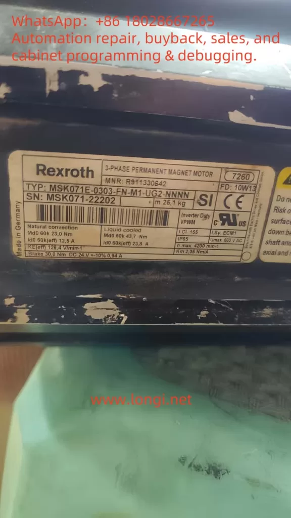
1. Confirm Motor Model and Brake Parameters
- Model: MSK071E-0303-FN-M1-UG2-NNNN
- Nameplate Parameters: Brake 30Ω, DC 24V ±10%, 0.94A
👉 Indicates that this motor is equipped with a DC brake, rated for a working voltage of 24VDC, which releases the brake when powered and locks it when de-energized.
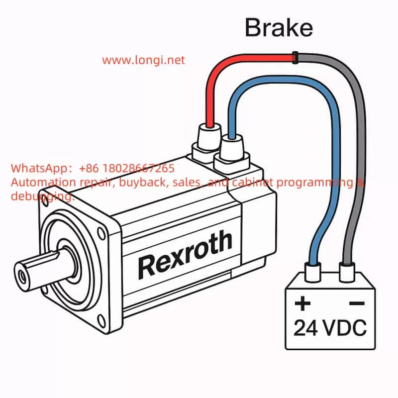
2. Wiring Identification
- Red Wire → +24VDC
- Blue Wire → 0V (Negative)
- (Gray Wire Pair) = Temperature Sensor, not involved in brake testing.
3. Power Supply Preparation
- Use a regulated 24VDC power supply with a rated current of ≥2A (reserve a margin, although normal operation requires approximately 1A).
- The power supply should have overcurrent protection to prevent damage from short circuits.
- If possible, it is best to use a power supply with soft start or current limiting functions.
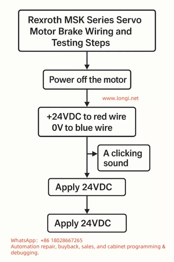
4. Testing Steps
- Disconnect the motor and confirm that the motor’s main power supply is not connected.
- Connect the positive terminal of the power supply to the red wire and the negative terminal to the blue wire.
- Apply 24VDC power:
- You should hear a “click” sound, indicating that the brake has been released.
- Gently rotate the motor shaft by hand; it should rotate freely.
- Disconnect the 24VDC power supply:
- Attempt to rotate the motor shaft again; it should be locked by the mechanical brake.
5. Precautions
- Never operate the motor shaft for extended periods with the brake continuously powered without control from a motor driver, as excessive inertia from shaft rotation may damage the brake pads.
- In practical applications with a driver, the brake signal is usually controlled by the driver’s Brake Output; do not continuously apply direct power.
- If the brake fails to release, check the following:
- Whether the power supply voltage is within 24V ±10%.
- Whether the power supply current is sufficient.
- Whether the red/blue wires are reversed (reversing them will prevent release).
✅ Summary:
- Red → +24VDC, Blue → 0V
- Power on to release, power off to lock.
- Testing method: Listen for sound, rotate shaft.