
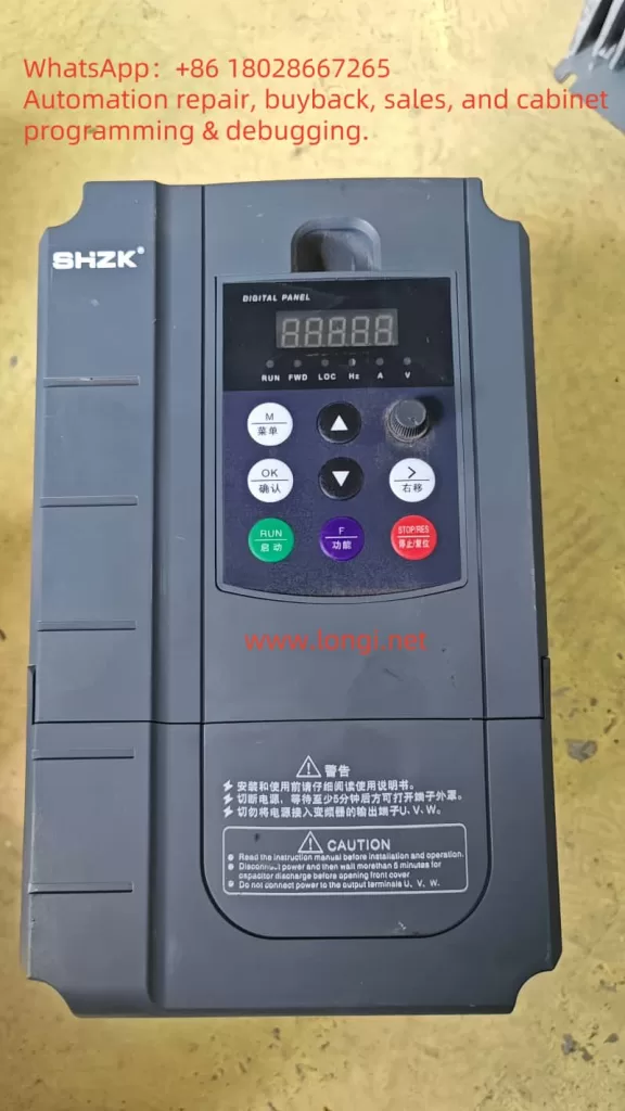
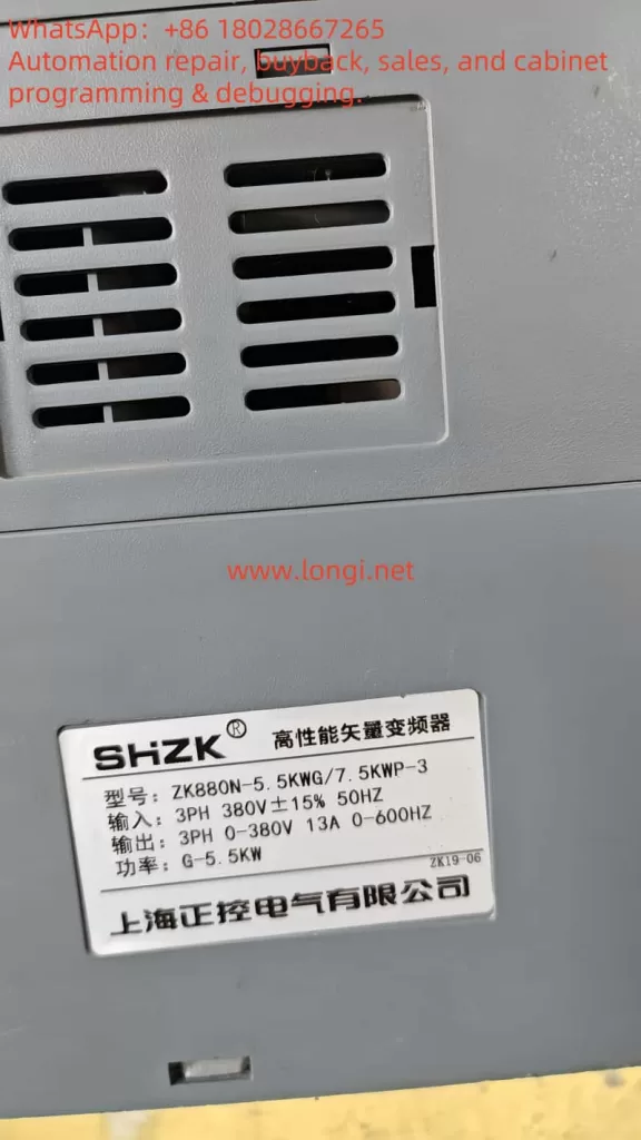
In the field of industrial automation control, inverters, as the core equipment for motor speed regulation, are widely used in various scenarios requiring graded speed regulation, such as fans, pumps, and conveyor belts. This article will take the ZK880-N positive control inverter as an example, combined with official technical documentation and practical application scenarios, to elaborate in detail on how to achieve three-stage speed control through DI digital input terminals, providing systematic guidance from hardware wiring to parameter settings.
I. Technical Principles of Three-Stage Speed Control
The essence of three-stage speed control is to preset the motor operating frequency into three different levels through the multi-stage speed instruction function of the inverter. Users can select the corresponding frequency band through external switch signals to realize the graded regulation of motor speed. The ZK880-N inverter uses digital input terminals (DI) as the trigger signal source, combined with function code parameter settings, to build a flexible and reliable multi-stage speed control system.
II. Hardware Wiring Implementation Steps
1. Terminal Function Definition
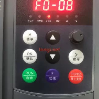
According to control requirements, the DI1-DI3 digital input terminals need to be configured as multi-stage speed control ports. Refer to the inverter terminal distribution diagram, with standard wiring terminals located in the control circuit interface area.
2. Wiring Specifications
- Power Connection: Ensure that the main circuit power supply (R/S/T) and control circuit power supply (usually +24V) of the inverter are correctly connected.
- DI Terminal Wiring:
- DI1: As the first-stage speed trigger terminal, it is recommended to connect a normally open contact switch.
- DI2: As the second-stage speed trigger terminal.
- DI3: As the third-stage speed trigger terminal.
- Common Terminal (COM): The signal common terminal for all DI terminals, which should be connected to the other end of the switch.
3. Wiring Precautions
- The switch signal voltage range must comply with the DI terminal input specifications (5-30V DC).
- It is recommended to use shielded twisted pair cables for signal transmission to avoid electromagnetic interference.
- After wiring, use a multimeter to detect the insulation resistance between terminals to ensure there is no short circuit.
III. Detailed Explanation of Core Parameter Settings
The following function codes need to be configured through the operation panel or dedicated software:
1. DI Terminal Function Mapping
| Function Code | Parameter Item | Setting Value | Function Description |
|---|---|---|---|
| F4-00 | DI1 Function Selection | 4 | Multi-stage Speed 1 (corresponding to the first-stage speed) |
| F4-01 | DI2 Function Selection | 5 | Multi-stage Speed 2 (corresponding to the second-stage speed) |
| F4-02 | DI3 Function Selection | 6 | Multi-stage Speed 3 (corresponding to the third-stage speed) |
2. Multi-Stage Speed Frequency Settings
| Function Code | Parameter Item | Setting Value | Typical Application Scenarios |
|---|---|---|---|
| FC-00 | Multi-stage Speed 1 Frequency | 20Hz | Light load start/low-speed operation |
| FC-01 | Multi-stage Speed 2 Frequency | 35Hz | Normal working speed |
| FC-02 | Multi-stage Speed 3 Frequency | 50Hz | High-speed discharge/emergency acceleration |
3. Operating Parameter Configuration
| Function Code | Parameter Item | Recommended Value | Function Description |
|---|---|---|---|
| F6-00 | Acceleration Time 1 | 8.0s | Transition time from first-stage to second-stage speed |
| F6-01 | Deceleration Time 1 | 5.0s | Transition time from second-stage to first-stage speed |
| F6-02 | Acceleration Time 2 | 12.0s | Transition time from second-stage to third-stage speed |
| F6-03 | Deceleration Time 2 | 8.0s | Transition time from third-stage to second-stage speed |
| FC-16 | Operation Instruction Selection | 1 | Terminal control mode |
| FC-17 | Fault Reset Selection | 1 | Allow DI terminals to perform fault reset |
IV. Realization of Three-Stage Speed Control Logic
1. Single Terminal Single-Stage Speed Mode
- Only DI1 is closed: The motor operates at the frequency set by FC-00 (20Hz).
- Only DI2 is closed: The motor operates at the frequency set by FC-01 (35Hz).
- Only DI3 is closed: The motor operates at the frequency set by FC-02 (50Hz).
2. Combined Control Mode (Advanced Application)
Through function codes FC-03 to FC-07, combined stage speeds can be set:
- DI1+DI2 closed: Execute the frequency set by FC-03 (reserved for extended stage speed).
- DI2+DI3 closed: Execute the frequency set by FC-04 (reserved for extended stage speed).
- Special application scenarios: Realize automatic stage speed switching logic through PLC programming.
V. Commissioning and Verification Process
1. No-Load Test Stage
- Disconnect the motor load and only retain the inverter and dummy load.
- Close the DI1-DI3 switches in turn to observe whether the output frequency is consistent with the set value.
- Use an oscilloscope to detect the output voltage waveform and confirm there is no distortion.
2. Load Commissioning Stage
- Gradually load to the rated load.
- Test the current impact during stage speed switching (should be less than 1.5 times the rated current).
- Verify whether the acceleration/deceleration time meets the process requirements.
3. Abnormal Handling Test
- Simulate DI terminal signal adhesion fault.
- Verify the effectiveness of the FC-17 fault reset function.
- Test the reliability of overload protection (OL) action.
VI. Typical Application Cases
In a certain water plant’s constant pressure water supply system, the three-stage speed control of the ZK880-N inverter is adopted:
- First-stage speed (25Hz): Maintain the basic pressure of the pipe network during night low-peak periods.
- Second-stage speed (40Hz): Meet normal water demand during daytime water supply.
- Third-stage speed (50Hz): Quickly supplement the pipe network pressure during peak water consumption periods.
Through the automatic switching of stage speeds by pressure sensor signals, an energy-saving rate of 32% is achieved, and the pressure fluctuation range is controlled within ±0.02MPa.
VII. Maintenance and Optimization Suggestions
- Regularly check the reliability of DI terminal wiring, and recommend tightening every six months.
- Recheck the FC-00 to FC-02 parameter settings every quarter according to load characteristics.
- Upgrade to the latest firmware version (currently V2.13) to obtain an optimized stage speed switching algorithm.
- For impact loads, it is recommended to add an input reactor to improve power quality.
By following the above systematic implementation steps, users can efficiently achieve the three-stage speed control function of the ZK880-N inverter. In practical applications, it is necessary to combine specific process requirements and optimize parameters to achieve the best control effect. With the development of Industry 4.0, this inverter supports the Modbus-RTU communication protocol and can be integrated with the host computer system to achieve more intelligent stage speed scheduling management.