Introduction
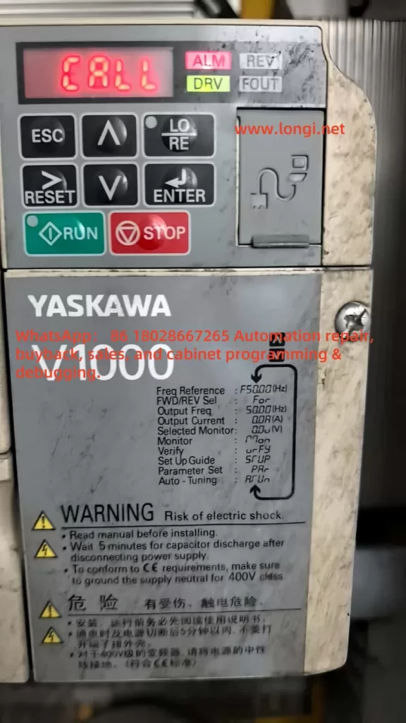
The Yaskawa V1000 series inverter is renowned for its efficient vector control performance and wide range of applications, making it a vital component in industrial automation, including systems like fans, pumps, and conveyor belts. However, during operation, the inverter may encounter various faults, with the “CALL” fault being a common communication-related issue. When the inverter’s display shows “CALL” accompanied by the ALM (alarm) light turning on, it typically indicates a communication link abnormality, which may result in system shutdown. This article provides an in-depth analysis of the nature of the “CALL” fault, its causes, and resolution methods, along with preventive measures to help users quickly restore equipment operation and enhance system reliability.

Nature of the “CALL” Fault
In the Yaskawa V1000 series inverter, “CALL” generally signifies a communication-related issue, potentially indicating that the inverter is awaiting a signal from a master device (e.g., PLC) or has detected an error in the communication link. In some instances, “CALL” may serve as a general prompt, urging users to investigate specific fault codes (e.g., “CE” for MEMOBUS/Modbus communication errors) further. The illumination of the ALM light suggests the inverter has detected an abnormal state, typically interrupting output and allowing the motor to enter a free-stop mode.
Based on relevant documentation, while “CALL” is not explicitly listed in the V1000 series fault code table, it is closely related to communication problems, possibly linked to codes like “CE” (MEMOBUS/Modbus communication error) or “bUS” (option card communication error). In certain communication protocols (e.g., Modbus), “CALL” might indicate a more severe communication issue, potentially necessitating inverter replacement.
Causes of the “CALL” Fault
The occurrence of a “CALL” fault may be attributed to the following causes:
- Communication Cable Wiring Issues:
- Loose, broken, or short-circuited communication cables can lead to data transmission failure.
- Incorrect wiring (e.g., improper terminal connections) may prevent communication between the inverter and the master device.
- Communication Parameter Configuration Errors:
- Mismatched communication parameters (e.g., HS-01 slave address, HS-02 communication speed, HS-03 parity) with the master device.
- For example, if the inverter’s baud rate is set to 9600 bps while the PLC is set to 19200 bps, communication will not establish.
- Hardware Problems:
- Failure or improper installation of communication option cards (e.g., Modbus, CC-Link, or PROFIBUS-DP cards).
- Damaged or poorly contacted communication terminals.
- Electromagnetic Interference (EMI):
- Common electromagnetic noise in industrial environments (e.g., from motors or transformers) may disrupt communication signals, causing data transmission errors.
- Master Station Program Errors:
- Incorrect configuration in the master device (e.g., PLC) may prevent proper command transmission or response reception.
- For instance, the PLC may not have the correct slave address or communication protocol set.
- Communication Timeout:
- If the inverter does not receive a response from the master within a specified time (e.g., as set by parameter HS-09), it may trigger a “CALL” fault.
Steps to Resolve the “CALL” Fault
To effectively address a “CALL” fault, follow these troubleshooting and resolution steps:

Step 1: Inspect Physical Connections and Wiring
- Check Cables: Inspect communication cables for damage, breaks, or short circuits. Ensure the correct cable type (e.g., RS-485 or RS-422) is used.
- Verify Connections: Confirm all terminals are securely connected with no looseness or poor contact.
- Refer to Manual: Ensure terminal connections (e.g., R+, R-, S+, S-) are correct as per the Yaskawa V1000 technical manual.
Step 2: Verify Communication Parameters
- Use the inverter’s digital operator panel or programming software (e.g., DriveWorksEZ) to check the following parameters:
- HS-01 (Slave Address): Set to a unique address between 1-247, matching the master device.
- HS-02 (Communication Speed): Confirm baud rate (e.g., 9600, 19200 bps) matches the master.
- HS-03 (Parity): Select the appropriate parity setting (none, odd, even).
- HS-04 (Fault Action Selection): Define the action upon communication failure (e.g., decelerate to stop or free stop).
- HS-09 (Timeout Time): Adjust timeout to suit system needs.
- Save changes and retest communication.
Step 3: Perform Self-Diagnostic Test
- Per the technical manual, set parameter H1-06 to 67 to enter communication test mode.
- Power off, connect test terminals, power on again, and check if the display shows “PASS” (normal) or “CE” (fault).
- This test helps identify issues with the communication line or hardware.
Step 4: Adjust Terminal Resistor Settings
- For RS-485 networks, ensure terminal resistors are correctly set (typically “ON”).
- Check terminal resistor configuration per the technical manual.
Step 5: Reduce Electromagnetic Interference
- Check for EMI sources (e.g., motors, transformers) in the vicinity.
- Use shielded cables and ensure proper grounding.
- Install EMI filters or surge suppressors as recommended.
Step 6: Inspect Master Device
- Verify the PLC or other master device’s communication settings and program are correct.
- Ensure commands sent by the master match the inverter’s communication protocol and parameters.
Step 7: Consult Technical Support
- If issues persist, refer to the Yaskawa V1000 technical manual’s troubleshooting section.
- Contact Yaskawa support with details including model number, software version, purchase date, and fault description.
Note: In Modbus communication, if “CALL” persists, it may indicate a severe fault, potentially requiring inverter replacement as a last resort.
Preventive Measures
To reduce the likelihood of “CALL” faults, consider the following preventive actions:
- Regular Maintenance of Communication Lines:
- Periodically inspect cables and terminals for damage or looseness.
- Promptly replace aged or damaged cables.
- Record Communication Parameters:
- Document all communication settings (e.g., slave address, baud rate) for quick verification and adjustment.
- Update records after system changes or modifications.
- Use EMI Protection Measures:
- Employ shielded cables and ensure proper grounding.
- Install EMI filters or surge suppressors to reduce noise impact.
- Keep Firmware Updated:
- Regularly check for firmware updates.
- Update firmware to address known communication issues.
- Routine System Checks:
- Conduct regular inspections of the inverter, master device, and communication network to identify potential issues early.
- Train Operating Personnel:
- Train operators and maintenance staff on inverter operation, fault codes, and troubleshooting procedures.
- Ensure personnel can correctly interpret “CALL” and other fault messages and take appropriate action.
Fault Code Reference Table
Below are common communication-related fault codes for the V1000 series inverters and their descriptions:
| Fault Code | Description | Possible Causes | Resolution Methods |
|---|---|---|---|
| CE | MEMOBUS/Modbus Communication Error | No response from master, parameter mismatch, wiring issues | Check parameters, wiring, perform self-diagnostic test |
| bUS | Option Card Communication Error | Option card failure, wiring issues, incorrect terminal resistor | Check option card, wiring, adjust terminal resistor |
| CALL | Communication Wait or Error | Awaiting communication signal, wiring/parameter issues, hardware failure | Check wiring, parameters, perform self-diagnostic, consider replacement |
Conclusion
The “CALL” fault is a significant communication-related issue in Yaskawa V1000 series inverters, potentially leading to system downtime and affecting production efficiency. By inspecting wiring, verifying communication parameters, performing self-diagnostic tests, and reducing electromagnetic interference, most “CALL” faults can be resolved. Implementing preventive measures such as regular maintenance, parameter documentation, and the use of shielded cables can greatly reduce the incidence of such faults. For complex or persistent issues, consulting the Yaskawa V1000 technical manual or contacting Yaskawa technical support for professional assistance is recommended. Ensuring the reliability of the communication system is crucial for maintaining stable operation in industrial applications.
