
Understanding and Resolving the Err20 Fault (Module Overcurrent) in Baojie Servo AG Series
The Baojie Servo AG Series is a widely utilized industrial servo drive system known for its robust performance and advanced control features. However, like any sophisticated machinery, it is susceptible to operational faults, one of which is the “Err20” fault code displayed on the control panel. This error, accompanied by the indication of “module overcurrent,” signals a critical issue that requires immediate attention to prevent damage to the equipment and ensure uninterrupted production. This article delves into the nature of the Err20 fault, its potential causes, diagnostic procedures, and effective resolution strategies, drawing from the technical insights provided in the AG Series user manual.
What is the Err20 Fault?
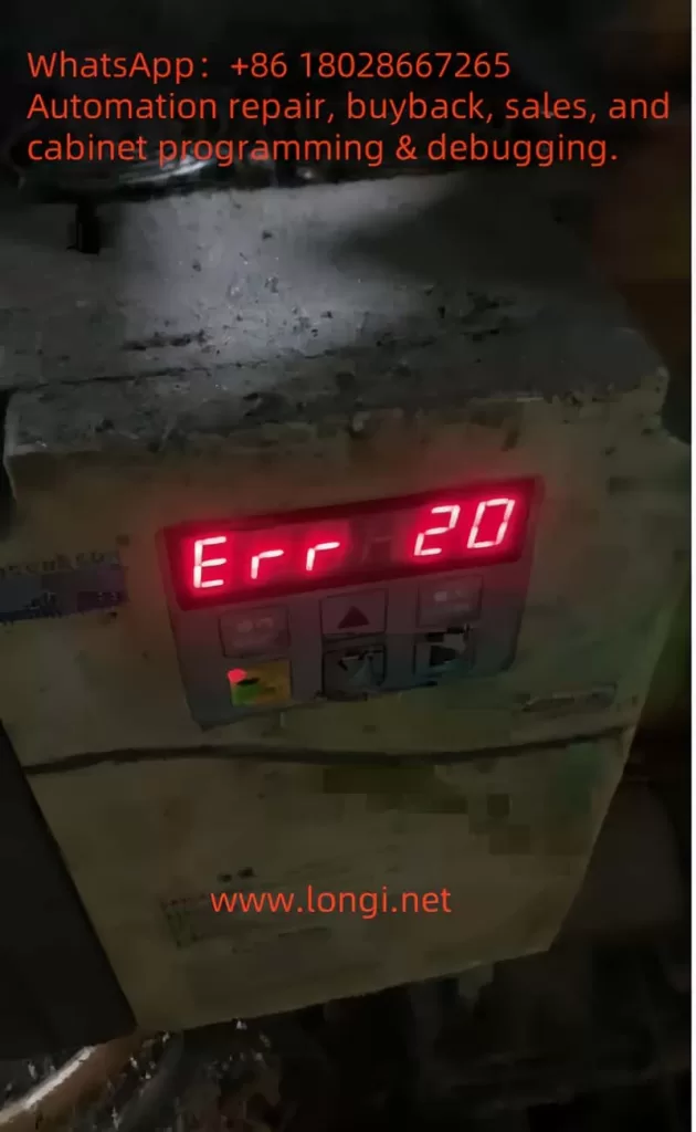
The Err20 fault code on the Baojie Servo AG Series control panel indicates a module overcurrent condition. Overcurrent occurs when the electrical current flowing through the servo drive’s power module exceeds its rated capacity. This can lead to overheating, potential damage to the internal components, or even a complete system shutdown to protect the hardware. The user manual highlights that such faults are part of the system’s safety diagnostics, designed to alert operators to issues that could compromise the drive’s integrity or the machinery it controls.
The display of “Err20” alongside a numerical value (e.g., 20) suggests a specific error category within the fault diagnostic framework outlined in Chapter 8 of the manual, “Fault Diagnosis Explanation.” This chapter emphasizes the importance of understanding alarm codes to identify and rectify underlying issues promptly.
Potential Causes of the Err20 Fault
Several factors can trigger the Err20 fault in the Baojie Servo AG Series. Understanding these causes is the first step toward effective troubleshooting:
- Overload Conditions: Excessive mechanical load on the servo motor, beyond its specified capacity, can cause the current to spike, triggering the overcurrent protection. This might occur due to jammed machinery or an improperly calibrated load.
- Short Circuits: An unintended electrical connection between the drive’s output terminals (e.g., U, V, W) or within the motor wiring can result in a short circuit, leading to a sudden surge in current.
- Faulty Wiring or Connections: Loose, damaged, or incorrectly installed wiring can disrupt normal current flow, potentially causing overcurrent conditions. The manual’s Chapter 3, “Installation and Debugging,” stresses the importance of secure and correct wiring practices.
- Component Wear or Failure: Over time, components such as the power module, capacitors, or transistors may degrade, especially if maintenance schedules (detailed in Chapter 9, “Maintenance and Care”) are not followed. A failing component can lead to irregular current draw.
- Improper Parameter Settings: Incorrect settings in the drive’s internal parameters, such as those adjustable via the operation panel (Chapter 5, “Parameter Setting Explanation”), can misconfigure the current limits, inadvertently allowing overcurrent situations.
- Environmental Factors: Operating the drive in harsh conditions—high temperatures, dust, or humidity—can affect its performance. The manual recommends regular cleaning (e.g., Section 9.4 for 7.5-11kW drive cleaning methods) to mitigate such risks.
Diagnostic Procedures
To resolve the Err20 fault, a systematic diagnostic approach is essential. The following steps, informed by the manual’s guidelines, should be undertaken:
- Initial Safety Check: Ensure the power supply is disconnected, as advised in Section 9.2 for insulation testing, to avoid electrical hazards during inspection.
- Visual Inspection: Examine the control panel, wiring, and motor for visible signs of damage, loose connections, or burn marks. Refer to Chapter 3.7 for the control terminal function table to verify wiring integrity.
- Review Operating Conditions: Check the mechanical load and operating environment. Compare the current load against the motor’s specifications listed in Chapter 4.7, “Servo Motor Parameter Table.”
- Parameter Verification: Access the operation panel (Section 5.1) to review and reset parameters under the “PA” or “PB” menus, ensuring they align with the application’s requirements.
- Testing with Diagnostic Tools: Use a multimeter to test for short circuits or abnormal current draw, following the insulation test procedures in Section 9.2. A resistance value of 5 MΩ or higher indicates normal insulation.
- Monitor System Logs: If the drive supports logging (as hinted in Chapter 6, “Computer Screen Parameter Monitoring”), review historical data to identify patterns leading to the fault.
Resolution Strategies
Once the cause is identified, the following corrective actions can be implemented:
- Addressing Overload: Reduce the mechanical load by inspecting and repairing any jams or obstructions. Recalibrate the system to match the load to the motor’s rated capacity, as per the selection guidelines in Chapter 4.9.
- Fixing Short Circuits: Trace and repair any shorted wires or terminals. Replace damaged cables or connectors, ensuring compliance with the wiring instructions in Chapter 3.11.
- Repairing Connections: Tighten loose connections and replace any frayed or corroded wires. Refer to the user manual’s wiring diagrams for accuracy.
- Replacing Faulty Components: If a component failure is suspected, replace it with a compatible part. The manual’s Section 9.3 provides a replacement schedule (e.g., fans every 3 years, capacitors every 5 years), which should guide the decision.
- Adjusting Parameters: Correct any misconfigured parameters using the panel’s menu system. Ensure changes are made with the power off, as warned in Section 5.5.
- Environmental Control: Clean the drive using the methods in Section 9.4 (e.g., blowing dust with air) and relocate it if environmental conditions are unfavorable. Install cooling systems if necessary.
Preventive Measures
To prevent recurrence of the Err20 fault, adopt the following practices:
- Regular Maintenance: Follow the daily checks and periodic maintenance outlined in Chapter 9.1, including insulation tests and component replacements.
- Training Operators: Ensure personnel are trained in the parameter settings and fault diagnosis procedures detailed in Chapters 5 and 8.
- Environmental Monitoring: Maintain the operating environment within the recommended temperature and humidity ranges, as noted throughout the manual.
- Load Management: Regularly assess and adjust the mechanical load to prevent exceeding the drive’s capacity.
Conclusion
The Err20 fault (module overcurrent) in the Baojie Servo AG Series is a critical alert that demands a thorough understanding of its causes and a structured approach to resolution. By leveraging the detailed guidance in the user manual—spanning installation, parameter settings, fault diagnosis, and maintenance—operators can effectively diagnose and rectify this issue. Implementing preventive measures ensures the longevity and reliability of the servo drive system, minimizing downtime and maintaining productivity. For complex cases or persistent faults, consulting the manufacturer’s technical support, as recommended in the manual’s preface, can provide additional expertise. With proactive management, the AG Series can continue to deliver optimal performance in industrial applications.