
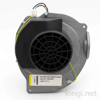
1. Product Overview and Working Principle
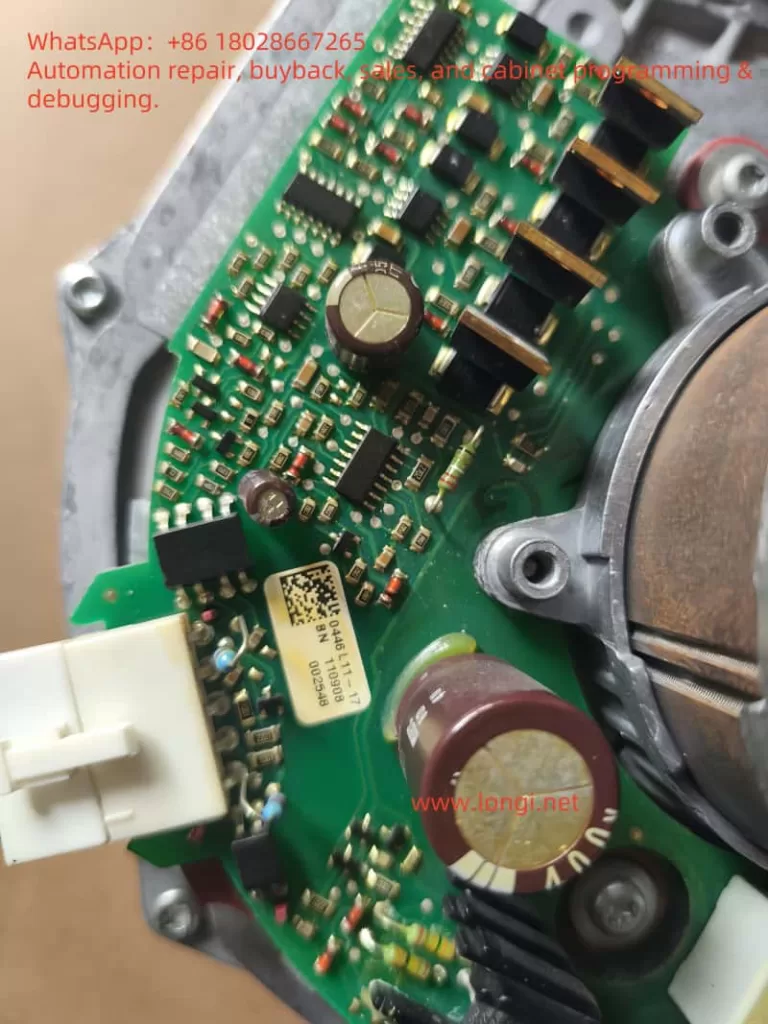
The RG148 series from ebm-papst utilizes EC (Electronically Commutated) motor technology, integrating a rectifier, inverter, and a brushless DC (BLDC) motor into a compact unit. Instead of using a traditional AC induction motor and external variable frequency drive (VFD), these fans convert AC mains to DC internally and use an IGBT inverter to generate three-phase PWM signals that drive the motor.
Key Advantages
- High Efficiency: No belt or rotor copper loss; system efficiency >90%.
- Brushless & Maintenance-Free: No mechanical commutation—electronic switching replaces brushes.
- Easy Speed Control: A simple 1–6 kHz PWM or 0–10 V analog input allows linear speed regulation.
These fans are ideal for applications requiring wide speed ranges, low maintenance, and energy savings of up to 30% compared to traditional setups.
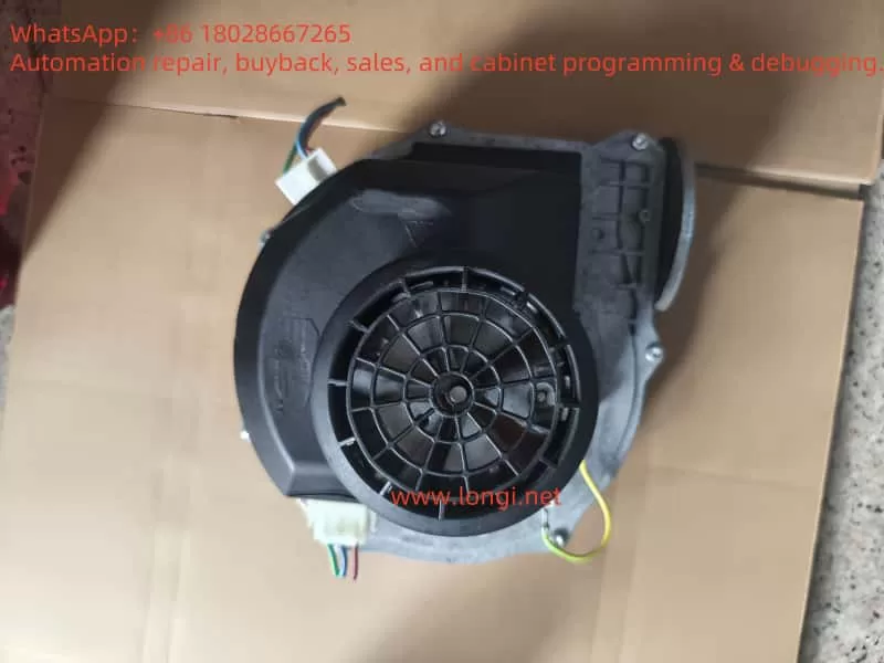
2. Connector Definitions and Wiring
The fan features a 5-pin control connector alongside L/N/PE power terminals. The connector is typically an AMP MATE-N-LOK or Molex Mini-Fit Jr. housing, with pin numbers (“1–5”) molded into the plastic shell.
| Pin | Wire Color (Original Harness) | Function | Description |
|---|---|---|---|
| 1 | Blue | GND (Signal Ground) | SELV ground, isolated from chassis |
| 2 | Yellow | PWM IN / 0–10 V | 1–6 kHz square wave; >20% for startup, >5% for run |
| 3 | — | N.C. (Not Connected) | Reserved |
| 4 | White | Tach Out | 2 pulses/rev, open-collector output |
| 5 | Brown | +18 V Output | Max ~20 mA, for pull-up or optocoupler supply |
How to identify pins:
- Visually inspect the connector for molded pin numbers or orientation notch.
- With power applied, use a multimeter: the only stable ~18 V pair indicates Pin 1 (GND) and Pin 5 (+18 V).
- Injecting PWM into Pin 2 should spin the fan—this helps verify its identity.
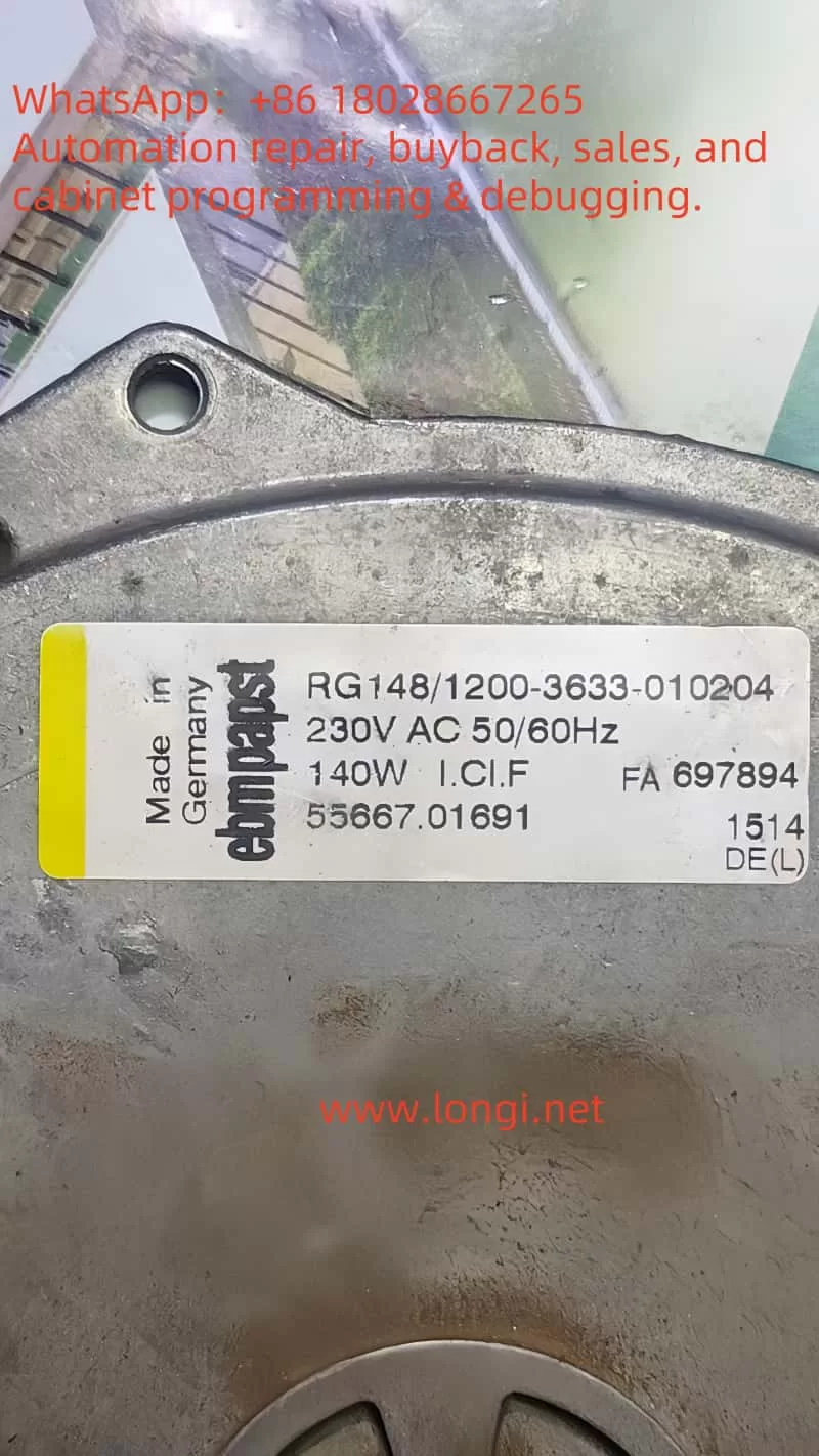
3. Minimal Wiring for Testing
Power Side: Connect L/N to 230 V AC (or 115 V for low-voltage variants). Add a 6 A slow-blow fuse. PE must be grounded for safety.
Control Side (minimum 3 wires):
- Pin 1 → Connect to your microcontroller or function generator GND
- Pin 2 → Feed a 0–5 V PWM signal through a 1 kΩ resistor
- Pin 4 / Pin 5 → Optional; leave unconnected during basic testing
Startup Procedure
- With the fan powered off, complete wiring.
- Power on with PWM = 0%.
- Output a 30% duty PWM (e.g. 3 kHz); the fan should spin up smoothly.
- Adjust duty cycle and observe speed changes.
- Set PWM <3% to stop the fan.
This minimal setup allows safe testing without needing feedback circuits.
4. Tuning Parameters and Performance Verification
| Parameter | Recommended Value | Purpose |
|---|---|---|
| PWM Frequency | 2–4 kHz | Avoids audible noise |
| Startup Duty | ≥25% | Ensures soft start |
| Minimum Duty | >5% | Fan stops below this value |
| RPM Calculation | rpm = freq × 30 | Based on Tach signal (2 p/rev) |
By measuring the Tach frequency and correlating it with airflow or pressure, you can build a duty-RPM-airflow map for system tuning or PID feedback control.
5. Common Faults and Troubleshooting
| Symptom | Possible Cause | Check / Solution |
|---|---|---|
| No rotation | PWM <20%; no GND; internal fuse blown | Oscilloscope on Pin 2; verify Pin 1–5 = +18 V; check fuse |
| Whining or jittering | PWM freq too low; sharp duty changes | Set to 2–4 kHz; ramp the duty smoothly |
| No Tach pulse | Missing pull-up or overvoltage | Pull up Pin 4 to +18 V with 10 kΩ or use voltage divider |
| Overheat shutdown | Poor ventilation; ambient >60°C | Clean airflow path; reduce speed/load |
| EMI interference | Long unshielded wires | Use shielded twisted pairs; add 100 Ω damping resistors on Pin 2/4 |
6. Maintenance and Advanced Configuration
- Routine Check: Every 3 months, clean the impeller and check grounding screws; test insulation yearly.
- Cable Management: For >1 m signal wires, use shielded twisted pairs and ground the shield at one end.
- EEPROM Configuration: Use ebm-papst EC-Control software via Bluetooth or RSB bus to tweak internal parameters (e.g. soft-start ramp, min RPM).
- Harmonic Filtering: For multiple fans on a shared supply, consider adding filters or 12-pulse rectifiers to reduce THDi.
7. Conclusion
The RG148 EC fan series represents a highly efficient and compact solution for modern ventilation systems. With its integrated inverter and brushless motor, it provides wide-speed-range performance without external VFDs. By mastering the 3-wire minimal control method, understanding PWM tuning, and applying basic troubleshooting, engineers can easily integrate and commission these fans in test setups and production lines. For advanced applications, feedback via Tach signals and EEPROM customization further enhances control accuracy and energy efficiency.
This guide aims to provide a comprehensive, practical overview to help users get the fan up and running safely, optimize its performance, and resolve common issues in real-world scenarios.