
I. Equipment Information and Fault Background
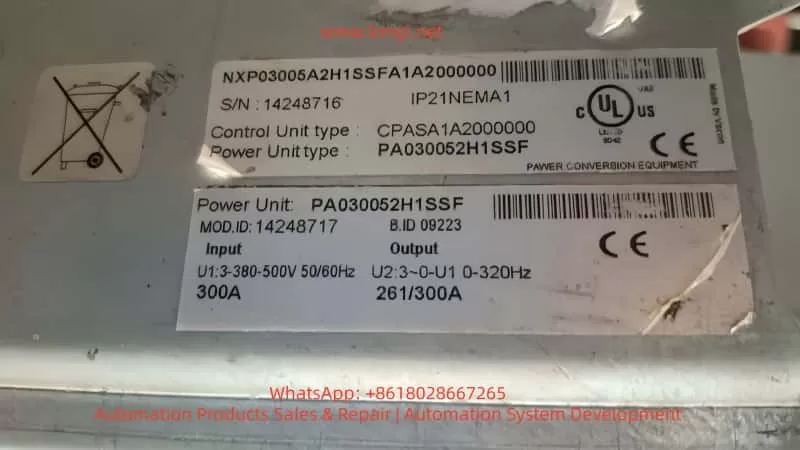
- Frequency Converter Model: VACON NXP03005A2H1SSF
- Power Unit: PA030052H1SSF
- Input Voltage: 3×380–500V, 50/60Hz
- Rated Current: 300A
- Power Board Number: PC00425
- Operating Time: 3 years and 241 days
Customer Description:
“I immediately encountered an F8 fault upon startup. The fault code is S1, with the sub-code indicating a power module and sub-module unit issue. We found that a component on the IGBT circuit board PC00425 had been removed. Q2 is missing. Q3 is still on the circuit board (marked as 4N150).”
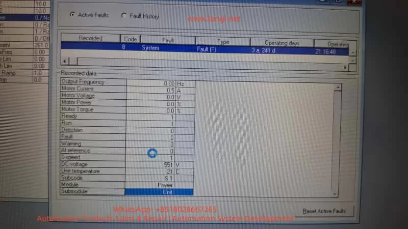
Fault Interface Display:
- Fault: F8 – System Fault
- Module: Power
- Submodule: Unit
- Subcode: S1
- DC-Bus: 551V (normal bus voltage)
- No output established, frequency at 0Hz, fault occurs immediately upon startup
Explanation: This fault occurs during the initial self-check phase of startup, before entering the carrier modulation stage. The root cause is a hardware self-check failure rather than a load or parameter issue.
II. In-depth Interpretation of F8 + S1 Fault Meanings
In the VACON NXP fault system:
- F8 = System Fault (system-level protection, usually indicating hardware anomalies)
The meaning of the S1 sub-code is clearer when combined with the Module/Submodule fields:
| Field | Display | Explanation |
| —- | —- | —- |
| Module | Power | Points to the power unit rather than the control board |
| Submodule | Unit | Indicates the entire power module, not an individual IGBT phase anomaly |
| Subcode | S1 | Pre-charge/discharge/IGBT drive feedback anomalies, hardware handshake failures |
Conclusion:
A communication handshake failure between the control board and the power unit PC00425 or non-compliant voltage/current in the measurement circuit → self-check termination → immediate F8 report.
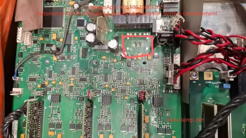
III. Visual Inspection Reveals Key Clue: Missing Q2 MOSFET
On-site Photo Identification:
- The Q2 pad is vacant, and the device has been manually removed.
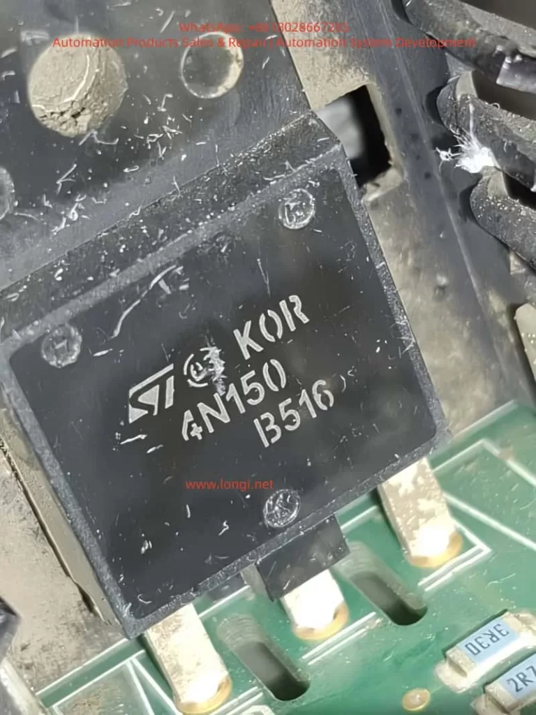
- Adjacent Q3 is still in place, marked with 4N150.
- The component is in a TO-220 package and connected to the heat sink area.
- The pads are intact but show signs of removal, not factory-designed vacancies.
Component Information:
| Device Marking | Silk Screen | Inferred Model | Inferred Function |
|---|---|---|---|
| Q3 | 4N150 | STP4N150 MOSFET (1500V/4A) | Used for bus pre-charge/discharge or gate drive auxiliary switching |
| Q2 | Missing | Should be the same or equivalent model as Q3 | Its absence will cause a break in the logic link → self-check failure |
| Explanation: | |||
| Q2 is not an optional component but a necessary part of the power circuit. The board has likely undergone unprofessional component removal or operated with damage. The missing device will lead to a disconnection in the pre-charge/detection/drive path → immediate F8 occurrence. |
IV. Technical Analysis: Why Does the Lack of One MOSFET Directly Report F8?
In the NXP structure, the power board PC00425 is responsible for:
- IGBT gate drive distribution
- DC bus pre-charge control
- Discharge circuit management
- Voltage/current sampling feedback
- Handshake feedback with the control main board
If Q2/Q3 are used for pre-charge switches, the process is as follows:
Power-on → the drive board sends a charging command to Q2/Q3.
If Q2 is missing → the pre-charge circuit is open.
The DC bus voltage change curve does not meet expectations.
The control board detects an anomaly → self-check interruption.
Immediate entry into F8 System Fault.
Explanation: This explains the phenomenon of “F8 occurring immediately after pressing RUN, before any output,” which is fully logical.
V. Full Repair Process
(1) Power-off/Discharge Safety Confirmation
- The bus must be discharged to below 50V.
- For a 300A-rated device with high energy, high-voltage gloves and insulating shoes are required.
- Never measure power-side devices while powered on.
(2) Essential Basic Tests
| Inspection Item | Judgment Criteria |
|---|---|
| DC+ / DC- to UVW measurement | If there is conduction/low resistance = IGBT breakdown |
| Q3 MOSFET test | No short circuit from gate to ground/no short circuit between DS |
| Q2 pad and surrounding components | Check for burnt or open-circuit resistors, capacitors, and diodes |
| If the IGBT power module is already short-circuited → the IGBT module must be replaced first; otherwise, repairing the board is meaningless. |
(3) Restore Missing Q2
- Recommended model: STP4N150 or a same-specification MOSFET with a voltage rating ≥1500V and Id ≥4A.
- Note: Add insulating pads and thermal grease.
- Simultaneously replace peripheral components such as drive resistors and freewheeling diodes.
(4) First Power-on Must Be Current-limited
Recommended Method:
- Start with a series-connected incandescent lamp or variable resistor.
- Gradually increase the voltage while monitoring the bus.
- Observe whether it passes the self-check and whether the F8 is cleared.
If F8 persists: - Most likely, the drive IC/sampling circuit is damaged, or there is an abnormality in the upper-level control communication.
- It is recommended to replace the entire PC00425 power board for greater reliability.
VI. Final Conclusion
The root cause of the F8 S1 fault reported by the customer’s frequency converter is:
The power board PC00425 has a hardware deficiency (Q2 MOSFET removed), leading to a self-check failure of the power unit and an immediate F8 report, preventing the system from entering operation.
Solution:
- Restore the Q2 device to be the same model as Q3.
- Check and repair surrounding drive and sampling components.
- If the fault persists after repair → it is recommended to replace the entire PC00425 power board.
This case demonstrates:
- Most system faults in VACON NXP are hardware faults at the power module level.
- F8 is usually not a parameter issue, let alone a software fault.
- Powering on with missing components after disassembly and repair → will inevitably lead to a self-check failure and an F8 report.