
Understanding EEPROM Parameter Storage Errors and Full Recovery Methods in Industrial Field Maintenance
Introduction
The ABB ACS501 (also known as SAMI GS series) is an early but highly reliable generation of industrial drives, widely deployed in pumping systems, HVAC, conveyors, and general industrial automation. Many units today have been in service for more than 10–20 years. With aging hardware, environmental stress, and frequent power cycles, one common fault has become a major maintenance topic:
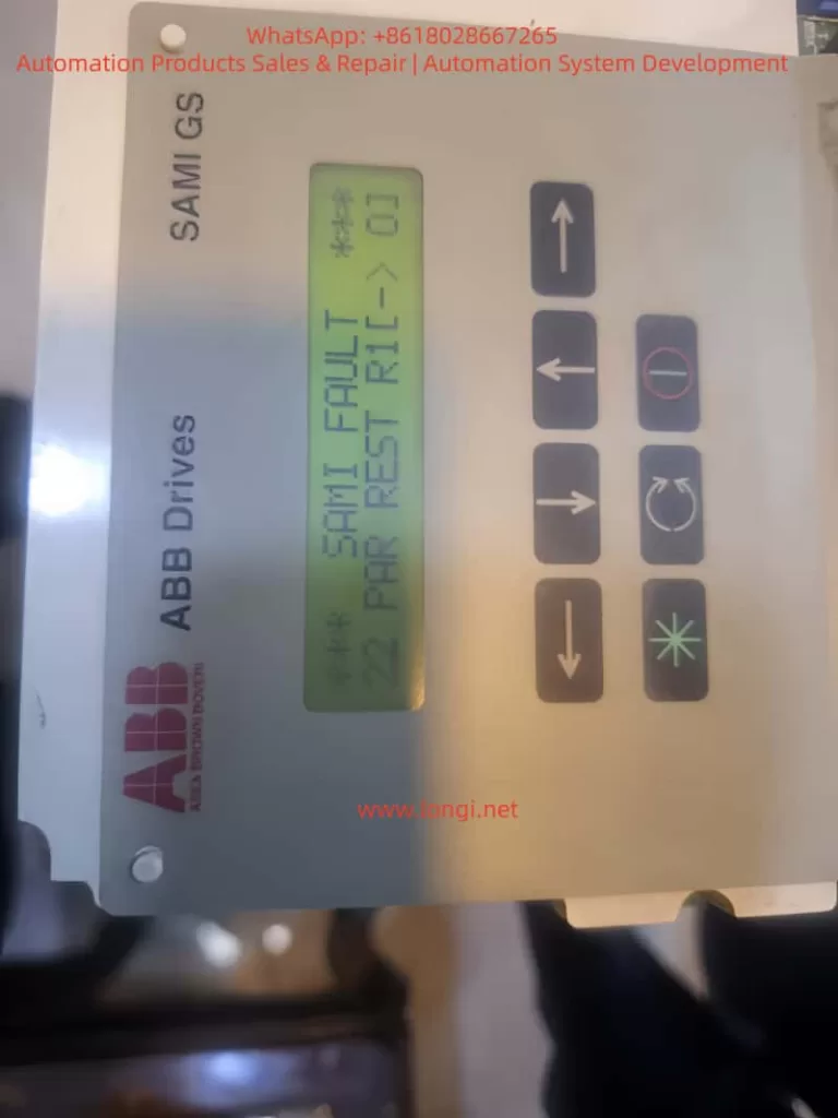
Fault 22 – PAR REST accompanied by Warning – EEPROM WR.
Once this happens, the inverter may fail to store parameters, repeatedly reboot with alarms, and in many cases refuse to run until the parameter system is repaired. Unlike protection faults such as overcurrent or overvoltage, Fault 22 belongs to the memory integrity class of failures, which requires understanding of EEPROM behavior, data checksum logic, and internal parameter structure.
This article aims to provide an independent, practical, and systematically structured guide for diagnosing and repairing this fault. The content is based on real repair cases, technical documentation, and years of on-site maintenance experience. Engineers, maintenance technicians, and equipment owners can rely on this guide to restore functionality effectively.
1. Recognizing the Fault Symptoms
Typical screen displays observed in real cases:
SAMI FAULT
22  PAR REST R1(-)01
and/or
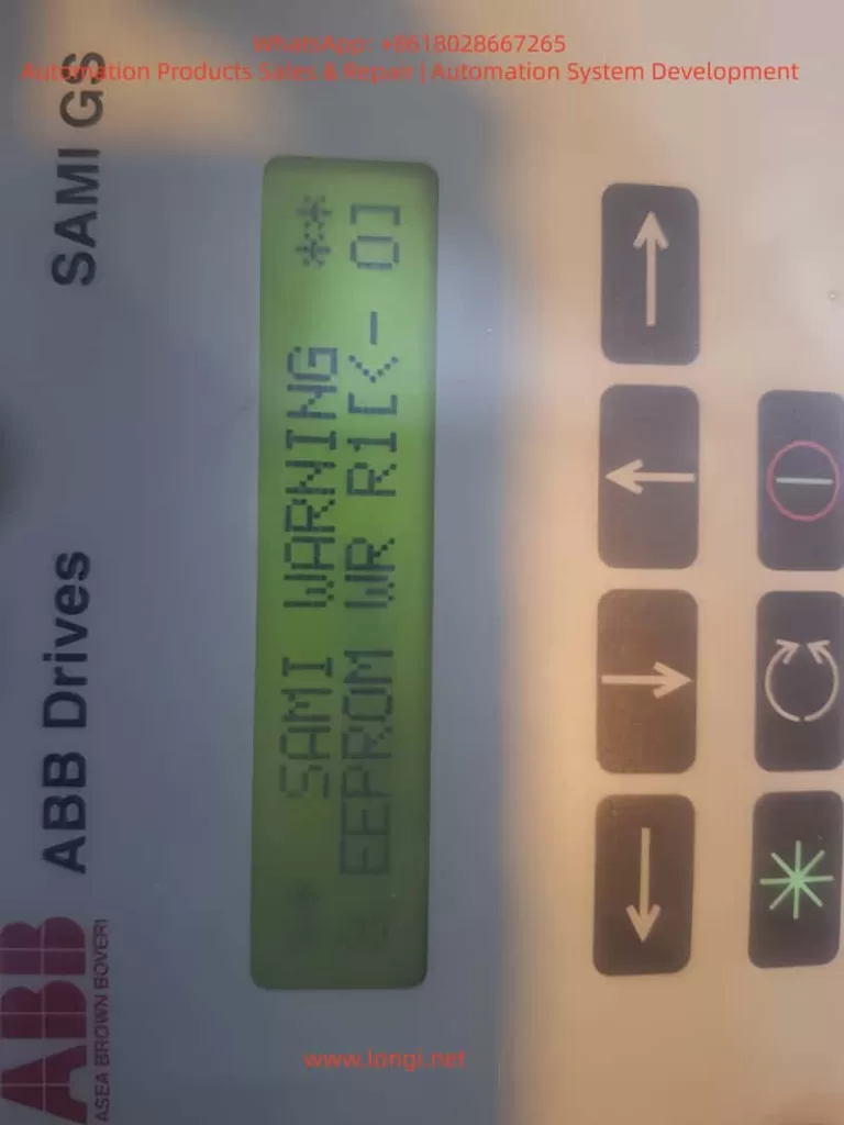
SAMI WARNING
8 EEPROM WR R1(-)01
From the ABB manual:
| Code | Meaning | Consequence |
|---|---|---|
| 22 Par Rest | Parameter checksum mismatch / storage error | Parameter memory considered invalid and must be reset |
| EEPROM WR | Failure or inconsistency during parameter write operation | Drive cannot safely store parameter configuration |
The coexistence of these two messages indicates that the parameter storage block in the EEPROM failed to pass CRC verification. In simple terms:
The drive was unable to read or write its configuration data correctly, so it entered protection status.
If not solved, the drive may not start, or parameters will disappear after every power cycle.
2. Why This Fault Happens – Root Cause Mechanism
Understanding the cause is crucial before taking action. The ACS501 uses internal EEPROM to store key parameters, including:
- startup configuration
- motor nameplate data
- application macro and limits
- protection settings
- frequency scaling and control mode
On startup, the firmware loads parameters and verifies data integrity. When CRC fails or EEPROM read/write is unstable, the drive issues Fault 22 Par Rest.
Based on repair statistics, the root causes can be grouped into five main categories:
- EEPROM Aging and Memory Wear
- Drives older than 10 years frequently experience write failure
- Parameters can be changed, but revert to defaults after power-off
- Power interruption during write operation
- Sudden shutdown, unstable grid supply, contactor chatter
- Parameter commit not completed → broken data block → CRC error
- Electrical noise or grounding issues
- Poor shielding, inverter room welding, lightning surge
- Interfered I²C communication during write cycles
- Control board 5V power ripple increases with age
- Dried capacitors → unstable MCU/EEPROM communication
- Incorrect board replacement or parameter import
- Parameters from another inverter model loaded → mismatch
In short:
Fault 22 is not a running fault; it is a memory integrity failure.
Fixing it means restoring EEPROM write/read capability.
3. Step-by-Step Troubleshooting and Repair Procedure
For field engineers, the most efficient approach is to follow a staged repair workflow:
Stage A – Software Recovery (No Hardware Disassembly)
This should always be attempted first.
Method 1: Factory Restore (Official Procedure)
- Power ON the drive
- Enter menu Start-up Settings
- Set C – Applic. Restore = YES
- Save and exit
- Power OFF for 60 seconds
- Power ON again and observe
If the fault disappears, the EEPROM structure was corrected successfully.
Method 2: Full Macro Reset and Parameter Rewrite
- In Start-up menu
- B – Application = Factory
- C – Applic.Restore = YES
- Save parameters
- Cycle power again
Then test EEPROM:
- Modify a parameter (e.g. max frequency 50Hz → 48Hz)
- Save → Power OFF → ON
- Check if value persists
If parameters still reset after power cycle → EEPROM write failure confirmed → proceed to hardware stage.
Stage B – Hardware-Level Repair (Advanced)
Applicable when software reset does not fix the issue.
Step B1: Inspect EEPROM Read/Write Behavior
Use oscilloscope or logic analyzer to observe SDA & SCL communication:
| Normal condition | Abnormal condition |
|---|---|
| stable square wave signals during boot | missing pulses / irregular edges |
| ACK bits received consistently | collisions or stuck bus |
| voltages around 3.3/5V as design | sagging or unstable waveform |
If unstable signals are found → likely cause:
| Possible cause | Repair action |
|---|---|
| 24C02/24C04 EEPROM chip worn out | Replace with new EEPROM |
| Pull-up resistors drifted | Replace 4.7k~10k resistors |
| 5V power ripple >50mV | Replace electrolytic capacitors & regulator |
| MCU/I²C solder cracks | Reflow solder joints |
Replacing EEPROM requires parameter reconstruction if original data unreadable.
Step B2: EEPROM Programming Solutions
There are three strategies depending on data availability:
| Approach | Use Case |
|---|---|
| Clone from another working ACS501 same power rating | Best for rapid recovery |
| Load generic factory parameter template | Suitable for basic fan/pump load |
| Manual reconfiguration from motor nameplate | Slow but effective |
Critical parameters to record BEFORE chip replacement:
| Parameter | Source |
|---|---|
| Rated motor current & power | Motor nameplate |
| Supply voltage, frequency | Startup menu D |
| Cos phi, slip compensation | Nameplate & defaults |
| V/f curve, weak field | Default = 50Hz |
| Accel/Decel time | Default 3s |
Once EEPROM is flashed successfully, repeat software restore to rebuild data structure.
4. Practical Summary from Real Case Experience
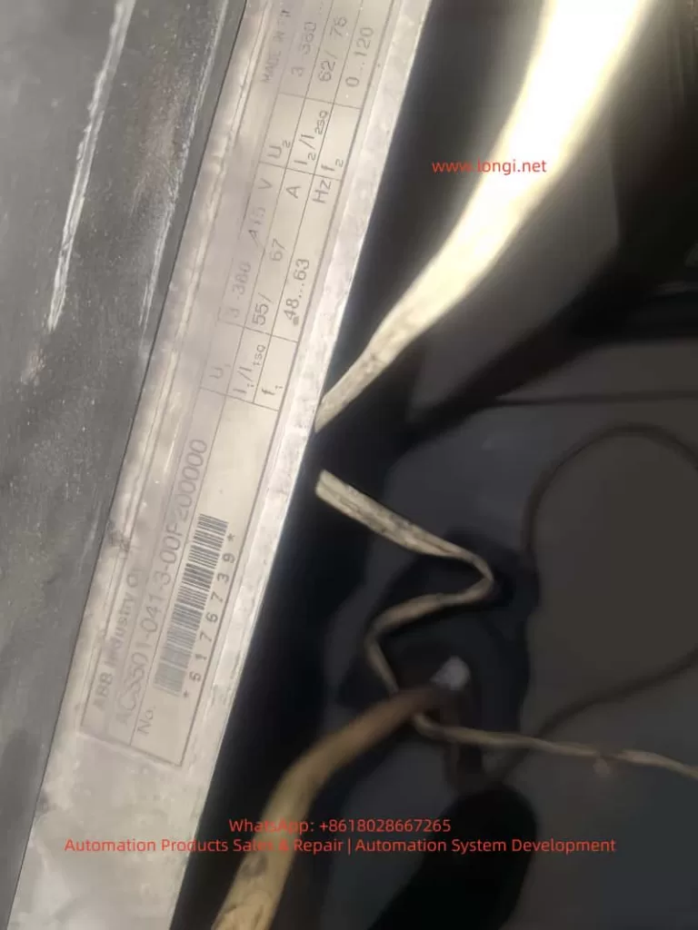
Based on the photographed inverter:
Model: ACS501-041-3 (approx. 37kW)
Age > 10 years → EEPROM aging probability extremely high.
Key conclusions:
- 22 Par Rest + EEPROM WR together = memory error almost certain
- If parameters cannot be saved → hardware repair required
- High success rate from EEPROM replacement + reprogramming
- Always backup parameters after repair
Recommended workflow:
Software fix → Parameter rebuild → EEPROM replacement → Control board repair
5. Preventive Measures to Reduce Recurrence
| Recommendation | Benefit |
|---|---|
| Use UPS or avoid power-off during parameter writing | Prevent data corruption |
| Annual parameter backup for old drives | Quick restoration in emergencies |
| Replace EEPROM & capacitors proactively after 10 years | Prevent failure before it occurs |
| Ensure grounding and shielded wiring | Reduce I²C communication interference |
The failure is progressive, not sudden. Early attention saves downtime cost.
Conclusion
The ABB ACS501/SAMI GS is a robust drive platform with high maintainability. Fault 22 Par Rest is not a dead-end failure; in most cases, it simply indicates corrupted EEPROM data that can be restored with systematic procedures.
Through this article, we explored:
• What Fault 22 means
• Why EEPROM errors occur
• Complete step-by-step recovery workflow
• Hardware repair techniques & parameter reconstruction
• Preventive strategies to increase long-term reliability
For engineers, understanding this fault transforms a seemingly serious shutdown into a solvable maintenance task. With the correct approach, the inverter can return to full operation with minimal downtime.