
Introduction
Servo drives, as the core control components of industrial automation equipment, directly determine the operational efficiency and production continuity of devices. The HiMEC HI2xx series servo drives, renowned for their high cost performance and user-friendliness, are widely applied in machine tools, robots, packaging machinery, and other fields. However, in practical use, the ERCON fault (flashing display) caused by communication interruption between the operator (e.g., drive panel) and the main board is one of the most common issues. If unresolved promptly, it can lead to equipment downtime and production stagnation. This article delves into the root causes of the ERCON fault in HI2xx series drives, provides a step-by-step solution guide, and proposes preventive measures to help technicians quickly locate and resolve the problem.
1. Overview of ERCON Fault
1.1 Fault Definition
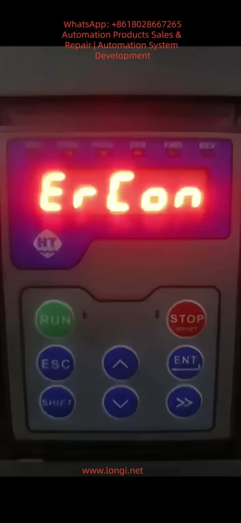
ERCON (Error Communication) is a communication fault code specific to HiMEC HI2xx series drives, referring to the interruption of the communication link between the operator (e.g., drive panel, handheld programmer) and the main board. When the communication link is abnormal, the operator triggers a communication alarm and displays “ERCON” in a flashing manner, alerting users to check the communication system immediately.
1.2 Fault Impact
- The operator cannot receive status information from the main board (e.g., motor speed, torque, alarm codes);
- Control commands (e.g., start, stop, parameter modification) cannot be sent to the main board;
- The drive enters protection mode, unable to drive the motor normally, and may cause equipment shutdown in severe cases.
2. In-Depth Analysis of Fault Causes
The communication link of HI2xx series drives consists of three parts: operator, communication cable, and main board interface (Figure 1). Any abnormality in these components can trigger the ERCON fault. Below is a detailed breakdown of the causes:
2.1 Communication Cable Fault (Most Common Cause)
The communication cable is the “signal bridge” connecting the operator and the main board, accounting for over 60% of ERCON faults. Specific causes include:
- Physical damage: Internal conductors break due to long-term vibration or bending (e.g., copper foil fracture in a flat cable);
- Loose connection: Poor contact between the plug and socket due to vibration or repeated插拔 (e.g., reduced clamping force between a pin header and socket);
- Electromagnetic interference (EMI): The communication cable is not shielded or laid parallel to power cables (e.g., motor cables), causing EMI to disrupt communication (e.g., RS485 differential signals are submerged by noise);
- Aging: The insulation layer of the communication cable ages due to high temperature or humidity, leading to short circuits or signal attenuation.
2.2 Interface Fault
The communication interfaces of the operator or main board are “nodes” in the link, accounting for about 30% of faults. Specific causes include:
- Pin damage: Pins (e.g., pin header, DB9 interface pins) bend or break due to forced插拔 or vibration (e.g., a pin header pin is bent and cannot contact the socket);
- Oxidation/contamination: Pins oxidize (e.g., copper pins turn black) or the interface is contaminated with dust/oil in humid/dusty environments, increasing contact resistance and blocking signal transmission;
- Lock failure: The plug lock (e.g., flat cable clip) breaks due to aging, causing the plug to loosen and lose contact.
2.3 Equipment Itself Fault
Faults in the internal communication circuits of the operator or main board account for about 10% of cases. Specific causes include:
- Operator fault: The operator’s communication chip (e.g., RS485 transceiver) is damaged, unable to send/receive signals;
- Main board fault: The main board’s communication interface circuit (e.g., UART, RS485 circuit) fails (e.g., capacitor breakdown, resistor burnout), preventing signal processing;
- Firmware incompatibility: Mismatched firmware versions between the operator and main board (e.g., the operator’s firmware is upgraded but incompatible with the old main board’s communication protocol) disrupt communication.
2.4 Environmental Factors
- Excessive temperature: The operating environment exceeds the rated range (e.g., HI2xx series operates at 0–45°C), softening the communication cable’s insulation or loosening solder joints on interface pins;
- High humidity: Ambient humidity exceeds 85%, accelerating pin oxidation or reducing the communication cable’s insulation resistance (e.g., insulation resistance drops from 10MΩ to <1MΩ, causing severe signal attenuation);
- Vibration: Long-term operation in high-vibration environments (e.g., presses, vibration tables) loosens communication cable plugs or breaks internal conductors.
3. Step-by-Step Solution Guide for ERCON Fault
The following steps follow the principle of “from simple to complex, from external to internal” to help technicians troubleshoot without盲目 disassembling the device.
3.1 Step 1: Power Off and Preliminary Inspection
Purpose: Ensure safety and avoid damaging the device during live operations;初步 locate the fault scope.
Details:
- Power off: Turn off the drive’s power switch (e.g., circuit breaker) and unplug the power cord. Wait 5 minutes to discharge the drive’s internal capacitors;
- Visual inspection:
- Check the communication cable for obvious breaks, bends, or insulation damage (e.g., exposed copper foil in a flat cable);
- Check the connection between the plug and socket for looseness (e.g., the flat cable plug is not fully inserted into the socket);
- Check the operator and main board interfaces for dust or oil (e.g., black dust in the interface);
- Re-plug the communication cable:
- Release the plug lock (e.g., flat cable clip) and slowly pull out the plug;
- Check the plug pins for bending or breakage (e.g., a pin header pin is bent);
- Brush dust from the plug and socket with a brush, then reinsert the plug and ensure the lock is fastened (e.g., the flat cable clip is fully locked).
Notes:
- Align the pins when plugging/unplugging to avoid bending pins with force;
- Replace the communication cable if the plug lock fails (avoid using tape, which can cause poor contact).
3.2 Step 2: Continuity Test of Communication Cable
Purpose: Verify if the communication cable has internal breaks and eliminate conductor faults.
Details:
- Prepare tools: Multimeter (set to “continuity mode” or “resistance mode”);
- Test method:
- Connect both ends of the communication cable to the operator and main board interfaces (e.g., insert both ends of the flat cable into the operator and main board sockets);
- Touch the corresponding pins of the communication cable with multimeter probes (e.g., pin 1 to pin 1, pin 2 to pin 2, etc.);
- If the multimeter shows “continuity” (resistance <1Ω), the conductor is normal; if it shows “open circuit” (infinite resistance), the conductor is broken.
Example:
- If pin 3 of the communication cable is not continuous to pin 3, the 3rd conductor is broken and the cable needs replacement.
Notes:
- Ensure both ends of the communication cable are not connected to the operator or main board during testing (to avoid interference from the main board circuit);
- If the communication cable is a shielded type, test the shield continuity (the shield must be grounded to avoid EMI).
3.3 Step 3: Interface Inspection and Cleaning
Purpose: Eliminate poor contact caused by pin damage, oxidation, or contamination.
Details:
- Inspect pins:
- Use a magnifying glass to check interface pins (e.g., socket pins): look for bending or breakage (e.g., a socket pin is bent);
- If a pin is bent, slowly adjust it to vertical with tweezers (avoid excessive force to prevent breakage);
- If a pin is broken, replace the interface (e.g., socket) or main board (if the pin is soldered to the main board).
- Clean oxidation and dust:
- Soak a cotton swab in anhydrous alcohol (≥99% concentration) and wipe the interface pins (e.g., socket pins, plug pins);
- Brush dust from the interface with a brush;
- Reinsert the communication cable after the alcohol evaporates.
Notes:
- Do not grind pins with sandpaper (this damages the pin coating and accelerates oxidation);
- Use anhydrous alcohol to clean oil stains (avoid corrosive solvents like gasoline or thinner).
3.4 Step 4: Replace the Communication Cable
Purpose: Eliminate faults caused by the communication cable itself (e.g., internal breaks, aging).
Details:
- Select the communication cable:
- Use a HiMEC original communication cable (matching the HI2xx series drive model, e.g., HI2-CABLE-01);
- If an original cable is unavailable, use a shielded communication cable of the same specification (e.g., RS485 communication cables must be twisted-pair with a shield, and the shield must be grounded).
- Replacement method:
- Disconnect both ends of the old communication cable (operator and main board sides);
- Insert both ends of the new communication cable into the operator and main board interfaces, ensuring the lock is fastened;
- Power on the drive: if the ERCON fault disappears, the communication cable fault is resolved.
Notes:
- Do not use non-original communication cables (incorrect pinout or impedance mismatch may cause communication faults);
- If the ERCON fault persists after replacing the cable, check the operator and main board interfaces for damage (e.g., bent pins).
3.5 Step 5: Firmware Inspection for Operator and Main Board
Purpose: Eliminate communication faults caused by firmware incompatibility.
Details:
- Check firmware versions:
- View the operator’s firmware version via the menu (e.g., “Parameter Settings” → “Version Information”);
- View the main board’s firmware version via the drive’s upper computer software (e.g., HiMEC Servo Tool);
- Upgrade firmware:
- If the operator and main board firmware versions are mismatched (e.g., operator firmware V1.2, main board firmware V1.0), upgrade to a compatible version (e.g., both to V1.3);
- Follow HiMEC’s Firmware Upgrade Guide for firmware upgrades (e.g., via USB or SD card) to avoid device damage.
Notes:
- Backup parameters before firmware upgrades (to avoid parameter loss after upgrading);
- Do not upgrade to unvalidated firmware versions (may cause communication protocol incompatibility).
3.6 Step 6: Hardware Inspection of Main Board and Operator
Purpose: Eliminate hardware faults in the operator or main board (e.g., damaged communication circuits).
Details:
- Replacement test:
- If a spare operator is available (e.g., the same model panel), replace the original operator. If the ERCON fault disappears, the original operator is faulty;
- If a spare main board is available (e.g., the same model main board), replace the original main board. If the ERCON fault disappears, the original main board is faulty.
- Circuit testing:
- Use a multimeter to test the voltage of the main board’s communication interface (e.g., RS485 interface voltage: normally 1–5V between A+ and B-);
- Use an oscilloscope to test the communication signal (e.g., RS485 differential signal: normally clear waveform without noise);
- If the voltage or signal is abnormal, repair or replace the main board (e.g., replace the communication circuit chip or resistor).
Notes:
- Use the same model of device for replacement tests (to avoid compatibility issues);
- Circuit testing must be performed by a professional technician (to avoid damaging other circuits).
4. Preventive Measures for ERCON Fault
4.1 Regularly Inspect the Communication Link
- Weekly check: Visually inspect if the communication cable is loosely connected or damaged (e.g., flat cable copper foil breakage);
- Monthly check: Test the communication cable’s continuity with a multimeter (to avoid internal conductor breaks);
- Quarterly check: Clean dust and oxidation from the operator and main board interfaces (to avoid poor contact).
4.2 Environmental Maintenance
- Temperature control: Keep the drive’s operating environment between 0–45°C (e.g., install cooling fans, avoid direct sunlight);
- Humidity control: Maintain ambient humidity between 40%–85% (e.g., install dehumidifiers, avoid exposing the device to rain);
- Vibration protection: Install the drive in a low-vibration area (e.g., fix the device with shock-absorbing pads) to prevent communication cable breaks due to vibration.
4.3 Standardize Operations
- Plug/unplug communication cables: Align the pins and avoid forced insertion (e.g., use the lock to fix, avoid pulling out pins);
- Firmware upgrades: Follow the manufacturer’s guide (e.g., backup parameters, use a stable power supply) to avoid upgrade failures;
- Avoid EMI: Lay communication cables separately from power cables (e.g., spacing >30cm) or use shielded communication cables (the shield must be grounded).
4.4 Spare Parts Management
- Stock original communication cables (e.g., HI2-CABLE-01), spare operators (e.g., same model panel), and spare main boards (e.g., same model main board) to enable quick replacement and reduce downtime.
5. Case Analysis
5.1 Fault Phenomenon
An HI200-01 drive in a packaging machinery factory (controlling a feeder motor for a packaging machine) displayed a flashing “ERCON” after power-on, and the motor could not start.
5.2 Troubleshooting Process
- Step 1: Re-plugging the communication cable after power-off did not resolve the fault;
- Step 2: A multimeter test showed an open circuit between pin 3 of the communication cable (internal conductor break);
- Step 3: Replacing the original communication cable (HI2-CABLE-01) eliminated the ERCON fault, and the operator displayed normally.
5.3 Root Cause
The communication cable’s internal conductor broke due to long-term vibration from the packaging machine, interrupting the communication link.
5.4 Result
The device resumed normal operation after replacing the communication cable, and no further ERCON faults occurred.
6. Conclusion
The ERCON fault is a common communication fault in HiMEC HI2xx series drives, caused by communication link interruption. Technicians can quickly locate and resolve the problem by following the steps: power off and inspect → test communication cable → clean interfaces → replace communication cable → check firmware → inspect hardware. Additionally, preventive measures such as regular inspections, environmental maintenance, standardized operations, and spare parts management can effectively reduce the occurrence of ERCON faults and ensure stable device operation.
The solution guide and preventive measures in this article are not only applicable to HI2xx series drives but also provide a reference for troubleshooting communication faults in other servo drives. Technicians should adjust the troubleshooting steps flexibly based on specific device conditions (e.g., environment, frequency of use) to ensure rapid recovery of device operation.