
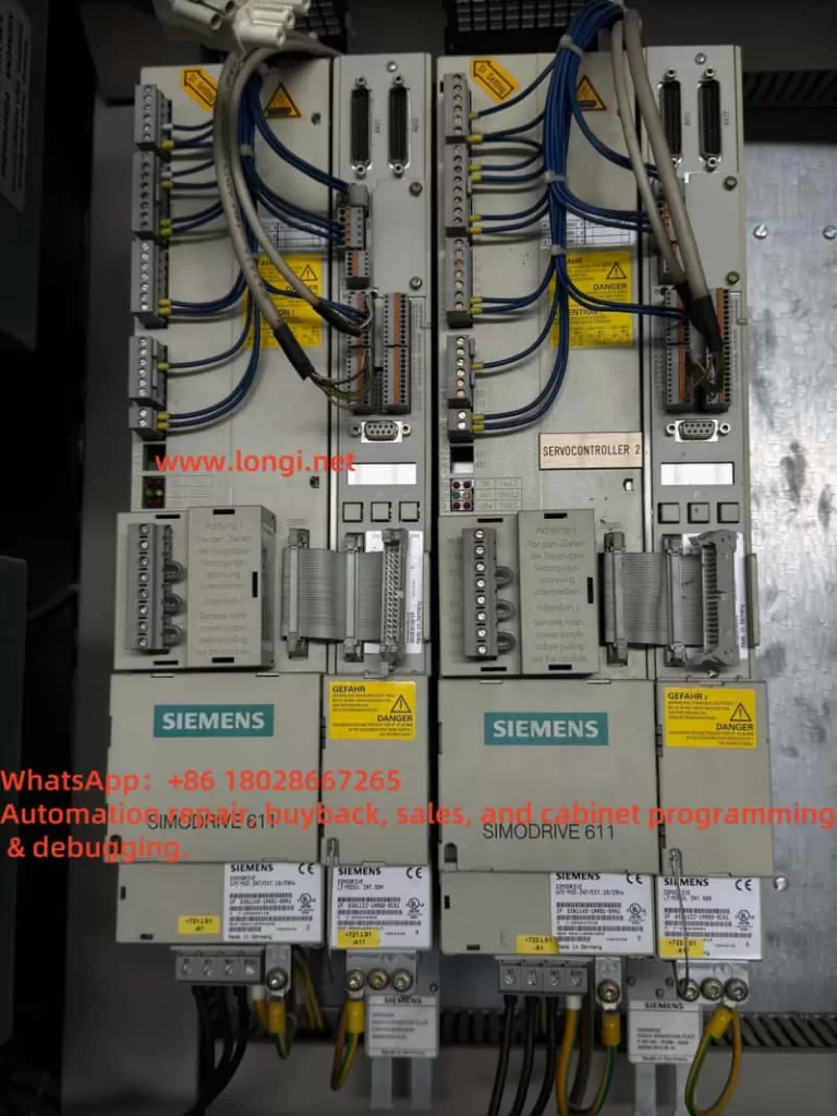
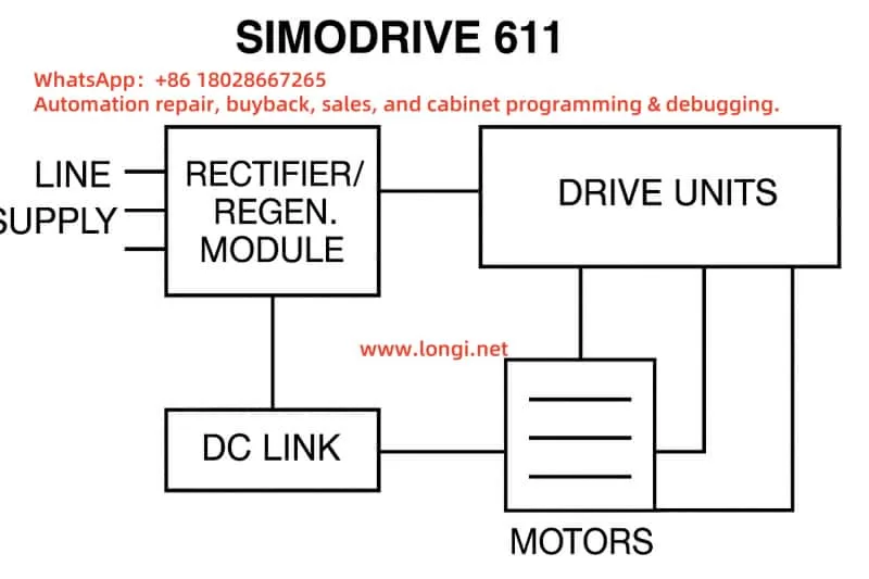
Siemens SIMODRIVE 611 is a modular, high-performance servo/spindle drive system widely used in CNC machines, automated production lines, high-speed machining centers, and other industrial applications. The system comprises a power module (rectifier/regenerative unit), drive modules (UM/FM), and control interface units, forming a complete motion control solution.
This article provides a comprehensive analysis of the SIMODRIVE 611 system, covering its functional description, standard wiring methods, parameter setting and commissioning steps, common fault diagnosis, and practical maintenance tips.
I. Functional Overview of SIMODRIVE 611 System
1. Power Module (E/R Module)
- Model example: 6SN1146-1BB00-0EA1, a rectifier + regenerative feedback module.
- Main function: Converts 3-phase AC power (380V
480V) into DC link voltage (typically 540V600V DC), and feeds back braking energy to the grid during motor deceleration. - Features fault indication lights (RED/GREEN/YELLOW), supports pre-charging, DC discharge, and electronic monitoring.
2. Drive Modules
- Includes UM (Universal Module) and FM (Spindle Module).
- Responsible for controlling the motion of servo/spindle motors, including speed, torque, and position regulation.
3. Control Interface Modules
- Provide signal handling for PROFIBUS, analog I/O, power/enable feedback, encoder feedback, and more.
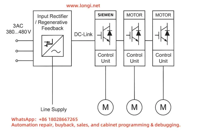
II. Wiring Methods and Interface Descriptions
1. Power Module Wiring
- Input: 3-phase AC supply 3AC 380~480V
- Output: DC-Link voltage connected to drive modules
- X111 terminal block wiring:
- T48-112-9: Checks whether the DC bus is charged
- T63-9 / T64-9: Controls power enable for the drive module
- Terminals T74/T73: Startup signal status (Open/Closed determines power state)
- T5.1 / T5.2 / T5.3: Motor over-temperature, braking resistor, and drive fault alarm inputs
2. Wiring Precautions
- X181 port terminals NS1-NS2 must be shorted; otherwise, the system will not power up
- Never connect wires while the module is powered on
- Discharge circuits should be used to safely eliminate residual DC bus voltage
III. Parameter Setting and Commissioning
SIMODRIVE 611 parameters are configured using Siemens’ SimoCom U software tool.
1. Required Tools
- SimoCom U software (Windows compatible)
- Communication cable (RS232 or USB-to-RS232 converter)
- Connect to the module via X471 communication port
2. Parameter Setup Procedure
- Establish communication between PC and module
- Read the current parameter set
- Configure essential parameters:
- Power module identification (Pn1)
- Encoder type and feedback (Pn11~Pn13)
- Current limits, acceleration/deceleration times (Pn30, Pn35, etc.)
- Alarm thresholds (voltage, current, temperature)
- Save settings and reboot the system for changes to take effect
IV. Fault Diagnosis and Maintenance Tips
SIMODRIVE 611 features comprehensive fault diagnostics through LED indicators and signal terminals. Voltage and logic signal checks can quickly help pinpoint issues.
1. LED Status Indicators
- RED: Electronic hardware fault (e.g., DC bus failure, power fault)
- YELLOW: Pre-charging or module not ready
- GREEN: System is operating normally
2. Common Fault Cases
Case 1: T48-112-9 Not Conducting
- Symptom: DC bus voltage is only 27V after power-on, green LED is lit
- Possible causes: NS1-NS2 on X181 not shorted, pre-charge failure, protection not cleared
Case 2: T63-9 / T64-9 Not Conducting
- Symptom: Drive module inactive
- Troubleshooting: Manually short T63-9 and T64-9; if no response, check control board or upstream enable signal
Case 3: Constant RED Light
- Symptom: Module powered but no output
- Troubleshooting: Verify terminal shorts, drive connections, and presence of critical alarm codes
3. Maintenance Tips
- Diagnosis order: Check low-voltage logic terminals first (e.g., X111), then inspect if DC bus voltage is established
- Use a multimeter for voltage and continuity checks (especially at control terminals)
- Use a T20 Torx screwdriver to disassemble modules—avoid using incorrect tools
- Wait at least 5 minutes after power-off before performing any service work due to high residual voltage
V. Conclusion
SIMODRIVE 611 is a robust and well-designed industrial drive system. Its power modules not only rectify three-phase AC to DC but also provide regenerative feedback capability, making it highly efficient. For optimal performance and safe maintenance, correct parameter configuration, proper wiring, and methodical troubleshooting are essential.
This article aims to provide engineers and maintenance personnel with a complete overview of SIMODRIVE 611’s operation and diagnostics. For advanced customization or onsite support, please consult Siemens-certified service providers or original factory support.