
Introduction
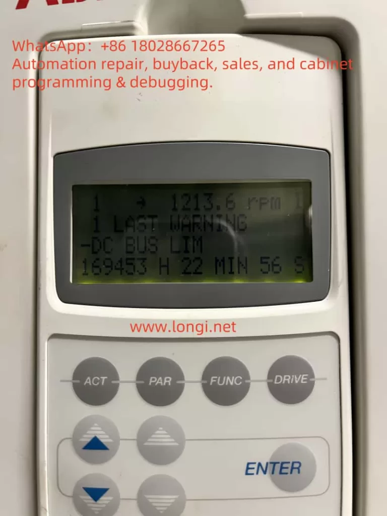
The ABB ACS800 series of frequency converters are core components in the industrial automation sector, widely used in industries such as papermaking, metals, mining, power, and chemicals. With a power range spanning from 0.75 hp to 7500 hp, they are adaptable to various complex application scenarios. However, during operation, the frequency converter may display warning or fault codes, among which “DC BUS lim” (code 3211) is a common informational alert. This warning indicates an abnormal DC bus voltage, potentially affecting device performance and even system safety. Understanding the meaning, causes, and solutions for the “DC BUS lim” warning is crucial for ensuring stable device operation and extending its service life.
This article will delve into the definition, triggering conditions, diagnostic steps, solutions, and preventive measures for the “DC BUS lim” warning, providing comprehensive guidance for users.
Part 1: Understanding the “DC BUS lim” Warning
1.1 Definition of the Warning
The “DC BUS lim” warning is an informational alert in the ABB ACS800 frequency converter, identified by code 3211 and associated with status bit 03.18 ALARM WORD 5 (bit 15). It indicates that the DC bus voltage in the intermediate circuit of the frequency converter has reached the supervisory limit range (either too high or too low), prompting the frequency converter to limit output torque to protect itself and connected equipment. This warning is controlled by the programmable fault function parameter 30.23 (bit 1) and is part of the protection mechanism.
Key Characteristics:
- Type: Informational alert (does not cause immediate device shutdown).
- Code: 3211 (some documents may reference 7114, depending on firmware version).
- Impact: Torque limitation may lead to reduced performance, but the device remains operational.
1.2 Triggering Conditions for the Warning
The “DC BUS lim” warning is typically triggered under the following conditions:
- High DC Bus Voltage: Exceeds the maximum allowable value for the device (e.g., 728V for 400V series, 877V for 500V series, and 1210V for 690V series).
- Low DC Bus Voltage: Falls below the minimum value for the device (e.g., 307V for 400V and 500V series, 425V for 690V series).
These voltage anomalies may be caused by external power supply issues or internal load characteristics.
Part 2: Common Causes of the “DC BUS lim” Warning
The following are the primary reasons for the “DC BUS lim” warning:
2.1 High Input Voltage
- Description: The input AC power supply voltage exceeds the frequency converter’s specifications (e.g., 380–415V for 400V series, 380–500V for 500V series).
- Impact: High input voltage directly leads to an increase in DC bus voltage, triggering the warning.
- Example Scenario: Abnormal grid voltage or incorrect transformer configuration.
2.2 Load Regeneration Energy
- Description: During rapid deceleration or overloading (e.g., lowering heavy loads), the motor may feed energy back into the DC bus, causing the voltage to rise.
- Impact: If the regenerated energy is not effectively dissipated, it can push up the DC bus voltage.
- Example Scenario: Rapid descent of a crane or sudden deceleration of a high-speed motor.
2.3 Power Supply Instability
- Description: Power loss (e.g., single-phase failure), damaged fuses, or unstable grid conditions may cause fluctuations in the DC bus voltage.
- Impact: Low or unstable voltage may trigger the warning.
- Example Scenario: Aging grid infrastructure or interference caused by other equipment in the factory.
2.4 Voltage Fluctuations
- Description: Switching operations of other equipment on the grid may cause transient voltage changes.
- Impact: These fluctuations may cause the DC bus voltage to briefly exceed the normal range.
- Example Scenario: Startup or shutdown of large motors.
Part 3: Diagnosing the “DC BUS lim” Warning
Accurate diagnosis is a prerequisite for resolving the warning. The following are recommended diagnostic steps:
3.1 Check Input Power Supply Voltage
- Steps: Use a multimeter to measure the phase-to-phase voltage of the input AC power supply, ensuring it is within the device’s specifications (e.g., 380–415V for 400V series).
- Considerations: Check for single-phase loss, damaged fuses, or loose wiring.
- Tools: High-precision multimeter.
3.2 Monitor DC Bus Voltage
- Steps: View the DC bus voltage through the frequency converter’s control panel or an external measuring device.
- Reference Values:
- 400V Series: Approximately 540V (normal operation).
- 500V Series: Approximately 680V.
- 690V Series: Approximately 950V.
- Abnormal Conditions: If the voltage is significantly high (approaching or exceeding 728V, 877V, or 1210V) or low (below 307V or 425V), further investigation is required.
3.3 Review Fault History Records
- Steps: Access the control panel, navigate to parameter group 30 (fault functions) or the fault history records, and check for other related warnings (e.g., “DC OVERVOLTAGE” or “DC UNDERVOLTAGE”).
- Purpose: Determine the frequency of the warning and possible associated issues.
3.4 Check Relevant Parameters
- Parameter 95.07 (LCU DC REF): Confirm that the DC voltage reference value (0–1100V) is correctly set.
- Parameter 30.23 (Fault Function): Check if bit 1 (DC BUS lim) is activated (default may be 0). If triggered frequently, consider adjusting.
Part 4: Resolving the “DC BUS lim” Warning
Based on the diagnostic results, the following measures can be taken to resolve the issue:
4.1 Adjust Operating Parameters
- Measures:
- Reduce Load: If the load is too heavy, reducing it can decrease the regenerated energy.
- Adjust Acceleration/Deceleration Time: Modify parameters in parameter group 22 (acceleration/deceleration) to extend the deceleration time and reduce voltage spikes.
- Example: Increase the deceleration time from 5 seconds to 10 seconds and observe if the warning disappears.
4.2 Install Braking Resistors and Brakes
- Measures: If the application involves frequent deceleration or regenerated energy, install braking resistors and brakes (controlled by parameter group 27, e.g., 20.05 and 14.01).
- Function: Braking resistors stabilize the DC bus voltage by dissipating excess energy.
- Note: Ensure the braking resistor’s specifications match the frequency converter.
4.3 Modify Fault Function Parameters
- Measures: Access parameter group 30 and adjust parameter 30.23:
- The default value may be 0 (bit 1 not activated).
- Set to 3 (activate bits 0 and 1) to enable the warning, or disable it (if triggered frequently without affecting operation).
- Note: Back up parameters before adjusting to ensure system safety.
4.4 Ensure Power Supply Stability
- Measures:
- Use voltage stabilizers or UPS systems to improve power quality.
- Check power lines for loose or damaged connections.
- Tools: Power quality analyzers.
4.5 Enable Automatic Reset Function
- Measures: Use parameter group 31 (automatic reset) to set up overvoltage/undervoltage automatic reset, helping the frequency converter recover after brief anomalies.
- Note: Only suitable for transient issues; long-term problems require fundamental resolution.
Part 5: Preventive Measures
To reduce the occurrence of the “DC BUS lim” warning, the following preventive measures are recommended:
5.1 Regular Maintenance
- Measures: Inspect the frequency converter, power lines, and cooling system every 6–12 months.
- Focus: Clean heat sinks and ensure the operating environment temperature is within 0–40°C.
5.2 Correct Installation and Configuration
- Measures:
- Install according to ABB ACS800 manual requirements, away from vibration and high temperatures.
- Configure parameters (e.g., voltage range, load type) based on application needs.
5.3 Monitor Power Quality
- Measures: Use power quality analyzers to regularly detect input voltage and promptly address fluctuations or instability.
- Tools: Fluke 435 series power analyzers.
5.4 Train Operators
- Measures: Ensure operators are familiar with the frequency converter’s manual and parameter settings, enabling them to quickly identify and handle warnings.
Part 6: Discussion and Limitations
Solutions for the “DC BUS lim” warning vary by application scenario. For example, in the papermaking industry, frequent load changes may necessitate a more robust braking system; while in mining applications, power supply stability may be the primary concern. Therefore, adjusting parameters (e.g., 30.23) or installing hardware (e.g., braking resistors) should be done cautiously, as incorrect settings may cause other issues.
Additionally, some users may find the warning frequent but non-disruptive to operation. In such cases, disabling the warning (via parameter 30.23) may be considered, but only after ensuring overall system safety. For complex situations, it is recommended to contact technical support.
Part 7: Conclusion
The “DC BUS lim” warning is an indication of abnormal DC bus voltage in the ABB ACS800 frequency converter, possibly caused by high input voltage, load regeneration, power supply instability, or voltage fluctuations. By checking the power supply, monitoring voltage, adjusting parameters, installing braking resistors, and enabling automatic reset, users can effectively resolve this issue. Long-term preventive measures include regular maintenance, correct installation, and power quality monitoring. Promptly addressing this warning not only restores device performance but also enhances system reliability and production efficiency.
Appendix: Warning Codes and Related Information
| Warning Code | Description | Related Parameters/Status Bits | Type |
|---|---|---|---|
| 3211 | DC BUS lim: DC bus voltage too high or too low, limiting torque | 03.18 ALARM WORD 5, bit 15; Parameter 30.23 (bit 1) | Informational Alert |
| 7114 | DC BUS lim (some firmware versions) | 03.18 ALARM WORD 5, bit 15 | Informational Alert |
Appendix: DC Bus Voltage Reference Values
| Device Type | Normal DC Voltage | Overvoltage Limit | Undervoltage Limit |
|---|---|---|---|
| 400V Series | Approximately 540V | 728V | 307V |
| 500V Series | Approximately 680V | 877V | 307V |
| 690V Series | Approximately 950V | 1210V | 425V |